
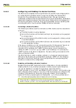

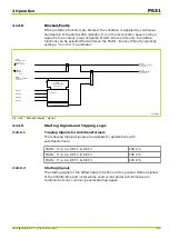
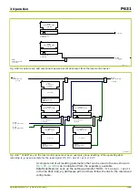

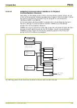
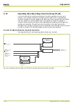
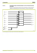

3.12.11
Resetting Actions
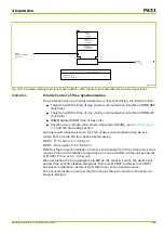
Stored data such as event logs, measured fault data etc, can be cleared in
several ways. The following types of resetting actions are possible:
●
Automatic resetting of the event signals provided by LED indicators (given
that the LED operating mode has been set accordingly) and of the display
of measured event data on the local control panel LCD whenever a new
event occurs. In this case only the displays on the local control panel LCD
are cleared but not the internal memories such as the fault memory.
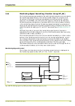
●
Resetting of LED indicators and measured event data displayed on the local
control panel LCD by pressing the “Clear” key located on the local
control panel. By selecting the required function at LOC: Fct. reset key
further memories may be assigned which will then also be cleared when
the “Clear” key is pressed.
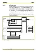
●
Selective resetting of a particular memory type (e.g. only the fault memory)
via setting parameters. (For this example: Navigate to menu point
FT_RC: Reset record. USER and set to
execute
, see also the exact step-
by-step description in
.)
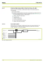
●
Selective resetting of a particular memory type (e.g. only the fault memory)
through appropriately configured binary signal inputs. (For this example:
Assign parameter FT_RC: Reset record. EXT to the relevant binary
signal input e.g. INP: Fct. assignm. U xxx .)
●
Group resetting by setting parameters, by navigating to menu point
MAIN: Group reset 1 USER (or MAIN: Group reset 2 USER) and
setting it to
execute
. For this the relevant memories (i.e. those to be reset)
must be assigned to parameter MAIN: Fct.assign. reset 1 (or
MAIN: Fct.assign. reset 2, resp.)
●
Group resetting through appropriately configured binary signal inputs.
(That is assign parameter MAIN: Group reset 1 EXT (or MAIN: Group
reset 2 EXT) to the relevant binary signal input, e.g. INP: Fct. assignm. U
xxx after memories to be reset have been assigned to parameter
MAIN: Fct.assign. reset 1 (or MAIN: Fct.assign. reset 2).
●
General resetting by setting parameters (menu point MAIN: General
reset USER). All memories, counters, events etc. are reset without any
special configuration options.
●
General resetting through appropriately configured binary signal inputs.
(MAIN: General reset EXT is assigned to the relevant binary signal
input.) All memories, counters, events etc. are reset without any special
configuration options.
Should several resetting actions have been configured for one particular memory
then they all have equal priority.
In the event of a cold restart, namely simultaneous failure of both internal
battery and substation auxiliary supply, all stored signals and values will be lost.
P631
3 Operation
3-84
P631/EN M/R-11-C // P631-310-650
Summary of Contents for P631
Page 2: ......
Page 4: ......
Page 7: ...Changes after going to press...
Page 8: ......
Page 16: ...P631 Table of Contents 8 P631 EN M R 11 C P631 310 650...
Page 56: ...P631 2 Technical Data 2 28 P631 EN M R 11 C P631 310 650...
Page 236: ...P631 3 Operation 3 180 P631 EN M R 11 C P631 310 650...
Page 246: ...P631 4 Design 4 10 P631 EN M R 11 C P631 310 650...
Page 266: ...P631 5 Installation and Connection 5 20 P631 EN M R 11 C P631 310 650...
Page 276: ...6 8 Configurable Function Keys P631 6 Local Control HMI 6 10 P631 EN M R 11 C P631 310 650...
Page 548: ...P631 10 Commissioning 10 10 P631 EN M R 11 C P631 310 650...
Page 568: ...P631 12 Maintenance 12 8 P631 EN M R 11 C P631 310 650...
Page 570: ...P631 13 Storage 13 2 P631 EN M R 11 C P631 310 650...
Page 572: ...P631 14 Accessories and Spare Parts 14 2 P631 EN M R 11 C P631 310 650...
Page 576: ...P631 15 Order Information 15 4 P631 EN M R 11 C P631 310 650...
Page 582: ...P631 A2 Internal Signals A2 4 P631 EN M R 11 C P631 310 650...
Page 608: ...P631 A4 Telecontrol Interfaces A4 18 P631 EN M R 11 C P631 310 650...
Page 637: ......