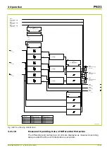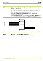
3.21
Differential Protection (Function Group DIFF)
The P631 is designed for the protection of transformers as well as for the
protection of motors and generators and of other two-winding arrangements.
For application of the device as transformer differential protection, amplitude
matching is required. This is achieved simply by setting of the reference power
‑
generally the nominal power of the transformer
‑
and of the primary nominal
voltages for all windings of the transformer.
Vector group matching is achieved by the straightforward input of the relevant
vector group identification number. For special applications, zero-sequence
current filtering may be deactivated. For conditions where it is possible to load
the transformer with a voltage in excess of the nominal voltage, the overfluxing
restraint prevents inappropriate tripping.
For application as differential protection device for motors or generators, the
harmonic restraint (inrush compensation) can be deactivated. The start-up of
directly switched asynchronous motors represents a problem in differential
protection due to transient transformer saturation caused by a displacement of
the start-up current for relatively high primary time constants. Even under these
unfavorable measurement conditions, the P631 exhibits an excellent stable
performance due to the application of a saturation discriminator.
All observations below are based on the assumption that the system current
transformers are connected to the P631 in standard configuration (see
). In particular, the application as transformer differential
protection device presupposes that winding ‘a’ corresponds to the high voltage
side of the transformer. For a non-standard connection, the appropriate settings
must be selected (see
).
3.21.1
Enabling or Disabling Differential Protection
Differential protection can be enabled or disabled from the local control panel.
Moreover, enabling can be done separately for each parameter subset.
3 Operation
P631
P631/EN M/R-11-C // P631-310-650
3-109
Summary of Contents for P631
Page 2: ......
Page 4: ......
Page 7: ...Changes after going to press...
Page 8: ......
Page 16: ...P631 Table of Contents 8 P631 EN M R 11 C P631 310 650...
Page 56: ...P631 2 Technical Data 2 28 P631 EN M R 11 C P631 310 650...
Page 236: ...P631 3 Operation 3 180 P631 EN M R 11 C P631 310 650...
Page 246: ...P631 4 Design 4 10 P631 EN M R 11 C P631 310 650...
Page 266: ...P631 5 Installation and Connection 5 20 P631 EN M R 11 C P631 310 650...
Page 276: ...6 8 Configurable Function Keys P631 6 Local Control HMI 6 10 P631 EN M R 11 C P631 310 650...
Page 548: ...P631 10 Commissioning 10 10 P631 EN M R 11 C P631 310 650...
Page 568: ...P631 12 Maintenance 12 8 P631 EN M R 11 C P631 310 650...
Page 570: ...P631 13 Storage 13 2 P631 EN M R 11 C P631 310 650...
Page 572: ...P631 14 Accessories and Spare Parts 14 2 P631 EN M R 11 C P631 310 650...
Page 576: ...P631 15 Order Information 15 4 P631 EN M R 11 C P631 310 650...
Page 582: ...P631 A2 Internal Signals A2 4 P631 EN M R 11 C P631 310 650...
Page 608: ...P631 A4 Telecontrol Interfaces A4 18 P631 EN M R 11 C P631 310 650...
Page 637: ......

