


K
d
=
K
max
≈
1 +
X
p
R
p
= 1 +
ω
·
T
p
However, this is not necessary. Instead, it is sufficient to consider an empirically
determined dimensioning factor K
d
=K
emp
such that the appropriate operation of
the protection function is ensured under the given conditions. This factor
depends on application and relay type, as outlined in the following.
2.13.3
Transformer Differential Protection
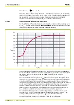
For Transformer Differential Protection Devices the empirical dimensioning factor
K
d
= K
emp
for the CTs considering external faults (assuming maximum through-
flowing currents) can be taken from the following diagram:
0
1.0
2.0
3.0
4.0
4.5
5.0
0
10
20
30
40
50
60
70
80
K
emp
X
p
/
p
R
0.5
1.5
2.5
3.5
This CT dimensioning assures through fault stability of the differential element.
Due to the inbuilt saturation discriminator the CT requirement is independent of
the current sensitivity given by the set basic threshold of the tripping
characteristic.
The empirical dimensioning factor K
emp
(shown in the diagram above) has been
determined by investigations using 3-shot auto-reclosing sequences with 450 ms
of fault current feed (starting at worst case point on wave) for each shot and
300 ms dead time between shots. In most practical cases faults would be cleared
in 100 to 200 ms for external protection operation and the dead time between
auto-reclose shots would be longer than 300 ms. This would reduce the flux
build-up in the core. Therefore the above shown empirical dimensioning factor
K
emp
can be considered as being based on a conservative approach.
For internal fault steady-state saturation is permissible with maximum fault
currents up to 4 times the steady-state accuracy limit current of the CT. This
corresponds to a dimensioning factor of K
d
= 0.25 for internal faults.
It is recommended to use CTs of accuracy class 5P (or equivalent).
2 Technical Data
P631
P631/EN M/R-11-C // P631-310-650
2-27
Summary of Contents for P631
Page 2: ......
Page 4: ......
Page 7: ...Changes after going to press...
Page 8: ......
Page 16: ...P631 Table of Contents 8 P631 EN M R 11 C P631 310 650...
Page 56: ...P631 2 Technical Data 2 28 P631 EN M R 11 C P631 310 650...
Page 236: ...P631 3 Operation 3 180 P631 EN M R 11 C P631 310 650...
Page 246: ...P631 4 Design 4 10 P631 EN M R 11 C P631 310 650...
Page 266: ...P631 5 Installation and Connection 5 20 P631 EN M R 11 C P631 310 650...
Page 276: ...6 8 Configurable Function Keys P631 6 Local Control HMI 6 10 P631 EN M R 11 C P631 310 650...
Page 548: ...P631 10 Commissioning 10 10 P631 EN M R 11 C P631 310 650...
Page 568: ...P631 12 Maintenance 12 8 P631 EN M R 11 C P631 310 650...
Page 570: ...P631 13 Storage 13 2 P631 EN M R 11 C P631 310 650...
Page 572: ...P631 14 Accessories and Spare Parts 14 2 P631 EN M R 11 C P631 310 650...
Page 576: ...P631 15 Order Information 15 4 P631 EN M R 11 C P631 310 650...
Page 582: ...P631 A2 Internal Signals A2 4 P631 EN M R 11 C P631 310 650...
Page 608: ...P631 A4 Telecontrol Interfaces A4 18 P631 EN M R 11 C P631 310 650...
Page 637: ......