


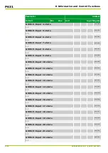


Parameter
Address
Default
Min
Max
Unit
Logic Diagram
Main function
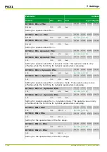
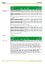
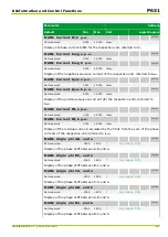
MAIN: Date
003 090
01.01.97
01.01.97 07.11.98 dd.mm.yy
[spacer]
Date display. The date can also be set here. The centuries are not displayed.
The supported dates range from January 1st, 1997, until November 7th, 2098.
[spacer]
MAIN: Time of day
003 091
00:00:00
00:00:00 24:00:00 hh:mm:ss
[spacer]
Display of the time of day. The time can also be set here.
[spacer]
MAIN: Time switching
003 095
0: Standard time
[spacer]
Setting for standard time or daylight saving time.
This setting is necessary in order to avoid misinterpretation of the times
assigned to signals and event data that can be read out through the PC or
communication interfaces.
[spacer]
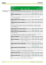
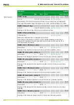
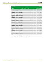
MAIN: Curr. IP,max,a prim.
005 101
Not measured
0
25000
A
[spacer]
Display of the maximum phase current as a primary quantity, end a.
[spacer]
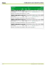
MAIN: IP,max prim.,delay a
005 162
Not measured
0
25000
A
[spacer]
Display of the delayed maximum current of end a as a primary quantity.
[spacer]
MAIN: IP,max prim.stored a
005 161
Not measured
0
25000
A
[spacer]
Display of the delayed stored maximum phase current of end a as a primary
quantity.
[spacer]
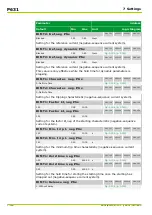
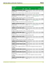
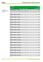
MAIN: Curr. IP,max,b prim.
005 102
Not measured
0
25000
A
[spacer]
Display of the maximum phase current as a primary quantity, end b.
[spacer]
MAIN: IP,max prim.,delay b
006 162
Not measured
0
25000
A
[spacer]
Display of the delayed maximum current of end b as a primary quantity.
[spacer]
MAIN: IP,max prim.stored b
006 161
Not measured
0
25000
A
[spacer]
Display of the delayed stored maximum phase current of end b as a primary
quantity.
[spacer]
MAIN: Curr. IP,min,a prim.
005 104
Not measured
0
25000
A
[spacer]
Display of the minimum phase current of end a as a primary quantity.
P631
8 Information and Control Functions
8-4
P631/EN M/R-11-C // P631-310-650
Summary of Contents for P631
Page 2: ......
Page 4: ......
Page 7: ...Changes after going to press...
Page 8: ......
Page 16: ...P631 Table of Contents 8 P631 EN M R 11 C P631 310 650...
Page 56: ...P631 2 Technical Data 2 28 P631 EN M R 11 C P631 310 650...
Page 236: ...P631 3 Operation 3 180 P631 EN M R 11 C P631 310 650...
Page 246: ...P631 4 Design 4 10 P631 EN M R 11 C P631 310 650...
Page 266: ...P631 5 Installation and Connection 5 20 P631 EN M R 11 C P631 310 650...
Page 276: ...6 8 Configurable Function Keys P631 6 Local Control HMI 6 10 P631 EN M R 11 C P631 310 650...
Page 548: ...P631 10 Commissioning 10 10 P631 EN M R 11 C P631 310 650...
Page 568: ...P631 12 Maintenance 12 8 P631 EN M R 11 C P631 310 650...
Page 570: ...P631 13 Storage 13 2 P631 EN M R 11 C P631 310 650...
Page 572: ...P631 14 Accessories and Spare Parts 14 2 P631 EN M R 11 C P631 310 650...
Page 576: ...P631 15 Order Information 15 4 P631 EN M R 11 C P631 310 650...
Page 582: ...P631 A2 Internal Signals A2 4 P631 EN M R 11 C P631 310 650...
Page 608: ...P631 A4 Telecontrol Interfaces A4 18 P631 EN M R 11 C P631 310 650...
Page 637: ......