


3.2
Operator-Machine Communication
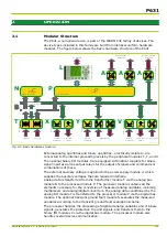
The following interfaces are available for the exchange of information between
the user and the P631:
●
Integrated user interface (LOC: local control panel)
●
PC interface
●
Communication interface
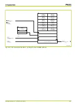
All settings and signals as well as all measurements and control functions are
arranged within the branches of the menu tree following a scheme that is
uniform throughout the device family. The main branches are:
“Parameters” Branch
All settings are contained in this branch. This branch carries all settings,
including the identification data of the P631, the configuration parameters for
adapting the P631 interfaces to the system, and the function parameters for
adapting the device functions to the process. All values in this group are stored
in non-volatile memory, which means that the values will be preserved even if
the power supply fails.
“Operation” Branch
This branch includes all information relevant for operation such as measured
operating data and binary signal states. This information is updated periodically
and consequently is not stored. In addition, various controls are grouped here,
for example those for resetting counters, memories and displays.
“Events” Branch
The third branch is reserved for the recording of events. All information in this
group is therefore stored. In particular, the start/end signals during a fault, the
measured fault data, and the sampled fault waveforms are stored here and can
be read out when required.
Display of Settings and Signals
Settings and signals are displayed either in plain text or as addresses, in
accordance with the user’s choice. All settings and signals of the P631 are
documented in a separate collection of documents, the so-called
“DataModelExplorer”. The “Addresses” document (being part of the
“DataModelExplorer”) is complete in the sense that it contains all settings,
signals and measured variables that are relevant for the user of the P631.
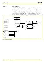
The configuration of the local control panel also permits the installation of
Measured Value “Panels” on the LCD display. Different Panels are automatically
displayed for specific system operating conditions. Priority increases from normal
operation to operation under overload conditions and finally to operation
following a short circuit in the system. Thus the P631 provides the measured
data relevant for the prevailing conditions.
3 Operation
P631
P631/EN M/R-11-C // P631-310-650
3-3
Summary of Contents for P631
Page 2: ......
Page 4: ......
Page 7: ...Changes after going to press...
Page 8: ......
Page 16: ...P631 Table of Contents 8 P631 EN M R 11 C P631 310 650...
Page 56: ...P631 2 Technical Data 2 28 P631 EN M R 11 C P631 310 650...
Page 236: ...P631 3 Operation 3 180 P631 EN M R 11 C P631 310 650...
Page 246: ...P631 4 Design 4 10 P631 EN M R 11 C P631 310 650...
Page 266: ...P631 5 Installation and Connection 5 20 P631 EN M R 11 C P631 310 650...
Page 276: ...6 8 Configurable Function Keys P631 6 Local Control HMI 6 10 P631 EN M R 11 C P631 310 650...
Page 548: ...P631 10 Commissioning 10 10 P631 EN M R 11 C P631 310 650...
Page 568: ...P631 12 Maintenance 12 8 P631 EN M R 11 C P631 310 650...
Page 570: ...P631 13 Storage 13 2 P631 EN M R 11 C P631 310 650...
Page 572: ...P631 14 Accessories and Spare Parts 14 2 P631 EN M R 11 C P631 310 650...
Page 576: ...P631 15 Order Information 15 4 P631 EN M R 11 C P631 310 650...
Page 582: ...P631 A2 Internal Signals A2 4 P631 EN M R 11 C P631 310 650...
Page 608: ...P631 A4 Telecontrol Interfaces A4 18 P631 EN M R 11 C P631 310 650...
Page 637: ......