


Parameter
Address
Default
Min
Max
Unit
Logic Diagram
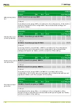
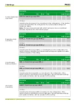
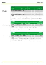
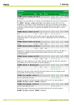
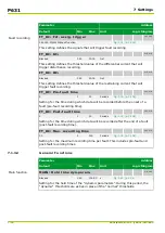
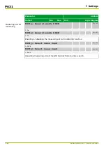
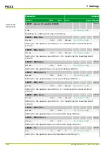
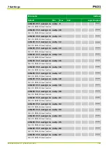
Fault recording
FT_RC: Fct. assig. trigger
003 085
060 000: MAIN: Without function
[spacer]
This setting defines the signals that will trigger fault recording.
[spacer]
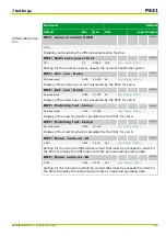
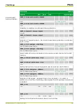
FT_RC: Id>
016 018
Blocked
0.01
30.00
Iref
[spacer]
This setting defines the threshold value of the differential current that will
trigger disturbance recording.
[spacer]
FT_RC: IR>
016 019
Blocked
0.01
30.00
Iref
[spacer]
This setting defines the threshold value of the restraining current that will
trigger fault recording.
[spacer]
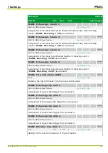
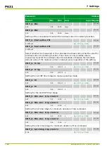
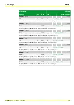
FT_RC: Pre-fault time
003 078
5
1
50
Periods
[spacer]
Setting for the time during which data will be recorded before the onset of a
fault (pre-fault recording time).
[spacer]
FT_RC: Post-fault time
003 079
2
1
50
Periods
[spacer]
Setting for the time during which data will be recorded after the end of a fault
(post-fault recording time).
[spacer]
FT_RC: Max. recording time
003 075
50
5
300
Periods
[spacer]
Setting for the maximum recording time per fault. This includes pre-fault and
post-fault recording times.
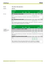
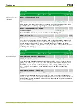
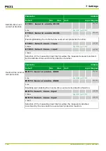
7.1.3.2
General Functions
Parameter
Address
Default
Min
Max
Unit
Logic Diagram
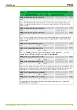
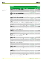
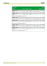
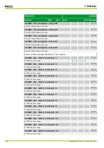
Main function
MAIN: Hold time dyn.param.
018 009
Blocked
0.00
100.00
s
[spacer]
Setting for the hold time of the “dynamic parameters”. During this period, the
“dynamic” thresholds are active in place of the “normal” thresholds.
P631
7 Settings
7-78
P631/EN M/R-11-C // P631-310-650
Summary of Contents for P631
Page 2: ......
Page 4: ......
Page 7: ...Changes after going to press...
Page 8: ......
Page 16: ...P631 Table of Contents 8 P631 EN M R 11 C P631 310 650...
Page 56: ...P631 2 Technical Data 2 28 P631 EN M R 11 C P631 310 650...
Page 236: ...P631 3 Operation 3 180 P631 EN M R 11 C P631 310 650...
Page 246: ...P631 4 Design 4 10 P631 EN M R 11 C P631 310 650...
Page 266: ...P631 5 Installation and Connection 5 20 P631 EN M R 11 C P631 310 650...
Page 276: ...6 8 Configurable Function Keys P631 6 Local Control HMI 6 10 P631 EN M R 11 C P631 310 650...
Page 548: ...P631 10 Commissioning 10 10 P631 EN M R 11 C P631 310 650...
Page 568: ...P631 12 Maintenance 12 8 P631 EN M R 11 C P631 310 650...
Page 570: ...P631 13 Storage 13 2 P631 EN M R 11 C P631 310 650...
Page 572: ...P631 14 Accessories and Spare Parts 14 2 P631 EN M R 11 C P631 310 650...
Page 576: ...P631 15 Order Information 15 4 P631 EN M R 11 C P631 310 650...
Page 582: ...P631 A2 Internal Signals A2 4 P631 EN M R 11 C P631 310 650...
Page 608: ...P631 A4 Telecontrol Interfaces A4 18 P631 EN M R 11 C P631 310 650...
Page 637: ......