


Parameter
Address
Default
Min
Max
Unit
Logic Diagram
[spacer]
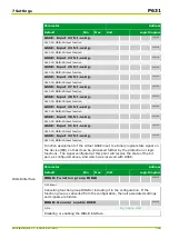
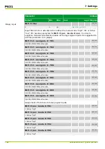
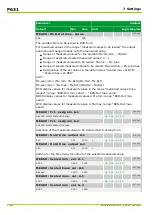
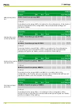
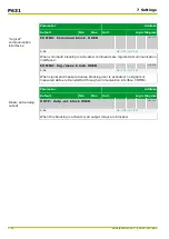
MEASO: BCD-Out max. value
037 143
399
0
399
[spacer]
The variable Mx is to be issued in BCD form.
For measured values in the range “measured values to be issued” the output
value should change linearly with the measured value.
●
Range of measured values for the variable Mx: Mx,RL1 ... Mx,RL2
●
Range of associated scaled measured values: 0 ... 1
●
Range of measured values to be issued: Mx,min ... Mx,max
●
Range of scaled measured values to be issued: Mx,scal,min ... Mx,scal,max
●
Designation of the set values in the data model: “Scaled min. val. BCD” ...
“Scaled max. val. BCD”
with:
Mx,scal,min = (Mx,min - Mx,RL1)/(Mx,RL2 - Mx,RL1)
Mx,scal,max = (Mx,max - Mx,RL1)/(Mx,RL2 - Mx,RL1)
BCD display values for measured values in the range “measured values to be
issued”; range: “BCD-Out min. value” ... “BCD-Out max. value”
BBCD display values for measured values
≤
Mx,min; range: “BCD-Out min.
value”
BCD display values for measured values
≥
Mx,max; range: “BCD-Out max.
value”
[spacer]
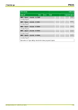
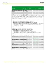
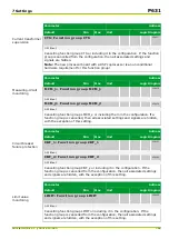
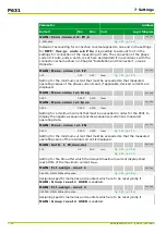
MEASO: Fct. assignm. A-1
053 000
060 000: MAIN: Without function
[spacer]
MEASO: Fct. assignm. A-2
053 001
060 000: MAIN: Without function
[spacer]
Selection of the measured value to be transmitted in analog form.
[spacer]
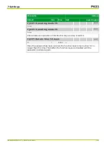
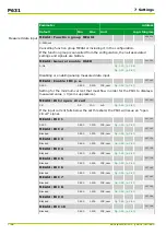
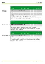
MEASO: Hold time output A-1
010 114
0.10
0.10
10.00
s
[spacer]
MEASO: Hold time output A-2
010 115
0.10
0.10
10.00
s
[spacer]
Setting for the time delay for output of the selected measured value.
[spacer]
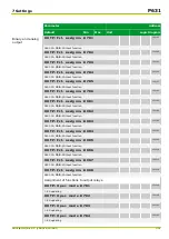
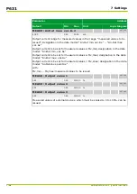
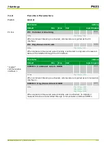
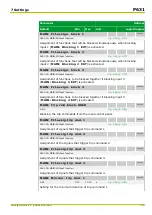
MEASO: Scaled min. val. A-1
037 104
0.000
0.000
1.000
[spacer]
MEASO: Scaled knee val. A-1
037 105
Blocked
0.000
1.000
[spacer]
MEASO: Scaled max. val. A-1
037 106
1.000
0.000
1.000
[spacer]
MEASO: Scaled min. val. A-2
037 110
0.000
0.000
1.000
P631
7 Settings
7-60
P631/EN M/R-11-C // P631-310-650
Summary of Contents for P631
Page 2: ......
Page 4: ......
Page 7: ...Changes after going to press...
Page 8: ......
Page 16: ...P631 Table of Contents 8 P631 EN M R 11 C P631 310 650...
Page 56: ...P631 2 Technical Data 2 28 P631 EN M R 11 C P631 310 650...
Page 236: ...P631 3 Operation 3 180 P631 EN M R 11 C P631 310 650...
Page 246: ...P631 4 Design 4 10 P631 EN M R 11 C P631 310 650...
Page 266: ...P631 5 Installation and Connection 5 20 P631 EN M R 11 C P631 310 650...
Page 276: ...6 8 Configurable Function Keys P631 6 Local Control HMI 6 10 P631 EN M R 11 C P631 310 650...
Page 548: ...P631 10 Commissioning 10 10 P631 EN M R 11 C P631 310 650...
Page 568: ...P631 12 Maintenance 12 8 P631 EN M R 11 C P631 310 650...
Page 570: ...P631 13 Storage 13 2 P631 EN M R 11 C P631 310 650...
Page 572: ...P631 14 Accessories and Spare Parts 14 2 P631 EN M R 11 C P631 310 650...
Page 576: ...P631 15 Order Information 15 4 P631 EN M R 11 C P631 310 650...
Page 582: ...P631 A2 Internal Signals A2 4 P631 EN M R 11 C P631 310 650...
Page 608: ...P631 A4 Telecontrol Interfaces A4 18 P631 EN M R 11 C P631 310 650...
Page 637: ......