3.12.9.7
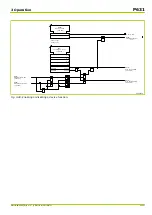
Blocking of the Trip Commands
The trip commands can be blocked via parameters or an appropriately
configured binary signal input. This blocking is then effective for all four trip
commands. The trip signals are not affected by this blocking. If the trip
commands are blocked, it is indicated by the continuously illuminated amber LED
indicator H 2 on the local control panel and by a signal from an output relay
configured to “Blocked/Faulty”. (To identify H 2, see the dimensional drawings in
the
.)
3.12.9.8
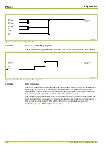
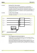
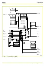
Counter of Trip Commands
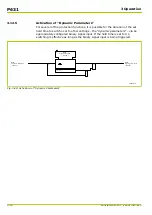
The number of trip commands is counted. The counters can be reset either
individually or as a group.
Q6Z0145A
MAIN:
No. gen.trip cmds. 1
[ 004 006 ]
MAIN:
No. gen.trip cmds. 2
[ 009 050 ]
MAIN:
No. gen.trip cmds. 3
[ 009 056 ]
MAIN:
No. gen.trip cmds. 4
[ 009 057 ]
MAIN:
Gen. trip command 1
[ 036 071 ]
MAIN:
General reset USER
[ 003 002 ]
1: execute
MAIN:
Gen. trip command 2
[ 036 022 ]
MAIN:
Gen. trip command 3
[ 036 113 ]
MAIN:
Gen. trip command 4
[ 036 114 ]
MAIN:
Reset c. cl/tr.cUSER
[ 003 007 ]
0
0: don't execute
1
1: execute
R
R
R
R
Fig. 3-56: Counter of trip commands
3.12.10
Time Tagging and Clock Synchronization
The data stored in the operating data memory, the monitoring signal memory
and the event memories are date- and time-tagged. For correct tagging, the date
and time need to be set in the P631.
The time of different devices may be synchronized by a pulse given to an
appropriately configured binary signal input. The P631 evaluates the rising edge.
This will set the clock to the nearest full minute, rounding either up or down. If
several start/end signals occur (bouncing of a relay contact), only the last edge is
evaluated.
P631
3 Operation
3-82
P631/EN M/R-11-C // P631-310-650
Summary of Contents for P631
Page 2: ......
Page 4: ......
Page 7: ...Changes after going to press...
Page 8: ......
Page 16: ...P631 Table of Contents 8 P631 EN M R 11 C P631 310 650...
Page 56: ...P631 2 Technical Data 2 28 P631 EN M R 11 C P631 310 650...
Page 236: ...P631 3 Operation 3 180 P631 EN M R 11 C P631 310 650...
Page 246: ...P631 4 Design 4 10 P631 EN M R 11 C P631 310 650...
Page 266: ...P631 5 Installation and Connection 5 20 P631 EN M R 11 C P631 310 650...
Page 276: ...6 8 Configurable Function Keys P631 6 Local Control HMI 6 10 P631 EN M R 11 C P631 310 650...
Page 548: ...P631 10 Commissioning 10 10 P631 EN M R 11 C P631 310 650...
Page 568: ...P631 12 Maintenance 12 8 P631 EN M R 11 C P631 310 650...
Page 570: ...P631 13 Storage 13 2 P631 EN M R 11 C P631 310 650...
Page 572: ...P631 14 Accessories and Spare Parts 14 2 P631 EN M R 11 C P631 310 650...
Page 576: ...P631 15 Order Information 15 4 P631 EN M R 11 C P631 310 650...
Page 582: ...P631 A2 Internal Signals A2 4 P631 EN M R 11 C P631 310 650...
Page 608: ...P631 A4 Telecontrol Interfaces A4 18 P631 EN M R 11 C P631 310 650...
Page 637: ......

