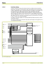

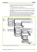

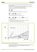
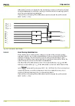

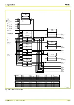


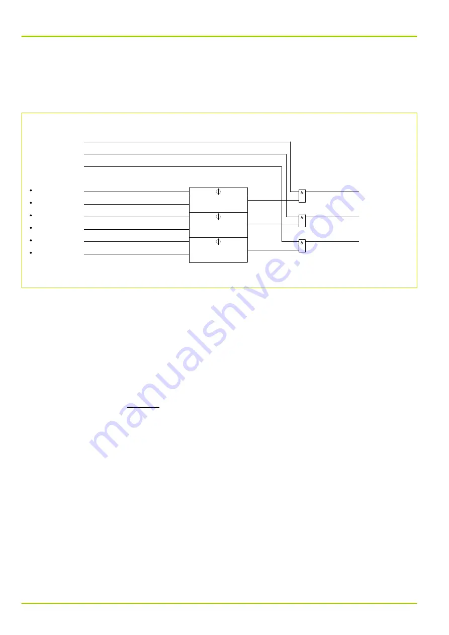
differential current as compared to the restraining current, and thus the desired
through-stabilization is achieved. Locking is restricted to the measuring system
where an external fault was detected.
There will be no blocking if the differential current exceeds the set threshold
DIFF: Idiff>> PSx.
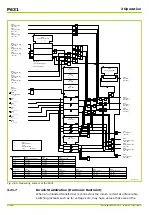
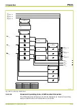
Q6Z0111A
DIFF:
Id,1
303 303
DIFF:
Id,2
303 304
DIFF:
Id,3
303 307
DIFF:
Meas.system 1 trigg.
[ 041 124 ]
DIFF:
Meas.system 2 trigg.
[ 041 125 ]
DIFF:
Meas.system 3 trigg.
[ 041 126 ]
DIFF:
IR,3
303 308
DIFF:
IR,2
303 306
DIFF:
IR,1
303 305
DIFF:
Sat.discr. 1 trigg.
[ 041 115 ]
DIFF:
Sat.discr. 2 trigg.
[ 041 116 ]
DIFF:
Sat.discr. 3 trigg.
[ 041 117 ]
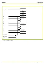
Fig. 3-87: Saturation discriminator
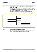
3.21.9
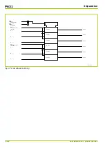
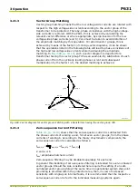
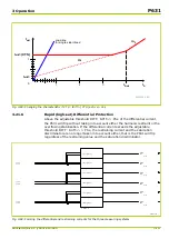
Overfluxing Stabilization
If the transformer is loaded with a voltage in excess of the nominal voltage,
saturation effects occur. Without stabilization, these could lead to differential
protection tripping. The fact that the current of the protected object under
saturation conditions has a high proportion of harmonics having five times the
system frequency serves as the basis of stabilization.
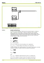
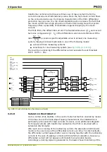
The P631 filters the differential current. The fundamental wave
I
(
f
0
)
and fifth
harmonic components
I
(
5
⋅
f
0
)
of the differential current are determined. If the
ratio
I
(
5
⋅
f
0
)
I
(
f
0
)
exceeds the set value DIFF: Ov. I(5f0)/I(f0) PSx in at least one
measuring system, and if the differential current is smaller than 4·I
ref
, then
tripping is blocked selectively for one measuring system.
There will be no blocking if the differential current exceeds the set threshold
DIFF: Idiff>> PSx.
P631
3 Operation
3-120
P631/EN M/R-11-C // P631-310-650
Summary of Contents for P631
Page 2: ......
Page 4: ......
Page 7: ...Changes after going to press...
Page 8: ......
Page 16: ...P631 Table of Contents 8 P631 EN M R 11 C P631 310 650...
Page 56: ...P631 2 Technical Data 2 28 P631 EN M R 11 C P631 310 650...
Page 236: ...P631 3 Operation 3 180 P631 EN M R 11 C P631 310 650...
Page 246: ...P631 4 Design 4 10 P631 EN M R 11 C P631 310 650...
Page 266: ...P631 5 Installation and Connection 5 20 P631 EN M R 11 C P631 310 650...
Page 276: ...6 8 Configurable Function Keys P631 6 Local Control HMI 6 10 P631 EN M R 11 C P631 310 650...
Page 548: ...P631 10 Commissioning 10 10 P631 EN M R 11 C P631 310 650...
Page 568: ...P631 12 Maintenance 12 8 P631 EN M R 11 C P631 310 650...
Page 570: ...P631 13 Storage 13 2 P631 EN M R 11 C P631 310 650...
Page 572: ...P631 14 Accessories and Spare Parts 14 2 P631 EN M R 11 C P631 310 650...
Page 576: ...P631 15 Order Information 15 4 P631 EN M R 11 C P631 310 650...
Page 582: ...P631 A2 Internal Signals A2 4 P631 EN M R 11 C P631 310 650...
Page 608: ...P631 A4 Telecontrol Interfaces A4 18 P631 EN M R 11 C P631 310 650...
Page 637: ......