


Parameter
Address
Default
Min
Max
Unit
Logic Diagram
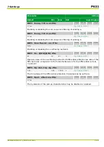
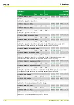
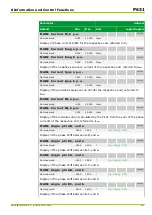
Inverse-time overcur
‐
rent protection
IDMT1: Enable PSx
081 050
082 050
083 050
084 050
0: No
[spacer]
IDMT2: Enable PSx
081 170
082 170
083 170
084 170
0: No
[spacer]
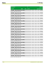
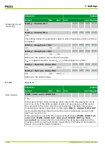
This setting specifies the parameter subset to be enabled for inverse-time
overcurrent protection.
[spacer]
IDMT1: Block tim.st. IN PSx
081 068
082 068
083 068
084 068
0: Without
[spacer]
IDMT2: Block tim.st. IN PSx
081 188
082 188
083 188
084 188
0: Without
[spacer]
This setting defines whether a blocking of the residual and negative-sequence
current stages should take place for single-pole startings or multi-pole phase
current startings.
[spacer]
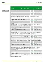
IDMT1: Gen.starting modePSx
081 059
082 059
083 059
084 059
1: With start. IN/Ineg
[spacer]
IDMT2: Gen.starting modePSx
081 179
082 179
083 179
084 179
1: With start. IN/Ineg
[spacer]
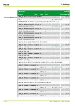
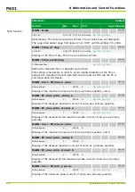
This setting defines whether starting of the residual current stages will result in
the formation of the general starting signal of IDMT protection.
[spacer]
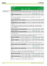
IDMT1: tGS PSx
081 058
082 058
083 058
084 058
0.00
0.00
100.00
s
[spacer]
IDMT2: tGS PSx
081 178
082 178
083 178
084 178
0.00
0.00
100.00
s
[spacer]
Setting for the operate delay of the general starting signal of IDMT protection.
[spacer]
IDMT1: Rush restr.enabl PSx
081 060
082 060
083 060
084 060
0: No
Fig. 3-103, (p. 3-138)
Fig. 3-104, (p. 3-140)
[spacer]
IDMT2: Rush restr.enabl PSx
081 180
082 180
083 180
084 180
0: No
[spacer]
Setting as to whether the inrush restraint of differential protection shall be able
to block the inverse-time overcurrent protection function.
[spacer]
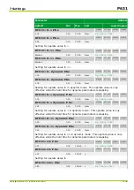
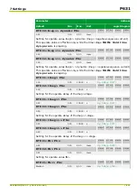
IDMT1: Iref,P PSx
081 051
082 051
083 051
084 051
1.00
0.10
4.00
Inom
[spacer]
IDMT2: Iref,P PSx
081 171
082 171
083 171
084 171
1.00
0.10
4.00
Inom
[spacer]
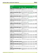
Setting for the reference current (phase current system).
P631
7 Settings
7-114
P631/EN M/R-11-C // P631-310-650
Summary of Contents for P631
Page 2: ......
Page 4: ......
Page 7: ...Changes after going to press...
Page 8: ......
Page 16: ...P631 Table of Contents 8 P631 EN M R 11 C P631 310 650...
Page 56: ...P631 2 Technical Data 2 28 P631 EN M R 11 C P631 310 650...
Page 236: ...P631 3 Operation 3 180 P631 EN M R 11 C P631 310 650...
Page 246: ...P631 4 Design 4 10 P631 EN M R 11 C P631 310 650...
Page 266: ...P631 5 Installation and Connection 5 20 P631 EN M R 11 C P631 310 650...
Page 276: ...6 8 Configurable Function Keys P631 6 Local Control HMI 6 10 P631 EN M R 11 C P631 310 650...
Page 548: ...P631 10 Commissioning 10 10 P631 EN M R 11 C P631 310 650...
Page 568: ...P631 12 Maintenance 12 8 P631 EN M R 11 C P631 310 650...
Page 570: ...P631 13 Storage 13 2 P631 EN M R 11 C P631 310 650...
Page 572: ...P631 14 Accessories and Spare Parts 14 2 P631 EN M R 11 C P631 310 650...
Page 576: ...P631 15 Order Information 15 4 P631 EN M R 11 C P631 310 650...
Page 582: ...P631 A2 Internal Signals A2 4 P631 EN M R 11 C P631 310 650...
Page 608: ...P631 A4 Telecontrol Interfaces A4 18 P631 EN M R 11 C P631 310 650...
Page 637: ......