
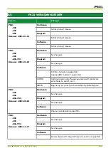


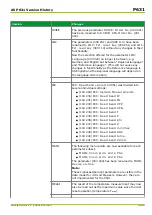
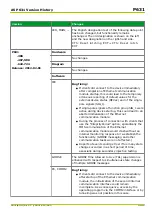
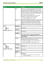


Version
Changes
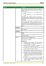
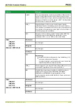
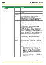
IEC
The data model of the measured operating values for
differential current and restraining current in the DIFF
function is now implemented according to the data
attributes for the standard WYE, ACT and ACD classes.
Note:
With this implementation, the “phase” measured
values from the DIFF protection function correspond to
the measured values of the three measuring systems:
●
“phSA” = Measuring system 1
●
“phSB” = Measuring system 2
●
“phSC” = Measuring system 3
ICD and PICS-MICS-ADL files have been upgraded
accordingly.
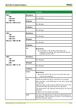
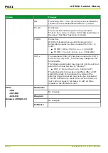
P631
‑
307
‑
405/406
‑
611
Release: 2007-11-05
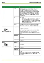
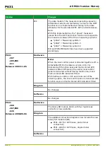
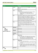
Hardware
Note:
When the local control panel is ordered together with a
detachable HMI for hardware version -306, it is
delivered with function keys and multi-colored LED
indicators fitted. Otherwise the earlier local control
panel is delivered without having function keys and
multi-colored LED indicators fitted.
With hardware version -307 and irrelevant of the
ordering option, the local control panel is delivered with
function keys and multi-colored LED indicators fitted.
Diagram
No changes.
Software
No changes.
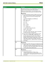
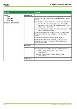
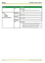
P631
‑
308
‑
407/408
‑
620
Release: 2008-06-06
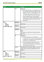
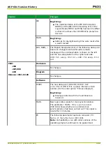
Hardware
The binary I/O module X(4H) with four high-break
contacts is now available.
Diagram
The updated connection diagrams now include the new
binary I/O module X(4H).
●
P631 -407 (for 40TE case, pin-terminal
connection)
●
P631 -408 (for 40TE case, ring-terminal
connection)
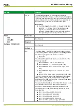
Software
P631
A5 P631 Version History
A5-14
P631/EN M/R-11-C // P631-310-650
Summary of Contents for P631
Page 2: ......
Page 4: ......
Page 7: ...Changes after going to press...
Page 8: ......
Page 16: ...P631 Table of Contents 8 P631 EN M R 11 C P631 310 650...
Page 56: ...P631 2 Technical Data 2 28 P631 EN M R 11 C P631 310 650...
Page 236: ...P631 3 Operation 3 180 P631 EN M R 11 C P631 310 650...
Page 246: ...P631 4 Design 4 10 P631 EN M R 11 C P631 310 650...
Page 266: ...P631 5 Installation and Connection 5 20 P631 EN M R 11 C P631 310 650...
Page 276: ...6 8 Configurable Function Keys P631 6 Local Control HMI 6 10 P631 EN M R 11 C P631 310 650...
Page 548: ...P631 10 Commissioning 10 10 P631 EN M R 11 C P631 310 650...
Page 568: ...P631 12 Maintenance 12 8 P631 EN M R 11 C P631 310 650...
Page 570: ...P631 13 Storage 13 2 P631 EN M R 11 C P631 310 650...
Page 572: ...P631 14 Accessories and Spare Parts 14 2 P631 EN M R 11 C P631 310 650...
Page 576: ...P631 15 Order Information 15 4 P631 EN M R 11 C P631 310 650...
Page 582: ...P631 A2 Internal Signals A2 4 P631 EN M R 11 C P631 310 650...
Page 608: ...P631 A4 Telecontrol Interfaces A4 18 P631 EN M R 11 C P631 310 650...
Page 637: ......