
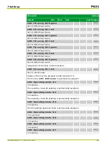


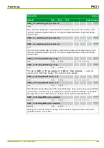
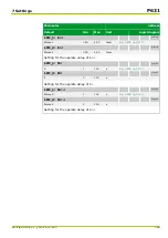

Parameter
Address
Default
Min
Max
Unit
Logic Diagram
[spacer]
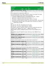
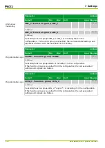
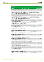
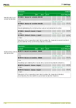
MAIN: Conn.meas.circ. IP,b
010 150
1: Standard
[spacer]
Instead of accounting for connection reversal applied to one end in the settings
for DIFF: Vec.gr. ends a-b PSx, it is possible to account for it in the
settings for connection of the measuring circuits. The connection of the phase
current circuits, ends a and b, is set here as
Standard
if in accordance with the
connection scheme shown in Chapter “Installation and Connection”, else as
Opposite
.
[spacer]
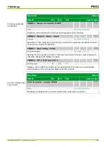
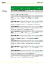
MAIN: Meas. value rel. IP
011 030
0.00
0.00
0.20
Inom
[spacer]
Setting for the minimum current that must be exceeded so that measured
operating values of the phase currents and, if applicable, derived currents are
displayed.
[spacer]
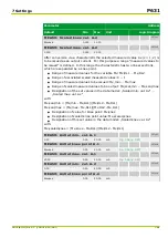
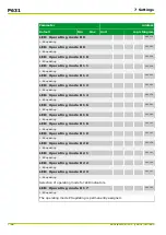
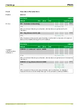
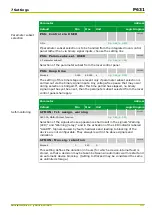
MAIN: Meas.value rel. Ineg
011 048
0.000
0.000
0.200
Inom
[spacer]
MAIN: Meas.value rel. Ipos
011 058
0.000
0.000
0.200
Inom
[spacer]
Setting for a minimum current that must be exceeded in order for the P631 to
display the negative-sequence (positive-sequence) current as measured
operating data.
[spacer]
MAIN: Meas. value rel. IN
011 031
0.000
0.000
0.200
Inom
[spacer]
Setting for the minimum current that must be exceeded so that the measured
operating value of the residual current is displayed.
[spacer]
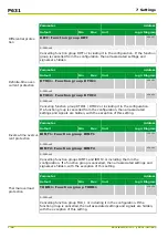
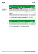
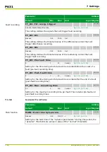
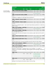
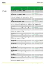
MAIN: Settl. t. IP,max,del
010 113
15.0
0.1
60.0
min
Fig. 3-43, (p. 3-69)
Fig. 3-44, (p. 3-70)
[spacer]
Setting for the time after which the delayed maximum current display shall
reach 95% of the maximum current I
P,max
.
[spacer]
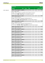
MAIN: Fct.assign. reset 1
005 248
060 000: MAIN: Without function
[spacer]
Assigning specific memories and counters which are to be reset jointly if
MAIN: Group reset 1 USER is enabled.
[spacer]
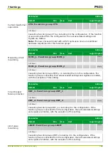
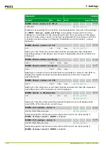
MAIN: Fct.assign. reset 2
005 249
060 000: MAIN: Without function
[spacer]
Assigning specific memories and counters which are to be reset jointly if
MAIN: Group reset 2 USER is enabled.
P631
7 Settings
7-74
P631/EN M/R-11-C // P631-310-650
Summary of Contents for P631
Page 2: ......
Page 4: ......
Page 7: ...Changes after going to press...
Page 8: ......
Page 16: ...P631 Table of Contents 8 P631 EN M R 11 C P631 310 650...
Page 56: ...P631 2 Technical Data 2 28 P631 EN M R 11 C P631 310 650...
Page 236: ...P631 3 Operation 3 180 P631 EN M R 11 C P631 310 650...
Page 246: ...P631 4 Design 4 10 P631 EN M R 11 C P631 310 650...
Page 266: ...P631 5 Installation and Connection 5 20 P631 EN M R 11 C P631 310 650...
Page 276: ...6 8 Configurable Function Keys P631 6 Local Control HMI 6 10 P631 EN M R 11 C P631 310 650...
Page 548: ...P631 10 Commissioning 10 10 P631 EN M R 11 C P631 310 650...
Page 568: ...P631 12 Maintenance 12 8 P631 EN M R 11 C P631 310 650...
Page 570: ...P631 13 Storage 13 2 P631 EN M R 11 C P631 310 650...
Page 572: ...P631 14 Accessories and Spare Parts 14 2 P631 EN M R 11 C P631 310 650...
Page 576: ...P631 15 Order Information 15 4 P631 EN M R 11 C P631 310 650...
Page 582: ...P631 A2 Internal Signals A2 4 P631 EN M R 11 C P631 310 650...
Page 608: ...P631 A4 Telecontrol Interfaces A4 18 P631 EN M R 11 C P631 310 650...
Page 637: ......