background image

SECTION 4 

OPERATOR MAINTENANCE 


63 


5.


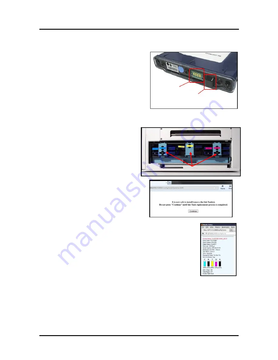
Lightly clean the QA Chip contacts 

[C] 

with a pencil eraser. 


6.


Clean the Ink Level Prism 

[D]

 and QA Chip 

contacts 

[C]

 with a clean, dry, lint-free cloth. 

NOTE: 

You can dampen the cloth with distilled 

water to wipe the Prism, but DO NOT get the 
QA Chip contacts wet. 


7.


Reinstall the Ink Tank(s) (

label up

) and securely 

latch the Ink Tank Latch(es). 

INSTALLATION TIP: 

Make sure the Ink 

Tanks seat properly. Insert the Tank into the 
appropriate Ink Station, then pull the Tank back 
about an inch and push forward firmly to insure 
that the Ink Nozzles penetrate the seals on the Ink Tanks.


8.


Close and lock all three Ink Tank Securing 
Latches.


IMPORTANT:

 Make sure both sides of 

the Latch are engaged at the bottom. 


9.


Click on the button labeled 

“Continue”, 

in the 

Confirm screen of the Toolbox. 


10.


Watch the Toolbox screen on your computer. You should see all the ink 
colors fill-in; if all the Ink Tanks are properly installed and recognized. 
 

Tip:

 If an Ink Tank color still does not fill-in. Press the “Refresh Ink Level” 

button. If the problem continues you may need to replace the Tank with a 
new/known good Tank.  
Even new Ink Tanks can have dirty/corroded QA Chip contacts. This is not 
always visible to the eye. 


If problem persists after replacing with a “new/known good” Tank; please 
call for service.


11.


Close the Ink Tank Door.


C


D


Summary of Contents for MACH X

Page 1: ...MACH X DIGITAL COLOR LABEL PRINTER OPERATOR s GUIDE Rev 4 14 15 Valid with R13 11 driver and 2015xxxx Firmware...

Page 2: ...th other equipment Make sure there is no strain on the power cord caused by jamming between equipment walls or furniture DO NOT remove covers Covers enclose hazardous parts that should only be accesse...

Page 3: ...NDER PACKAGING 15 CONTENTS OF WINDER PACKAGING 15 REMOVING THE CARDBOARD SHIPPING INSERT 16 INSTALL PRINTER WINDER SPACER PLATE 17 CONNECTING THE PRINTER 18 Plugging in the Printer 18 Powering the Pri...

Page 4: ...ervice Life yield 64 Ink Tank Disposal 64 PRINTHEAD 65 Cleaning the Printhead Cartridge 65 From the MC Series Driver 65 From the Toolbox 65 Manual Printhead Cleaning 66 REMOVING REPLACING THE PRINTHEA...

Page 5: ...Print Quality Issues including possible causes and solutions 91 THE INK TANK S 97 THE PRINTHEAD CARTRIDGE 98 THE PRINTER 100 Dots Printed on Media 100 Power Problems 100 Service Station Problems 101...

Page 6: ..._________________________________________________ ______________________________________________________ ______________________________________________________ ________________________________________...

Page 7: ...s to the printer here 7 Network Connection Ethernet The network cable plugs in here 8 Main Power Switch Receptacle and Fuse Plug in AC power cord here Switch turns main power on or off Fuse provides o...

Page 8: ...ON OFF button before powering off the Main Power Switch If this power down process is not followed loss of settings poor image quality and reduced printhead life may result IMPORTANT To provide prope...

Page 9: ...thead Latch extends and retracts the couplings from the Printhead 3 Printhead Cartridge Memjet Printhead produces an 8 5 wide full color print area 4 Clamshell Latches Lift both latches at the same ti...

Page 10: ...ray The purpose of this tray is to catch any waste ink produced by the system This tray is filled with absorbent material The tabs located at the left and right sides of the tray secure the tray to th...

Page 11: ...he Media 7 Label Tension Arm Position of weighted shaft controls stopping starting and rotation direction of Unwinder as tension is maintained or released by media web 8 24V 2 5A External Power Connec...

Page 12: ...using the Tension Control Selector 10 8 Media Guide Ring Slides to fit width of media 9 Winder Alignment Notch Aligns with the notch on the Spacer Plate mounted on the Printer Plate is then attached t...

Page 13: ...ting to print a job make sure the Printer Unwinder and Winder are set up correctly for that particular job PRINTING MODE UNWINDER WINDER CUTTER Roll to Roll Connected to Printer Powered ON and Connect...

Page 14: ...ase the button Press to Pause the Job Printer will finish printing the labels media in progress then stop and hold Press to Resume Printing Press to continue printing the job after a Pause or feed err...

Page 15: ...power switch LOAD FEED PAUSE RESUME Press to Load Labels Media Press to initially load labels media into the Printer Press to Pause the Job Printer will finish printing the labels media in progress c...

Page 16: ...on Powering up Powering down Downloading firmware Wait for process to finish Inactive Inactive Inactive Unit powered up No job loaded Power down Load media Power Down Load media Inactive Media loaded...

Page 17: ...g Resume Press to resume printing Cancel Press to cancel job Power Down Resume printing Cancel Job EOR End of Roll Media Out Load new media Power Down Reload media Cancel Job Hardware Error Door Open...

Page 18: ...mage NOTICE Report damage to the carrier The carrier is liable for any damage during transport Transport and storage should take place under the following conditions At temperatures between 25 C and 5...

Page 19: ...and waste ink drainage issues that could cause damage to the printer and void the warranty Level the table surface to level the printer Do NOT shim raise or otherwise modify the printer or feet of the...

Page 20: ...quired to safely lift the printer and place it onto a sturdy level work table IMPORTANT WORK TABLE SURFACE MUST BE LEVEL Save all packaging materials Unwinder Winder optional accessories If purchased...

Page 21: ...o extra items or parts are included within the Unwinder packaging Contents of Winder Packaging Note If purchased the optional Winder will be packaged separately Winder Includes Printer Winder Spacer P...

Page 22: ...he two latches one on either side of the Print Engine Open the top half of the Clamshell by lifting both levers at the same time CAUTION OPERATE AND HOLD ONTO BOTH LATCHES WHEN OPENING AND CLOSING THE...

Page 23: ...of the printer aligning the slotted holes in the plate with the holes for the Rubber Feet just removed 4 Reinstall the two rubber feet through the slotted holes of the Winder Spacer Plate to secure Wi...

Page 24: ...the Main Power Switch 1 2 Press the Control Panel s ON OFF Button After about 6 seconds the ON OFF button it will begin to blink slowly Then all lights will start to blink simultaneously It takes appr...

Page 25: ...imum Pentium Dual Core 2 5 GHz or better is optimal System memory 2 GB minimum or as recommended for your operating system At least 10 GB free hard disk space USB 2 0 or 3 0 port ports will be identif...

Page 26: ...ver again and select Configure to Print over the Network during the install process See Connecting the Printer via Network Ethernet Port for details PROCEDURE 1 Disconnect the USB cable connection fro...

Page 27: ...the Printer Connections window opens Click Configure to print using USB Then click Next 6 The Printer Software will start installing 7 The Connect Device Now window opens Connect the USB cable from th...

Page 28: ...8 The Finished software installation window opens Do not check the Print Test Page as the Printer is not set up yet You can also set the printer to be the default printer To complete the process you m...

Page 29: ...elp with these settings Be sure to click on Submit after entering new information Network Setting Tips The information shown on this page is just an example You must use settings that are compatible w...

Page 30: ...k for printers It should automatically locate the MC Series printer at the IP address provided by the network or that you configured in step 4 In this example the MC Series printer has the IP Address...

Page 31: ...pting to install or remove Ink Tanks If this rule is not followed the chip on the Ink Tank may be damaged which will render the Ink Tank useless Installing the Ink Tanks The Printer uses five Ink Tank...

Page 32: ...e warning that Windows Firewall has blocked some features of this program Please select Private Networks and then click on Allow Access A web browser will open and display the User Interface screen On...

Page 33: ...nd a question mark or out condition is displayed below the ink color this indicates that the printer does not recognize the Ink Tank Unable to communicate with QA Chip or the ink level sensor doesn t...

Page 34: ...box 3 8 Protective cover flaps 7 Cover retaining clip 4 Protective cover 9 Electrical contacts tape NOTE Discard protective tape once it is removed Do NOT reuse protective tape Keep all other packagin...

Page 35: ...TE Do NOT use tap water or paper towels to wet or clean the printhead nozzles Doing so may cause damage to the printhead cartridge and possible contamination to the ink system The printhead cartridge...

Page 36: ...1 as shown Use a non metallic item example plastic pen to reach through the hole and lightly press the button The printer will run a routine and then the Printhead Latch 2 will release so it can be op...

Page 37: ...uch the ink couplings printhead nozzle surface or electrical contacts B Remove protective strip from the Printhead Electrical Contacts Dispose of the removed strip immediately CAUTION DO NOT allow rem...

Page 38: ...at this time 7 Open the Print Engine Clamshell using with both hands 8 Using a lint free cloth soaked with deionized or distilled water wet the entire Printhead Nozzle area Be liberal with the amount...

Page 39: ...to help force air bubbles and blockages from the nozzles WARNING To avoid the possibility of causing an ink mess it is important that you do NOT open the clamshell during this process If you reach th...

Page 40: ...stem In this case you will need to replace the tank s containing low ink and repeat the printhead priming process After the Printhead is primed you can re install the original Ink Tank s to use up any...

Page 41: ...his area Note The Head Media Guide may be made of two different materials metal or plastic The white plastic version is now common for the Mach X Label Printer 1 Open the Top Cover 2 Open the Printhea...

Page 42: ...r is critical to operation of the Printer Position the Printer on a sturdy stable level work surface with enough room to place the Unwinder at the entry end of the Printer Position the Unwinder 1 Fit...

Page 43: ...xit ends of the printer Position the Unwinder See Position the Unwinder on previous page Position the Winder 1 Align the notch on the Printer Spacer Plate with the corresponding notch on the Winder Ba...

Page 44: ...on the non operator side of the Printer just below the USB port Connecting the Winder to the Printer 1 Turn off the Printer 2 Connect the Winder s Interconnect Cord into the 7 pin connector port 2 loc...

Page 45: ...print positioning image registration and printing causing distortion Description of Function Unwinder turns the hub clockwise unwinding media if the Label Tension Arm is lifted above the midpoint of i...

Page 46: ...g tension on the Label Tension Arm for different media widths Use the 0 setting less tension for narrow media and the 4 setting highest tension for the widest media NOTE Setting the tension improperly...

Page 47: ...follows A Carefully remove the retaining clip holding the Hub Assembly in place B Slide the Hub Assembly off the Shaft NOTE Do not lose the key in the slot in the Shaft Each side of the Hub fits a di...

Page 48: ...se the print job for more than 5 minutes the printer will automatically cut and retract the media so it can clean and cap the printhead Therefore you must finish this entire setup process and begin to...

Page 49: ...head Once head maintenance is completed you can continue printing using the PAUSE RESUME button Once you have printed about 20 inches of media PAUSE the job again splice the stock onto the Winder and...

Page 50: ...ching Print Engine feed roller 4 Adjust the Label Side Guide D Slide the Label Side Guide until it just touches the operator side of the media Tighten the locking knob on the Label Side Guide 5 Make s...

Page 51: ...Printer to print variable addressed pieces quickly and efficiently Windows XP Vista Windows 7 Windows 8 8 1 Once the job is set up click Print The window on the right will open Make sure the MC Serie...

Page 52: ...ng a custom media size enter your desired Media Name and press Save Tip When defining the width of a custom media size that measures between 8 5 and 9 inches wide please set the width value to 8 5 max...

Page 53: ...d please use the Oversize feature as defined under Custom Sizes above Color Selection Select from Color Composite Black or Black Only o Color Selection provides full color printing using all five ink...

Page 54: ...the values set in the Toolbox User Interface and Service Menus Printer Control Config Instead the values entered are added to or subtracted from the values set in the Toolbox The range values min and...

Page 55: ...ment 1 mm so image starts early Bottom Adjustment 1 mm to allow image to exceed visible label length See Image Printing Adjustment Tips on next page See Appendix A for additional details about full bl...

Page 56: ...Image Printing Adjustment Tips Tip Adjustments are in relationship to the orientation of the print engine not the image orientation Label Feed Direction Top Adjust Left Adjust Label Feed Direction Bo...

Page 57: ...o an export file before uninstalling the printer driver Import Use to add the custom settings using a previously exported file after the driver installation is complete IMPORTANT BEFORE UNINSTALLING T...

Page 58: ...es you three cleaning levels to choose from Quick Clean Printhead Circulates ink wipes and cleans the Printhead Cartridge Normal Clean Printhead Runs cleaning and wiping routine twice for better flush...

Page 59: ...Mech State Mech Status Print Job State Firmware version Serial Number print engine serial number Printhead serial number and status Tilt FB and LR readings Important If values are shown in purple ple...

Page 60: ...multiple times for the most thorough flushing and cleaning of the Printhead Wiper Preemptive Maintenance Re saturates the Wiper Roller with ink to re hydrate dried residue This feature should be acti...

Page 61: ...50lb liner the normal setting may not be able to differentiate between the label and the backing gap This setting can also be used to improve Blackmark sensing Print Mode Set to Automatic when used w...

Page 62: ...ver in some cases the dots produced are not acceptable for the application and the user may wish to turn this feature off None Intrapage spitting is turned off KWS dots are not sprayed onto media WARN...

Page 63: ...button in the Toolbox or the ON OFF button on the Control Panel Wait until all of the Control Panel buttons go out before turning off the Main Power Switch D Display Language Selects the language the...

Page 64: ...Media Size is displayed in inches or millimeters NOTICE Estimated Page Costs and Estimated Job Costs are for provided for estimation purposes only This is NOT a performance guarantee Please send at l...

Page 65: ...on Mode disables all printhead and ink system maintenance routines while in this mode Once you are finished using this feature please be sure to uncheck disable the Ink Estimation Mode so the printer...

Page 66: ...Up 1 The Printer is still connected to the computer via the USB cable To connect the Printer to a network open the Toolbox On the User Interface page click Network Config 2 The Network Configuration p...

Page 67: ...el only Provides access to more advanced Printer control and maintenance menus Stop Refresh Auto Refresh Use this button to stop and start the auto refresh feature of the Toolbox web page Stopping ref...

Page 68: ...fer to the section titled Installing the Ink Tanks Cleaning Ink Tank Contacts When reinstalling or replacing Ink Tanks the Ink Level indicators in the Toolbox may show or out for one or more Tank posi...

Page 69: ...enetrate the seals on the Ink Tanks 8 Close and lock all three Ink Tank Securing Latches IMPORTANT Make sure both sides of the Latch are engaged at the bottom 9 Click on the button labeled Continue in...

Page 70: ...rop Ink Tanks They are fragile Ink Tank Service Life yield Ink Tank yield will vary greatly based on the job being printed Please see Ink Usage Menu in the section titled Using the Toolbox Utility for...

Page 71: ...uch pressure in the system which may cause excessive ink waste and ink spills to occur Quick Clean Printhead Circulates ink wipes and cleans the Printhead Cartridge Normal Clean Printhead Runs cleanin...

Page 72: ...ction and in one fluid motion You can repeat this process a few times but only wipe in one direction CAUTION Do NOT use tap water or paper towels to clean the printhead nozzles Doing so may cause dama...

Page 73: ...release pop open CAUTION DO NOT PRY OR MANUALLY LIFT THE PRINTHEAD LATCH OR THE LATCH MAY BREAK ONLY OPEN THE LATCH USING THE RELEASE PRINTHEAD COMMAND IN THE TOOLBOX UTILITY 4 Make sure the Printhea...

Page 74: ...00 ink coverage each nozzle firing at 1600 dpi down length of media the printer is depositing 4 13 liner inches of print per page label At this rate you can expect a yield of approximately 30 000 page...

Page 75: ...cur on the media Procedure NOTE We recommend the use of powder free nitrile gloves for this process 1 Power down the printer using the ON OFF button 2 After the Control Panel Lights have all turn OFF...

Page 76: ...ller for signs of damage wear fabric is fuzzy torn uneven and debris fibers hair particle accumulation etc Contact your service support representative if you see signs of wear or debris on the roller...

Page 77: ...he steps found in the Troubleshooting Section under Print Quality Issues it may be time to have the Service Station or components within the Service Station cleaned or replaced NOTICE Due to the techn...

Page 78: ...ation has ejected power OFF the printer Press the ON OFF button Wait about 45 seconds for the print engine to fully power down all lights out Then turn the Main Power Switch OFF 7 Slide the Service St...

Page 79: ...Cleaning the Service Station CAUTION WHENEVER POWERING DOWN UNIT ALWAYS 1 PRESS THE ON OFF ON THE CONTROL PANEL 2 WAIT FOR THE PRINTER TO STOP PROCESSING 3 THEN PRESS THE MAIN POWER SWITCH ON THE REAR...

Page 80: ...ed to back out the screws far enough so the latches can be opened 3 Release the two latches that secure the wiper roller 4 Remove the Wiper Roller from the Wiper Motor Assembly Cleaning Replacement 1...

Page 81: ...or Assembly to soak for 10 minutes 4 Carefully remove the Wiper Motor Assembly Inspect the vents and remove any debris with tweezers Pat dry with an absorbent lint free towel NOTE If this assembly sho...

Page 82: ...s Cleaning the Service Station Tray 1 If present remove the Service Station Printed Circuit Board Wiper Motor Assembly Printing Platen and Capping Station from the Tray as described on the previous pa...

Page 83: ...the print engine to power off all control panel light s off Then turn the Main Power Switch OFF 2 Open the Top Cover 3 Open the Ink Tank Door hinged at bottom to expose the Service Station Slot 4 Open...

Page 84: ...e under the Cable Securing Latch 1 Make sure the ribbon cable is pushed in all the way and is NOT crooked Then close the Cable Securing Latch 2 9 Once the Ribbon Cable is properly connected to the Ser...

Page 85: ...area as shown IMPORTANT The Service Station must perfectly aligned with the Bar to prevent misalignment and jamming of the service station 11 GENTLY push in on the Service Station with one hand while...

Page 86: ...e to the service station drive system may occur 13 Verify that the wick located on the bottom of the Service Station is hanging into the waste ink trough as shown as viewed looking into the Service St...

Page 87: ...frame by two tabs One tab is located at the left side of the tray and one at the right side Simultaneously push the two tabs in towards the tray while pulling the tabs out towards you The Waste Ink T...

Page 88: ...etract a long length of media Although the printer is normally capable of retracting media without issues depending on the type of media it may have problems retracting a long length of media If the m...

Page 89: ...rint Engine Cleaning the Printer Body WARNING THE PRINTER IS A PRECISION MACHINE THAT SHOULD BE CLEANED REGULARLY TO INSURE MANY YEARS OF SERVICE BEFORE PERFORMING ANY MAINTENANCE DISCONNECT THE MACHI...

Page 90: ...esolved by cleaning please contact your support representative Procedure 1 If the printer is on press the ON OFF button to power down the print engine Wait about 45 seconds until the system shuts down...

Page 91: ...ated in the upper Clamshell Assembly above the Paperpath Entry Sensor Capping Station Lip C Clean as needed with distilled water on a damp lint free cloth Try to avoid contact with the wicking materia...

Page 92: ...her with a lot of force and speed To avoid personal injury you must power down the printer before touching the Cutter Assembly Cutter Assembly maintenance should only be performed by a qualified train...

Page 93: ...d Media Guide Lip of Capping Station Manual Wiping AFTER EVERY PRINTHEAD INSTALL Residue and Debris Removal CLEAN CLEAN CLEAN CLEAN CLEAN Wiper Roller Inspection INSPECT INSPECT INSPECT Contact Servic...

Page 94: ...sidered a remote relocation When transporting your printer to a remote location your printer will need to be disassembled and repackaged as set out below NOTE This procedure should be performed by a q...

Page 95: ...er areas of the tubing In transit this residual ink may drain out 12 Inspect the Waste Ink Tray If it is saturated with ink the tray should be replaced before the printer is transported 13 If re boxin...

Page 96: ...ure all five color tubes at both sides of the printhead cartridge have ink filling them If not check for a pinched color tube finger on Antistatic Brush Assy may be pinching tube check related Ink Tan...

Page 97: ...der than one nozzle Possible Solutions Press the Full Clean Printhead button located in the Toolbox User Interface screen and lightly tap on the ink tubes and Printhead Cartridge as the system is circ...

Page 98: ...to the nozzle reaching its end of life 50 000 000 ejections Possible Solutions Press the Full Clean Printhead button located in the Toolbox User Interface screen Manually clean the printhead nozzles u...

Page 99: ...nings to desiderate the wiper roller Ink flooding on the nozzle plate due to printer not being level Ink flooding on the nozzle plate due to excessive back pressure in the ink system Wiper Roller is n...

Page 100: ...nually wipe the printhead surface using a lint free cloth dampened with distilled water to remove excess ink Allow the printer to sit powered on for 2 3 hours to give it time to remove excess ink from...

Page 101: ...o Normal Spraying less ink will improve the drying time Reduce the print speed to provide more drying time If you are printing in Normal Print Quality you can select Best Print Quality which will redu...

Page 102: ...printing Solution Try printing on a thicker piece of media If problem does not occur on heavier material the media you are feeding may be too flimsy Problem Damaged Printhead nozzle surface scratched...

Page 103: ...k Tanks please see section titled Replacing The Ink Tanks To help improve Ink Level estimation accuracy make sure the firmware is up to date and try to minimize manual cleaning printhead Ink Level sta...

Page 104: ...oblem persists refer to section titled Color Mixing Issues Use inkjet suitable media Make sure table that printer is placed on is level Make sure to power down the printer using the ON OFF button befo...

Page 105: ...or obstruction Is the Head Media Guide in the way Try removing it Check ink tubes Is the Antistatic Brush Assy pinching tubes Replace Ink Tank s Replace the Printhead Contact Service Support Ink leaki...

Page 106: ...of spitting Power Problems CONDITION PROBLEM SOLUTION Main Power Switch is ON but the ON OFF button does not illuminate No power being delivered to printer or print engine not powered on Check that t...

Page 107: ...d Replace Service Station Call Service Support Wiper Motor doesn t turn or stalls Cable not connected Squeegee blade wedged not seated properly Debris build up on blade and rollers increasing friction...

Page 108: ...nts NET Framework not installed or version not supported Printer s Toolbox Embedded Web Server not responding Firewall is blocking communication with Toolbox System is hung up USB Cable connection iss...

Page 109: ...sted Maximum thickness is 0 012 Call Service Support Call Service Support See Power Problems in this Section Jams Paper path obstruction Media not loaded properly Media curled or bent Paperpath Exit s...

Page 110: ...clean electrical contacts Reinsert printhead Replace printhead If problem persists contact technical support Multiple Inks Low Reorder Ink Multiple Ink Tanks Out Replace empty Ink Tanks Multiple Ink T...

Page 111: ...ed Media from printer and close the Clamshell The System Status message in red should go away The toolbox Paperpath line should change to Paperpath Entry No Exit No After you clear the jam you can Pre...

Page 112: ...is required Wait for printer to finish Printer is waiting to perform maintenance if error is shown in combination with Reason Uncapped printhead or clamshell open and there is no maintenance activity...

Page 113: ...before you eject the service station PRINTHEAD_MISSING Printer is still initializing or some other issue is keeping it from fully initializing If printer was just powered on or printhead was just ins...

Page 114: ...hell being momentarily opened Wait until print job has cleared from printer Then manually clear job from computer s print queue Then send new print job Check to be sure Clamshell is securely latched a...

Page 115: ...rovides details about each option when to use each prerequisite setup and other tips for getting the best result OVERSPRAY CHECKBOX The Overspray Checkbox is located in the Printers Printing Preferenc...

Page 116: ...erspray for a 4 x 8 label would actually be 4 800 dpi 21 dots 3221 dots x 8 800 dpi 21 dots 6421 dots Overspray Example Measurements and Relationships For barcodes and text use Oversize instead Oversp...

Page 117: ...up more of the image for printing so that it can print beyond the size of the physical media However the original image also needs to be created as oversized not the size of the physical media otherw...

Page 118: ...to re register label moving back and forth each label s TOF top of form An image that goes beyond the physical label size effectively reduces the label gap possibly below the 3 mm minimum The maximum...

Page 119: ...Roll Diameter 10 254 mm max Roll to Roll Roll Width 2 50 mm min 8 5 215 9 mm max Roll Diameter 10 254 mm max ROLL CORE SIZES UNWINDER Hub 1 5 38 mm 3 76 2 mm Diameter WINDER Hub 3 76 2 mm Diameter Tip...

Page 120: ...inthead Cartridge M5 PRINT Wiper Roller 123 2480 Waste Ink Tray 123 2487 OPTIONAL HARDWARE Unwinder Mach X Unwinder Winder Mach X Winder Obtaining Supplies Service and Support Please contact your loca...

Page 121: ...tation 4 E Error Messages 104 Ethernet Connection 1 External Power Connector 5 6 F Fanfold 43 Fanfold Labels 43 Firmware Download 57 Function Unwinder 39 Winder 40 Fuse 1 Unwinder 5 Winder 6 Fuzzy Pri...

Page 122: ...er Status Toolbox 53 Printhead 3 Cleaning 65 Installing 28 Latch 3 Replacing 65 Service Life 68 Storage 68 Printhead Cartridge Protective Packaging 28 Printhead Install 30 Printing Default Printing Mo...

Page 123: ...blems 101 The Printer 100 Troubleshooting Guide 90 Troubleshooting Printhead Cartridge 98 Troubleshooting Service Station Problems 101 U Uninstall Printer Driver 20 Uninstall Printer Software 20 Unins...

Page 124: ......

Page 125: ...Copyright 2015 NEOPOST USA...

Reviews: