background image

Programming with MR Protocol

248083227-1 Rev 8

6-15

Miscellaneous Commands

The Miscellaneous Commands are used to query the instrument about 
its status.

EEPROM Version(E)

Queries the instrument for its firmware revision number.  

Command:

E

Response:

E[Version Number][CRLF]  

{Where version number is a 

variable-length string containing alphanumeric and punctuation 
characters. Max length = 15 characters.}

Operating Mode(M)

Queries the instrument for its current mode: counting, holding, stopped.

Command:

M

Response:

MC

{Counting}

MH

{Holding}

MS

{Stopped}

MODEL (T)

Queries the instrument for its model name.  

Command:

T

Response:

TREMOTE3014 [crlf]

Summary of Contents for RLPC 0.1m

Page 1: ......

Page 2: ...00...

Page 3: ...Lighthouse Worldwide Solutions REMOTE Liquid Particle Counter MODBUS Output Operating Manual...

Page 4: ...to be disclosed such information except as permitted in writing by Lighthouse Worldwide Solutions The information contained herein is subject to change without notice Lighthouse Worldwide Solutions is...

Page 5: ...Use Part 1 General Requirements LASER SAFETY Guidance on Laser Products Conforms to FDA 21 CFR Chapter 1 Subchapter 1 EMC EN61326 Electrical Equipment for Measurement Control and Laboratory Use EMC R...

Page 6: ......

Page 7: ...2 1 Description 2 1 Accessories 2 2 RLPC 0 1 m Specifications 2 3 RLPC 0 2 m Specifications 2 4 RLPC 0 3 m Specifications 2 5 RLPC 0 5 m Specifications 2 6 RLPC Chemical Compatibility 2 7 Chapter 3 G...

Page 8: ...nfo 5 1 Configuring with ASCIl 5 1 ASCII Command Structure 5 2 Handshake 5 2 Getting Started 5 2 Summary of Configuration Commands 5 5 Example Setting Date and Time 5 7 Example Setting Sample Time ta...

Page 9: ...s 6 15 EEPROM Version E 6 15 Operating Mode M 6 15 MODEL T 6 15 Data Record Format 6 16 GENERAL 6 16 Data Fields 6 17 Chapter 7 Programming with MODBUS Protocol DIP Switches 7 1 Protocol Settings 7 1...

Page 10: ...ands B 1 Sensor Settings Registers B 2 Device Status B 5 Data Registers B 6 Data Status Byte 30007 30008 B 8 Alarm Flags in Channels 30076 B 9 Data Type Registers B 9 Data Units Registers B 11 Data an...

Page 11: ...RLPC Bottom Connections 3 3 RS485 Adapter Cable 3 4 Example of an RLPC Installation 3 6 DIP Switch Cover 4 1 Communication Port Pin Numbers 4 4 RS485 Adapter Cable 4 7 Hyperterminal Communication Sett...

Page 12: ...Lighthouse REMOTE Liquid Particle Counter MODBUS Output Operating Manual LOF 2 248083227 1 Rev 8...

Page 13: ...hing incorrectly could result in personal injury damage to the instrument or loss and or improper storage of data boldface Introduces or emphasizes a term Courier font Indicates command syntax or text...

Page 14: ...Lighthouse REMOTE Liquid Particle Counter MODBUS Output Operating Manual ii 248083227 1 Rev 8...

Page 15: ...tic discharge Network Connect pertaining to communication ports and instrument damage LASER Safety Information This product is considered to be a Class 1 LASER product as defined by FDA 21 CFR 1040 10...

Page 16: ...trical shock Use of controls or adjustments or performing procedures other than those specified herein may result in hazardous radiation exposure Electrostatic discharge ESD can damage or destroy elec...

Page 17: ...e capability of real time continuous data collection using the RS485 MODBUS protocol With a user controlled flow rate of 100 ml min 5 the RLPC sensors are designed to accurately measure up to 4 channe...

Page 18: ...ctronics to quantify the pulses by the size of each particle The quantities of the various sized particles are processed and stored in the sensor s buffers or transferred via MODBUS The RLPC counters...

Page 19: ...oftware Lighthouse Monitoring System LMS Net XChange LMS Express and LMS Express RT Concentration Limit 64 000 counts ml 5 Coincidence Error Power Input Requirements 24VDC 100mA External Alarm Output...

Page 20: ...icators Power Service Sampling Supporting Software Lighthouse Monitoring System LMS Net XChange LMS Express and LMS Express RT Concentration Limit 4 000 counts ml 5 Coincidence Error Power Input Requi...

Page 21: ...Supporting Software Lighthouse Monitoring System LMS Net XChange LMS Express and LMS Express RT Concentration Limit 4 000 counts ml 5 Coincidence Error Power Input Requirements 24VDC 100mA External A...

Page 22: ...icators Power Service Sampling Supporting Software Lighthouse Monitoring System LMS Net XChange LMS Express and LMS Express RT Concentration Limit 4 000 counts ml 5 Coincidence Error Power Input Requi...

Page 23: ...ionized Water H2O DI H2O Nitric Acid 70 HNO3 Sulfuric Acid 96 H2SO4 Hydrochloric Acid 37 HCL Ammonium Hydroxide 29 NH4OH Hydrogen Peroxide 30 H2O2 Phosphoric Acid 86 H3PO4 Isopropyl Alcohol C3H8O Acet...

Page 24: ...Lighthouse REMOTE Liquid Particle Counter MODBUS Output Operating Manual 2 8 248083227 1 Rev 8...

Page 25: ...ctory for any reason be sure to contact Customer Service and obtain a Return Material Authorization RMA number Reference this number on all shipping documentation and purchase orders After receipt of...

Page 26: ...eplacement shipping container and nozzle caps 3 Seal container or carton securely Mark FRAGILE and write the RMA number in any unmarked corner 4 Return to the address instructed by a Lighthouse repres...

Page 27: ...flow back to the system being sampled See Figure 3 2 Figure 3 2 RLPC Top Connections The flare connector on the bottom of the unit is the Inlet Nozzle and needs to be connected to the system being sam...

Page 28: ...nectors and terminator please contact a Lighthouse Sales Representative for the LWS RS485 converter kit For more information please see chapter on Communications on page 4 1 RS485 Adapter Cable WARNIN...

Page 29: ...small pointed tool such as a paper clip Power This REMOTE instrument uses an external 24VDC power supply The power input is 100 240 VAC 50 60Hz 0 4A and output is 24VDC 0 62A External Alarm Output The...

Page 30: ...ide Solutions Technical Support at techsupport golighthouse com Attaching Sensor This section instructs on how to attach and start using the RLPC Refer to previous sections of this chapter for electri...

Page 31: ...any other connections WARNING If a leak occurs anywhere within the system immediately stop the flow of liquid and repair the leak 5 If leaks occur immediately stop the flow of liquid Disconnect and cl...

Page 32: ...Lighthouse REMOTE Liquid Particle Counter MODBUS Output Operating Manual 3 8 248083227 1 Rev 8...

Page 33: ...n how to set up the RLPC to program and communicate with it DIP Switches The DIP switches are behind a panel located between the RS232 485 IN port and the power connector See Figure 4 1 Figure 4 1 DIP...

Page 34: ...hes are changed power cycle the instrument to implement the change Position Description Setting 1 Binary Bit 0 Addressing OFF 0 ON 1 2 Binary Bit 1 Addressing OFF 0 ON 1 3 Binary Bit 2 Addressing OFF...

Page 35: ...1 2 3 4 5 6 ADDRESS 0 0 0 0 0 0 0 or 1 0 0 0 0 0 1 32 1 0 0 0 0 0 1 1 0 0 0 0 1 33 0 1 0 0 0 0 2 0 1 0 0 0 1 34 1 1 0 0 0 0 3 1 1 0 0 0 1 35 0 0 1 0 0 0 4 0 0 1 0 0 1 36 1 0 0 1 0 0 5 1 0 1 0 0 1 37 0...

Page 36: ...a COM port of a desktop or laptop PC Figure 4 2 Communication Port Pin Numbers 0 0 0 1 1 0 24 0 0 0 1 1 1 56 1 0 0 1 1 0 25 1 0 0 1 1 1 57 0 1 0 1 1 0 26 0 1 0 1 1 1 58 1 1 0 1 1 0 27 1 1 0 1 1 1 59 0...

Page 37: ...n page 3 4 The pinouts of the RJ 45 to DB9 adapter are shown in Table 4 5 WARNING When daisy chaining multiple instruments together only connect IN ports to OUT ports Do NOT connect an IN port to anot...

Page 38: ...r Cable on page 3 4 To connect the instrument to a computer using RS232 Protocol 1 Remove power from the instrument 2 Connect one end of a standard Cat5 cable to the RS232 485 IN port on the instrumen...

Page 39: ...ent to a computer using RS485 Protocol 1 Remove power from the instrument 2 Connect one end of a standard Cat5 cable to an LWS RS485 converter 3 Connect the other end of the Cat5 cable to the RS232 48...

Page 40: ...Number of Drivers and Receivers on One Line One driver active at a time for RS485 networks 32 Drivers 32 Receivers Maximum Cable Length 4000 ft 1 219 2 m Maximum Data Rate 40 ft 4000 ft for RS422 RS48...

Page 41: ...otocol is a simple user interface to change the device s parameters and can be used as a stand alone or with the MODBUS or MR protocol Configuring with ASCIl To use an ASCII terminal such as HyperTerm...

Page 42: ...nse based on the command sent When the unit is powered up it sets up the counters and timers and starts reporting data The data will be similar to this example Note the field bk 371 in this example is...

Page 43: ...current configuration Response 2004 01 24 10 09 00 Model REMOTE LPC 0 2 LPC LWS Protocol View volume 80 0 Flow Rate 100 0 MLPM Sample Time 60 secs Hold Time 3 secs Service High 3500 mV Service Low 12...

Page 44: ...ldtime Seconds pa Set Location Num 0 999 aa Enable Alarm Channel ax Disable Alarm Channel a1 Set Ch1 Alarm Threshold of counts a1 Set Ch2 Alarm Threshold of counts a1 Set Ch3 Alarm Threshold of counts...

Page 45: ...s sa Start Counting Instrument starts counting right away using configured sample time will show first sample after sample time passes sb Stop Counting Instrument stops counting can send more programm...

Page 46: ...s may be used for alarming a1 a2 a3 a4 Set Alarm Threshold of counts Configures the value at which the alarm channel must exceed in order to trigger the alarm condition Each channel may be configured...

Page 47: ...ck the date and time on the instrument in ASCII mode 1 Type gd This command displays the current date and time Response gd 2003 12 21 11 10 49 To change the date and time follow these instructions 2 C...

Page 48: ...9 11 11 35 5 Change the Hour ddHH This command sets the hour value with a 2 digit hour HH the range is 00 59 Type dd13 Response dd13 2004 01 29 13 11 35 6 Change the Minutes demm This command sets the...

Page 49: ...d at the factory for 1 minute sample time Do not set the value to less than 30 seconds To view the current sample time on the instrument in ASCII mode 1 Type This command displays the current sample t...

Page 50: ...rument was preconfigured at the factory for no hold time To view the current hold time on the instrument in ASCII mode 1 Type This command displays the current hold time among the other parameters To...

Page 51: ...ured at the factory for Location 0 To view the current location configured on the instrument in ASCII mode 1 Type This command displays the current Location among the other parameters To change the lo...

Page 52: ...Channel 1 alarm type aa1 Response Ch1 Alarm ON Ch2 Alarm OFF Ch3 Alarm OFF Ch4 Alarm OFF 3 To add the channel 2 alarm type aa2 Response Ch1 Alarm ON Ch2 Alarm ON Ch3 Alarm OFF Ch4 Alarm OFF Example Di...

Page 53: ...ew the currently configured alarm threshold on the instrument 1 Type This command displays the current alarm threshold within the parameter list To change the alarm threshold for Channel 1 2 Type a110...

Page 54: ...to turn on the Alarm Relay 1 Type ae2 Response ae2 Suppress Alarms 2 In the above example the 3rd consecutive alarm condition would trigger the Alarm Relay Verify Configuration Changes When done with...

Page 55: ...is independent of the Device Address When using the MR Protocol however Location and Device Addresses are the same In its default configuration the counter reads its DIP switches during power up and...

Page 56: ...cross over cable or damage to instrument will result WARNING Do not connect RS232 signals directly to RS485 pins on the instrument Failure to heed this warning will result in dam age to the instrumen...

Page 57: ...ss using the DIP switches or through the WL command that address must be used in Hyper terminal or ProComm to communicate with that specific device when there are multiple devices on a chain Note For...

Page 58: ...0143 15 0175 47 0144 16 0176 48 0145 17 0177 49 0146 18 0178 50 0147 19 0179 51 0148 20 0180 52 0149 21 0181 53 0150 22 0182 54 0151 23 0183 55 0152 24 0184 56 0153 25 0185 57 0154 26 0186 58 0155 27...

Page 59: ...device After determining the Location Address of a device it can be accessed later on a chain by using the Device Select command sequence If more than one counter is chained together on a single Seri...

Page 60: ...e return and line feed Note Unless Hyper terminal is configured to send line ends with line feeds pressing the ENTER key sends only a carriage return The configuration commands will wait for a Line Fe...

Page 61: ...current address must be used to select it The change to the device s Location Address takes place immediately but the unit remains selected It will continue to respond to commands until the bus is re...

Page 62: ...typing WD CRLF Response WDmmddyy space hhmmss crlf Counter Setup and Data Record Commands This group of commands is divided into three functional sections counter setup commands buffered record data...

Page 63: ...s than 30 seconds Sets or queries the instrument s Sample Interval The instrument is programmed at the factory with a default sample time of one minute Do NOT set this value to less than 30 seconds Ex...

Page 64: ...he counter in Auto Mode Once started by the d command the unit will sample for the length of the Sample Interval hold for the length of the Hold Interval and repeat the sequence until a Stop is issued...

Page 65: ...tomatic Mode this command starts the count hold count sequence and repeats continuously In Manual Mode the count is started and automatically stops at the end of the Sample Interval Response d Command...

Page 66: ...nd Hold Intervals until a stop command ue is sent ub Universal Manual Sample Mode Places the counters in Manual Count mode When the ud command is sent the devices will count in the Manual mode each de...

Page 67: ...he instrument sends the next record in its Rotating Buffer The record is erased from the buffer as it is sent Command A Response A Data stream Contents of next buffered record or A Buffer empty Send C...

Page 68: ...ating Buffer The buffer will hold up to 512 records Command D Example Response D15 crlf 15 records in the Rotating Buffer or D0 crlf Rotating Buffer is empty Retransmit Record R The last record that w...

Page 69: ...revision number Command E Response E Version Number CRLF Where version number is a variable length string containing alphanumeric and punctuation characters Max length 15 characters Operating Mode M...

Page 70: ...lar character is dependent upon its position in the string Fields within the string are separated with spaces Figure 6 2 shows the data format of a record with only 2 channels Figure 6 2 Data Record S...

Page 71: ...es are used as field separators Date The Date is carried in characters 3 through 8 Date format is MMDDYY Time Time information is in characters 10 through 15 Time is expressed in 24 hour or military f...

Page 72: ...icle size range Count Count is six characters and indicates the number of particles counted during Interval at the size range Location Where multiple instruments are connected to an RS485 bus each uni...

Page 73: ...ches 7 and 8 must both be in the OFF position in order to use the MODBUS protocol Protocol Settings The MODBUS Protocol is defined through an RS232 or RS485 interface with Baud Rate 19200 Data Bits 8...

Page 74: ...e these commands to the Command register 40002 11 Start Instrument to start recording 12 Stop Instrument to stop recording Table 7 1 Action Commands Value Action 1 Saves all writable 4xxxx register va...

Page 75: ...word The date time is calculated as the number of seconds since midnight of 1 1 1970 The date time is stored in a 4 byte unsigned integer or as a 32 bit unsigned integer as shown in Table 7 2 In order...

Page 76: ...of values is from 0 to 999 Sample Time and Hold Time both use 2 registers a high word and a low word If the desired value for any of these parameters is less than or equal to 9 hours 6 minutes and 7 s...

Page 77: ...the pump will turn off This time is specified in seconds The maximum value is 359 999 seconds high word 5 low word 32319 which is 99 hours 59 minutes and 59 seconds To set the Hold Time to a value le...

Page 78: ...currently only works for Particle Channels To enable the Alarm for a particle channel set the bit in the low word of the channel Only one particle channel can be enabled at a time Whichever channel i...

Page 79: ...series which are read write All threshold data items are 4 bytes long and are stored across 2 registers Byte and word ordering is big endian For particle channels the threshold value is a 32 bit unsig...

Page 80: ...Different thresholds can be set for each channel See Table 7 9 Table 7 8 Alarm Threshold Registers Register Data Type Description 45009 unsigned int Threshold for Particle Channel 1 high smallest par...

Page 81: ...485 interface with Baud Rate 9600 Data Bits 8 Stop Bits 1 Parity None Flow Control None Send Line Ends with Line Feeds Device Select Note Hold ALT while typing the Device Select Entry number on the n...

Page 82: ...2 14 0174 46 0143 15 0175 47 0144 16 0176 48 0145 17 0177 49 0146 18 0178 50 0147 19 0179 51 0148 20 0180 52 0149 21 0181 53 0150 22 0182 54 0151 23 0183 55 0152 24 0184 56 0153 25 0185 57 0154 26 018...

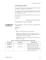
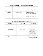
Page 83: ...onfiguration Commands The general forms of a Configuration Command are displayed in Table A 2 and Table A 3 AAd CRLF where AA is the command field and is always capitalized d represents an argument wh...

Page 84: ...Lhhmmss CRLF Displays current SAMPLE INTERVAL in hours minutes seconds Table A 2 Command Set for Displaying Current Configuration COMMAND RESPONSE DESCRIPTION Table A 3 Command Set for Configuration...

Page 85: ...eed CRLF Table A 4 Particle Counter Setup Commands COMMAND RESPONSE DESCRIPTION L ENTER Lhhmmss CRLF Queries the instrument s Sample Interval displayed in hours minutes seconds Lhhmmss ENTER L Sets th...

Page 86: ...e Interval and then stop c c Start Count Start counting immediately Instrument counts until the Stop command e is sent Does not use Sample Interval d d Auto Manual Start Starts the counting in either...

Page 87: ...ase the buffers on all the devices This command is not echoed uc Universal Immediate Start Computer Controlled The devices start counting and continue to count until a Stop command is sent from the co...

Page 88: ...er is empty and is not followed by CRLF B B data record CRLF or B Send Current Record Sends the data record of the most recent sample interval in the Rotating Buffer The record is NOT erased from the...

Page 89: ...DESCRIPTION E E Version number CRLF Eeprom Version Queries instrument for its firmware version number The version number is a variable length string containing alphanumeric and punctuation characters...

Page 90: ...are separated with spaces The first character in the response is the echoed command This character is not included in the Checksum value Figure A 1 shows the data format of a record for an eight chan...

Page 91: ...ld separators Date The Date is carried in characters 3 through 8 formatted as MMDDYY Time Time information is in characters 10 through 15 Time is expressed in 24 hour format as HHMMSS Sample Interval...

Page 92: ...ount is six characters and indicates the number of particles counted during Interval at the size range Location Where multiple instruments are connected to an RS 485 bus each unit must have a unique i...

Page 93: ...ted MODBUS Commands See www modbus org for documentation on how to use these commands Table B 1 MODBUS Communications Settings Baud Rate 19200 Data Bits 8 Stop Bits 1 Parity None Hardware Protocol RS4...

Page 94: ...eger Device Status bit 0 RUNNING bit 1 SAMPLING bit 2 NEW DATA bit 3 DEVICE ERROR 40004 unsigned integer Firmware version Major version digits are hundreds Minor version digits are tens and ones For e...

Page 95: ...es 1 6 for the MiniManifold Controller moves the arm to that position on the manifold Value 0 moves arm to Home position 40027 signed integer Real Time Clock RTC high Updates instrument s real time cl...

Page 96: ...teger Laser Reference Voltage millivolts 40040 unsigned integer View Volume Divide by 100 to get percentage For example 6550d 65 50 40041 ASCII string Flow Unit Defines unit as cfm lpm mlpm char 0 cha...

Page 97: ...en this register is read it always returns a zero Table B 4 Device Status Bit Description 0 RUNNING Set when a start command is executed remotely via Command 9 manual start or Command 11 instrument st...

Page 98: ...pump if applicable perform after 10 below 9 Manual Start The instrument samples continuously until it receives a Manual Stop command Ignores local timing parameters Sets Sample Time for data record to...

Page 99: ...ne data record in the device The Record Index Register 40025 must be changed to index other records here The first record in the data buffer is located at Index 0 The most recently saved value is at I...

Page 100: ...Data Status Byte are flagged to indicate particular conditions of the currently indexed data record If multiple states occur the bits are added together For example a Flow Alert and a Particle Overfl...

Page 101: ...series is used to identify the type of data items in the 30xxx series The Data Type registers run in parallel with the Data Registers For example Data Register 30041 s Data Type register is 41041 Data...

Page 102: ...to identify particle channel sizes and are always expressed in microns These types represent raw counts only Table B 8 Data Types String Description TIME Timestamp STIM Sample Time SVOL Sample Volume...

Page 103: ...e sent by the device Some of these units are not currently used but are reserved for future use Table B 10 Data Units Units Description Units Description Count For Particles ft m Feet per minute Perce...

Page 104: ...n in parallel with the data registers 30xxx series For example data register 30010 s enable register would be 43010 Data register 30016 s enable register would be 43016 Note Alarm Enable currently onl...

Page 105: ...annel 5 high 43018 unsigned int Enable for Particle Channel 5 low 43019 unsigned int Enable for Particle Channel 6 high 43020 unsigned int Enable for Particle Channel 6 low 43021 unsigned int Enable f...

Page 106: ...write All threshold data items are 4 bytes long and are stored across 2 registers Byte and word ordering is big endian Thus data items are formed by placing the high bytes in front of the low bytes Fo...

Page 107: ...unsigned int Threshold for Particle Channel 1 low 45011 unsigned int Threshold for Particle Channel 2 high 45012 unsigned int Threshold for Particle Channel 2 low 45013 unsigned int Threshold for Par...

Page 108: ...lue The Alarm Threshold Value is set in the low register of the channels Table B 15 Alarm Threshold Registers set to default value Registers Particle Channel Threshold Value 45009 45010 1 1000 45011 4...

Page 109: ...included in the RLPC package 1 Turn off power to the RLPC and disconnect all cables 2 Stop liquid flow to the RLPC 3 Wrap a towel around the outlet nozzle to prevent liquid from spilling on the sensor...

Page 110: ...nd reconnect the flare tubing to the Inlet and Outlet Nozzles 10 Make sure that all tubing connected to the RLPC are securely connected WARNING Do NOT allow any liquid that has been used to flush the...

Page 111: ...anties and remedies granted under this Section may at LWS s option be terminated C THE FOREGOING WARRANTY IS EXCLUSIVE AND IN LIEU OF ALL OTHER REPRESENTATIONS WARRANTIES AND COVENANTS EXPRESS OR IMPL...

Page 112: ...Lighthouse REMOTE Liquid Particle Counter MODBUS Output Operating Manual D 2 248083227 1 Rev 8...

Page 113: ...tomatic Mode 7 2 B big endian data B 6 C Calibration 2 7 RLPC 0 1 m 2 3 RLPC 0 2 m 2 4 RLPC 0 3 m 2 5 RLPC 0 5 m 2 6 Channel Thresholds RLPC 0 1 m 2 3 RLPC 0 2 m 2 4 RLPC 0 3 m 2 5 RLPC 0 5 m 2 6 Chem...

Page 114: ...Version E 6 15 Enable Alarming 7 7 B 13 Enclosure RLPC 0 1 m 2 3 RLPC 0 2 m 2 4 RLPC 0 3 m 2 5 RLPC 0 5 m 2 6 Environmental Sensors RLPC 0 1 m 2 3 RLPC 0 2 m 2 4 RLPC 0 3 m 2 5 RLPC 0 5 m 2 6 Externa...

Page 115: ...Input Requirements RLPC 0 1 m 2 3 RLPC 0 2 m 2 4 RLPC 0 3 m 2 5 RLPC 0 5 m 2 6 Programming with MODBUS Protocol 7 1 Programming with MR Protocol 6 1 R Real Time Clock Setting 7 3 Register Map B 2 Ret...

Page 116: ...C 0 2um 2 4 RLPC 0 3 m 2 5 RLPC 0 5 m 2 6 RLPC Chemical Compatibility 2 7 Storage Temp RH RLPC 0 1 m 2 3 RLPC 0 2 m 2 4 RLPC 0 3 m 2 5 RLPC 0 5 m 2 6 Summary of ASCII Configuration Commands 5 5 Suppor...

Page 117: ...00...

Page 118: ......

Reviews: