Controls
Operation & Maintenance Manual 23
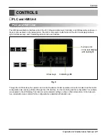
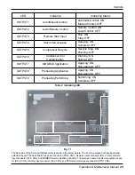
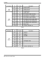
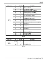
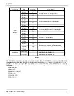
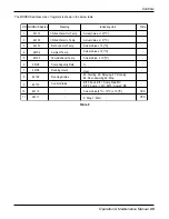
The back side of the PLC and HMI assembly is shown in the below picture. The PLC is composed of base board and
extension board. The base board has power connector (POW: CN1), discrete output connector (DO-1: CN2), discrete
input connector (DI-1: CN4), and MODBUS communication connector. The extension board has discrete output connec-
tor (DO-2: CN3), discrete input connector (DI-2: CN5), and RTD temperature input connector (RTDI: CN6).
LED
OUTPUT1
Auto/Manual Control
Automatic Control: ON
Manual Control: OFF
OUTPUT2
Local/Remote Control
Remote Control: ON
Local Control: OFF
OUTPUT3
Remote Start Input
Run: ON
Stop: OFF
OUTPUT4
Start Interval Lapse
Delaying: ON
Complete: OFF
OUTPUT5
Compressor Recycle
Recycle Stop: ON
Running: OFF
OUTPUT6
Condenser Coil
Warning: ON
Contamination
Normal: OFF
OUTPUT7
MODBUS Application
Applying: ON
Non-applying: OFF
OUTPUT8
Preheating Application
Applying: ON
Non-applying: OFF
OUTPUT9
Preheating Performing
Performing: ON
Complete: OFF
Indication
Indicating Status
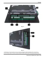
POW: CN1
DO - 1: CN2
DI - 1: CN4
DO - 2: CN3
DI
- 2: CN5
RTDI: CN6
Fig. 11
Table 2. Indicating LED

