General
16 Chiller Air-cooled Screw
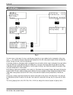
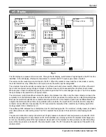
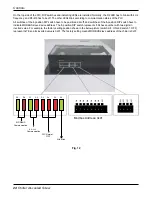
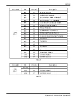
The liquid flow switch detects chilled water flow, and the water flow must build during running the chiller. The openness
of the switch during starting up or running compressor is considered to be water flow alarm by the PLC.
The DP switch means differential pressure switch input to the PLC. Normally, the switch must be closed when the com-
pressor runs. The switch opens when the differential pressure between condenser and evaporator is lower than the set-
ting value even with running compressor. The PLC considers the openness of the switch with running compressor to be
differential pressure alarm.
The overload switch is compressor internal protector that measures the temperature of motor winding and compressor
discharge. When any of the temperatures exceeds predetermined value, the switch opens. The PLC considers the
openness of the switch to be compressor overload alarm.
The fan contactor inputs are interconnected with their own overload relay contact, so they must be closed with running
fans.
The emergency stop switch must be closed, when the emergency switch is in normal position. When the switch is
pushed by operator, the emergency stop switch opens and all output from the PLC are disconnected. The PLC consid-
ers the openness of the switch to be emergency alarm.
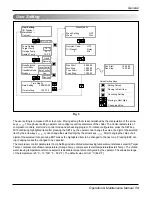
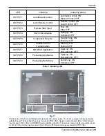
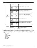
The discrete outputs generated from the PLC are also displayed on the screen cut.
Alarm means the alarm notification to external devices by the PLC. If any system alarm is detected by the PLC, the
alarm will be closed by the PLC.
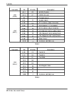
Main contactor, M2 contactor, and M3 contactor are outputs to the magnetic contactors for the compressor. When the
compressor starts, main contactor(M1) and M3 contactor are energized to start the compressor with star winding topolo-
gy. After a few seconds, the winding topology is changed into delta topology by de-energizing the M3 and energizing M2
instead. During running the compressor, the main contactor and the M2 contactor hold to be energized.
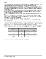
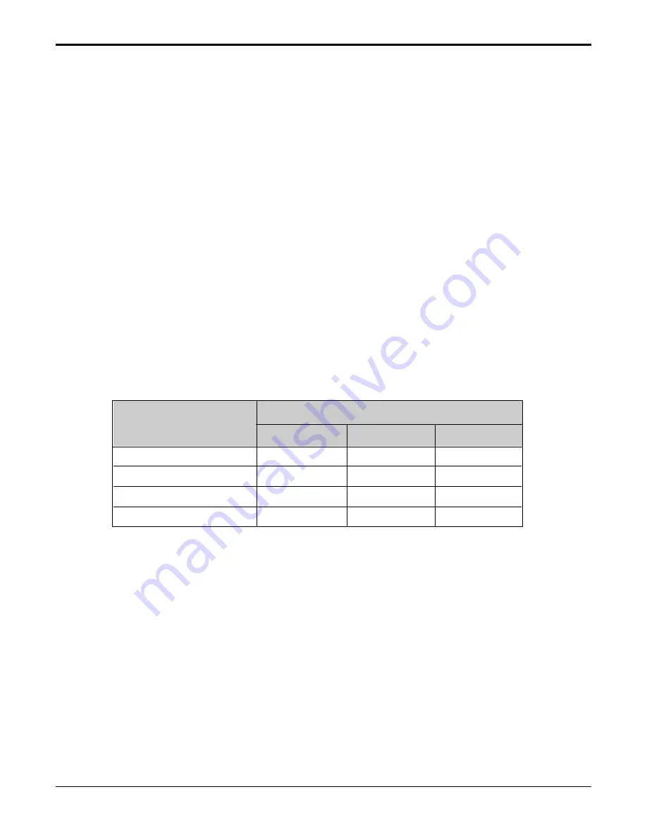
The 25% mgv, 50% mgv, and 75% mgv represent outputs to magnet valves for compressor loading. The magnet valves
are installed on the compressor. The capacity control by the control of the magnet valves is shown in the below table.
The fan outputs are outputs to the magnetic contactors of the fans by the PLC.
Step
100%
Off
Off
Off
75%
On
Off
Off
50%
Off
On
Off
MINIMUM
Off
Off
On
Magnet Valve
75%
50%
25%
Table 1

