Service
Operation & Maintenance Manual 43
■
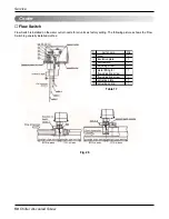
Cycle Components
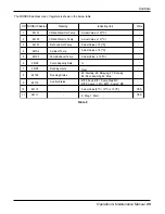
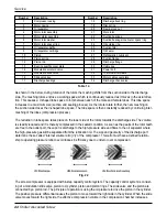
The structure of the air-cooled cooling cycle is shown in the below.
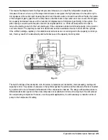
The unit is equipped with semi-hermetic screw compressor developed especially for applications in air-condi-
tioning. The construction of the compressor is shown in the below.
SERVICE
No.
PART
No.
PART
No.
PART
No.
PART
(1)
Compressor
(7)
Flow Control Device
(13)
Oil Level Switch
(19)
Relief Valve
(2)
Condenser
(8)
Flow Control Device
(14)
Oil Solenoid Valve
(20)
Temperature Sensor
(3)
Reciever
(9)
Dryer
(15)
Oil Flow Switch
(21)
Low Pressure Switch
(4)
Oil Filter
(10)
Evapolator
(16)
Discharge Temp. Sensor
(22)
Water Flow Switch
(5)
Oil Seperator / Economizer
(11)
Oil Heater
(17)
Oil High Pressure Switch
(23)
Ref. Solenoid Valve
(6)
Flow Control Device
(12)
Oil Level Sight Glass
(18)
Anti-freezing Switch
(24)
Check Valve
Compressor
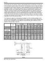
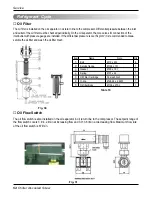
Table 13
Fig. 21
Fig. 20

