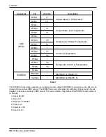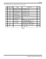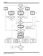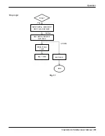
Controls
24 Chiller Air-cooled Screw
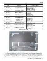
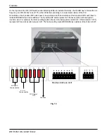
On the top side of the PLC, DIP switches and indicating LEDs are installed. Normally, the D2 LED has to blink with 4 Hz
frequency, and D3~D6 has to be off. The other LEDs blink according to communication status of the PLC.
All switches of the 4-position DIP switch have to be positioned at off, and switches of the 8-position DIP switch have to
indicate MODBUS slave device address. The 8-position DIP switch represents 8 bit hexa number with two digits in
inverted value. For example, the factory setting position shown in the below picture (switch2~8: ON and switch 1: OFF)
represent 0x7E and its inverted value is 0x01. The factory setting means MODBUS slave address of the chiller is 0x01:
D2
D3
D4
D5
D6
D7
D8
D9
1
2
3
4
1
2
3
4
ON
ON
ON
ON
ON
ON
ON
OFF
OFF
OFF
OFF
OFF
5
6
7
8
Modbus Address: 0x01
MODBUS
Communication
RS
-
232
Communication
PLC Normal:
OFF
4Hz Blink
Fig. 12

