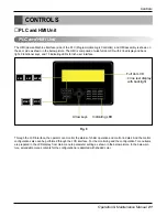
Controls
22 Chiller Air-cooled Screw
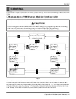
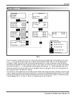
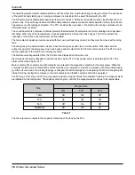
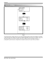
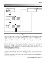
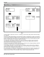
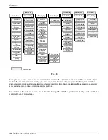
Among the menu items, some items are protected from access with authorization code system. The user setting is pro-
tected with user code, and delay setting, system setting, and parameter setting are protected from system code. The
dual authorization code system enables only authorized operators to configure operation settings, and also enable only
service engineers to configure control parameter settings.
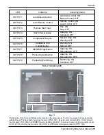
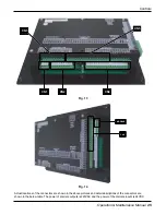
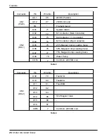
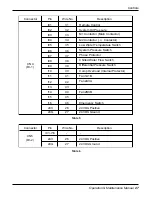
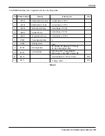
The functions of the LEDs are shown in the below table. Through the LED, the operators can identity the status of chiller
control without any manipulation.
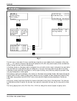
Fig. 10
Main Menu
User Setting
I/O Display
Alarm Display
System Setting
Para. Setting
Delay Setting
Hand/Auto
Mode
Control Mode
Start Interval
Expiration
Chilled Water
In Temp
Ambient
Temp
Exhaust
Temp
Chilled Water
Out Temp
Condensate
Temp
Comp
Running Hour
Running
Capacity
Target Temp
Outage Temp
Restart Temp
Hand/Auto
Mode
System Clock
Control Mode
Oil Preheating
Delay
Schedule
Program
Amendable Item
Remote
Control Input
Oil Check
System Input
Comp Contactor
Contact Inputs
Low Temp
Switch Input
Pressure
Switch Input
Phase
Protect Input
Chilled Water
Flow Input
Differential
Pressure Input
Compressor
Overload Input
Fan Contactor
Contact Inputs
Emergency
Switch Input
Alarm
Output
Comp Contactor
Outputs
Solenoid Valve
Output
Fan Contactor
Outputs
Pump Output
Alarm Clear
Current Alarms
Protected with
User Code
Protected with
System Code
Protected with
System Code
Protected with
System Code
Chilled Water In
Temp Amending
Chilled Water Out
Temp Amending
Cond Ref Out
Temp Amending
Ambient
Temp Amending
Comp Discharge
Temp Amending
Comp Running
Hour Clear
Fan Control
Transition Temp
Fan Load
Interval
Comp Discharge
Temp Hi Limit
Chilled Water Out
Temp Hi Ovrd
Outage Temp
Restart Temp
Start Interval
Comp Start
Delay
Comp Stop
Delay
Oil Preheat
Delay
Fan Control
Feedback
Comp Control
Feedback
System Code
Comp Overload
Delay
Differential
Pressure Delay
Fan Shutdown
Delay
Discharge Temp
Delay
MODBUS
Usage
System Clock
Status Message
Control Mode
MODBUS
Usage
User Code
Comp Loading
Valve Outputs

