SHINDAIWA OWNER’S/
OPERATOR’S MANUAL
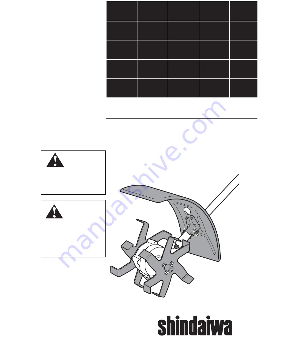
TILLER/CULTIVATOR
ATTACHMENT
Always wear eye and
ear protection when
operating this unit!
WARNING!
To minimize the risk of
injury to yourself and
others, read this manual
and familiarize yourself
with its contents.
WARNING!
Part Number 80465
䊛


