6.4
Section 6
Lubrication System
7. Fill the crankcase with new oil of the proper type
to the
F
mark on the dipstick.
8. Start the engine and check for oil leaks. Correct
any leaks before placing the engine into service.
Check oil level to be sure it is up to but not over
the
F
mark.
Service Oil Cooler
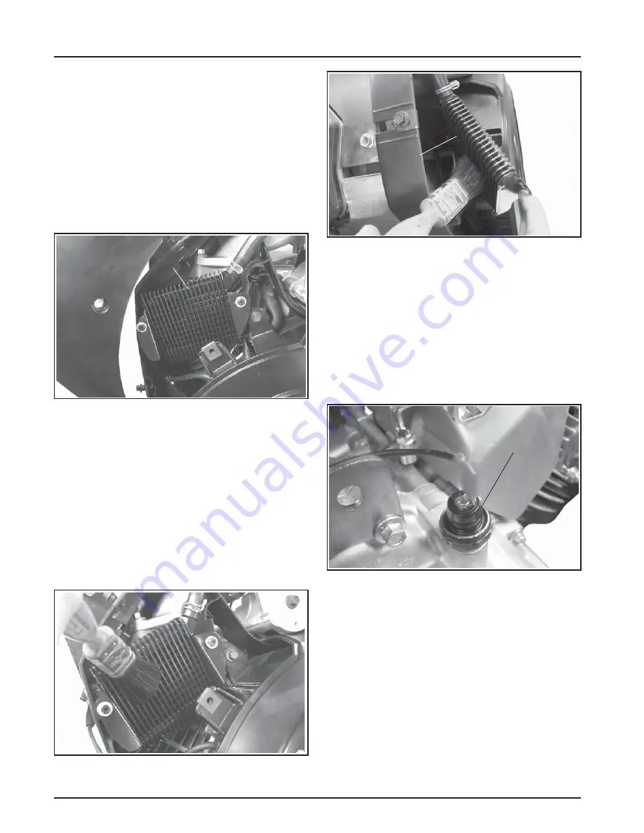
These engines are equipped with an oil cooler
mounted under the No. 2 side cylinder shroud,
separate from the oil
fi
lter. See Figure 6-9.
Oil
Cooler
Cylinder
Shroud
Figure 6-9. Oil Cooler.
Inspect and clean the oil cooler every
150 hours of
operation
(more frequently under severe conditions).
In order to be e
ff
ective, the oil cooler must be kept free
of debris.
To service the oil cooler, clean the outside of
fi
ns
with a brush, vacuum, or compressed air. If required,
remove the two screws holding the cooler unit to the
backing shroud assembly. Carefully pull the cooler
outward and clean the underside. A
ft
er cleaning,
reinstall the oil cooler to the backing shroud with the
two mounting screws.
Figure 6-10. Cleaning Top of Oil Cooler.
Oil
Cooler
Figure 6-11. Cleaning Underside of Oil Cooler.
Oil Sentry™
General
Some engines are equipped with an optional Oil
Sentry™ switch. This switch is designed to prevent
the engine from starting in a low oil or no oil
condition. The Oil Sentry™ may not shut down
a running engine before damage occurs. In some
applications this switch may activate a warning signal.
Read your equipment manuals for more information.
Pressure Switch
Pressure Switch
Figure 6-12. Oil Sentry™ Pressure Switch.
Installation
The Oil Sentry™ pressure switch is installed in
the closure plate pressure port. See Figure 6-12.
On engines not equipped with Oil Sentry™ the
installation hole is sealed with a 1/8-27 N.P.T.F. pipe
plug.
To install the switch, follow these steps:
1. Apply
pipe sealant with Te
fl
on
®
(Loctite
®
592™
PST
®
Thread Sealant or equivalent) to the threads
of the switch.
2. Install the switch into the tapped hole in the
closure plate. See Figure 6-12.
Summary of Contents for Comand Pro CH1000
Page 1: ...SERVICE MANUAL HORIZONTAL CRANKSHAFT CH940 CH1000...
Page 2: ......
Page 4: ......
Page 30: ...4 4 Section 4 Air Cleaner and Air Intake System...
Page 52: ...6 6 Section 6 Lubrication System...
Page 96: ...8 16 Section 8 Disassembly...
Page 110: ...Section 9 Inspection and Reconditioning 9 14...
Page 140: ...10 30 Section 10 Reassembly...
Page 141: ......


