5.8
Section 5
Fuel System and Governor
Carburetor Servicing
The following section covers the disassembly,
various servicing procedures, and reassembly of
the carburetor. For each procedure carefully inspect
all components and replace those that are worn or
damaged. The following should also be noted as
service is performed.
• Inspect the carburetor body for cracks, holes, and
other wear or damage.
• Inspect the
fl
oat for cracks, holes, and missing
or damaged
fl
oat tabs. Check the
fl
oat hinge and
sha
ft
for wear or damage.
• Inspect the fuel inlet needle and seat for wear or
damage.
• The choke plate is spring loaded. Check to make
sure it moves freely on the sha
ft
.
NOTE: The main and slow jets are
fi
xed and side
speci
fi
c and can be removed if required.
Fixed jets for high altitudes are available.
Float Replacement
If symptoms described in the carburetor
troubleshooting guide indicate
fl
oat level problems,
remove the carburetor from the engine to check and/
or replace the
fl
oat. Use a
fl
oat kit to replace the
fl
oat,
pin,
fl
oat valve, clip, and screw.
1. Perform the removal procedures for the
appropriate air cleaner and the carburetor
outlined in Section 8
Disassembly
.
2. Clean the exterior surfaces of dirt or foreign
material before disassembling the carburetor.
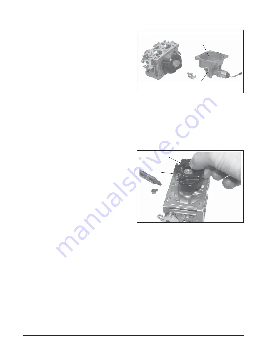
Remove the four mounting screws and carefully
separate the fuel bowl from the carburetor. Do
not damage the fuel bowl O-rings. Transfer any
remaining fuel into an approved container. Save
all parts. Fuel can also be drained prior to bowl
removal by loosening/removal of the bowl drain
screw. See Figure 5-12.
Figure 5- 12. Fuel Bowl Removed From Carburetor.
3. Remove the
fl
oat pin screw and li
ft
out the
old
fl
oat, pin and inlet needle. See Figure 5-13.
Discard all of the parts. The seat for the inlet
needle is not serviceable, and should not be
removed.
4. Clean the carburetor bowl and inlet seat areas as
required, before installing the new parts.
Figure 5-13. Removing Float and Inlet Needle.
5. A
tt
ach the inlet needle to the plastic tang of
the
fl
oat with the wire clip. The formed 90° lip
should point up, with the needle valve hanging
down. See Figure 5-14.
Fuel Bowl
Bowl Drain Screw
Float
Inlet
Needle
Summary of Contents for Comand Pro CH1000
Page 1: ...SERVICE MANUAL HORIZONTAL CRANKSHAFT CH940 CH1000...
Page 2: ......
Page 4: ......
Page 30: ...4 4 Section 4 Air Cleaner and Air Intake System...
Page 52: ...6 6 Section 6 Lubrication System...
Page 96: ...8 16 Section 8 Disassembly...
Page 110: ...Section 9 Inspection and Reconditioning 9 14...
Page 140: ...10 30 Section 10 Reassembly...
Page 141: ......


