background image

KGP-920 

                Chapter 8  

Setup Procedure 

93121662-00 


8-15 

8.5    Menu 8: Initial setting 

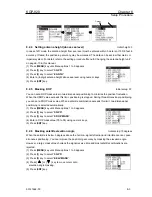
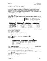
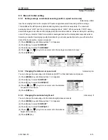
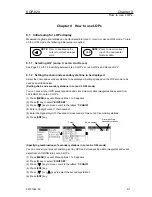
8.5.1    Setting average constants(measuring position, speed and course) 


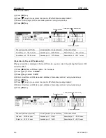
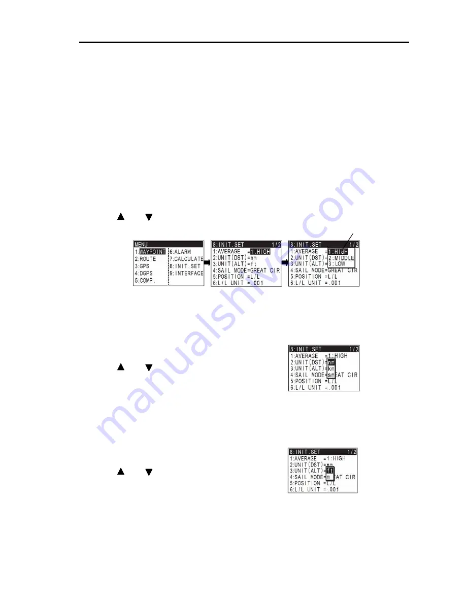
Initial setup: HIGH 

Use the averaging function to compare GPS sensor signals several times and get their average. 

This stabilizes the GPS position (latitude and longitude), speed and course data. The maximum 

averaging rate is “LOW” and the minimum averaging rate is “HIGH”. When you select “LOW” value, 

data is averaged more often and the display data has smaller variations. However, delays for updating 

occur. When you select a “HIGH” value, data is averaged less but the display data responds quicker. 

Selecting a constant (averaging constant) suitable for your boat speed will provide you with smoother 

data of the boat position, course and speed. 

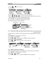
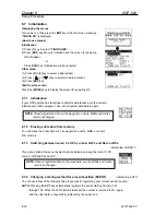
(1) Press [

MENU

] key until Menu options 1 to 9 appears.


(2) Press [

8

] key to select “

8:INIT.SET

”. 

(3) Press [

1

] key to select “

1:AVERAGE

”. 

(4) Press [        ] or [        ] key to move cursor onto the average constants to choose”. 

(5) Press [

ENT

] key. 


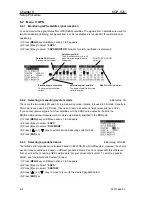
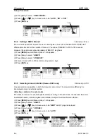
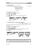
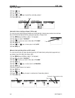
8.5.2    Changing the distance or speed unit

                                                                Initial setup: nm 

You can change the measuring unit of distance (to WPT or final destination) and speed. 

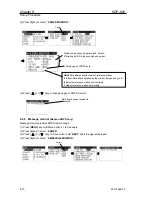
(1) Press [

MENU

] key until Menu options 1 to 9 appears.


(2) Press [

8

] key to select “

8:INIT.SET

”. 

(3) Press [

2

] key to select “

2:UNIT(DST)

”. 

(4) Press [        ] or [        ] key to move cursor onto the distance 

or speed unit to choose. 

(5) Press [

ENT

] key. 


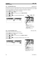
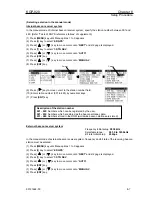
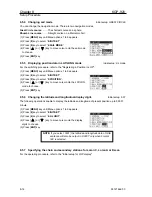
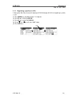
8.5.3    Changing the antenna height unit

                                                                        Initial setup: ft 

You can change the measuring unit of antenna height (above sea level). 

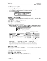
(1) Press [

MENU

] key until Menu options 1 to 9 appears.


(2) Press [

8

] key to select “

8:INIT.SET

”. 

(3) Press [

3

] key to select “

3:UNIT(ALT)

”. 

(4) Press [        ] or [        ] key to move cursor onto the antenna   

height unit to choose. 

(5) Press [

ENT

] key. 


Cursor 

Summary of Contents for KGP-920

Page 1: ......

Page 2: ...CLARATION 9 10 11 12 13 14 15 16 17 18 19 20 Amendment policy When any change is applied in the document only the document number of the relevant sheet s and cover sheet are modified and the rest of t...

Page 3: ...he unit after long periods of use Allergies can result from the inhalation of this dust therefore during inspection and cleaning it is advisable to use a mask z Static Electricity Static sensitive sem...

Page 4: ...Warning High Voltage mark Prohibition mark To handle the equipment ignoring this sign may lead to injury to the human body or damage to the equipment Alarm To handle the equipment ignoring this sign m...

Page 5: ...equirement Chapter 1 General Information About GPS Outline of the equipment Equipment composition Software type name Chapter 2 Equipment Composition Standard equipment list Optional items list Chapter...

Page 6: ...navigation Cross track error and course deviation angle Storing and erasing route Route setup Setting an anchor position Track display Chapter 7 Alarms Kinds of alarms Alarm explanation Setting and ca...

Page 7: ...ble shooting Chapter 11 Technical Reference Digital interface IEC 61162 1 second edition Chapter 12 Communication with external navigation system Changing to the EXTERNAL mode Route data transfer Anne...

Page 8: ...00 Contents Chapter 1 General Information Page No 1 1 About GPS 1 1 1 1 1 General 1 1 1 1 2 Positioning by GPS 1 1 1 1 3 Time required for position fix 1 1 1 2 Outline of the equipment 1 2 1 3 Equipm...

Page 9: ...your position latitude longitude and height is determined at the intersection point of four spheres formed by four satellites 1 1 3 Time required for position fix In the following circumstances your G...

Page 10: ...ion MSC 112 73 and IEC technical standards shown below z IEC 60945 4th Edition 2002 08 General z IEC 61108 1 Ed 2 0 2003 07 Ship borne GPS Receiver z IEC 61162 1 2nd Edition Digital Interface 1 3 Equi...

Page 11: ...plotter GTD 110 150 Radar Plotter MDP 600series MDP 1200series Echo sounder CVS 841series CVS 842 852series Plotter sounder CVG 80 200 Marine radar MD 3420 3441series MD 3641 3642series MD 3840series...

Page 12: ...KGP 920 Chapter 2 Equipment Composition 93121662 00 Contents Chapter 2 Equipment Composition Page No 2 1 Standard equipment list 2 1 2 2 Option items list 2 1...

Page 13: ...5m 04 CW 374 1 10M A 6 pin water resistant connector and a 6 pin connector w EMI core 10m 05 CW 376 1 5M 5m 06 CW 376 1 10M A 6 pin water resistant connector and other end plain w EMI core 10m 07 CW...

Page 14: ...KIT Receiver PCB connector harness install at the factory 22 BA 02 K 0 85kg 10m 23 BA 02L K 0 81kg 15m 24 Beacon antenna coupler Electric field type BA 02S K With antenna cable with a connector 0 47kg...

Page 15: ...0 Contents Chapter 3 Specifications Page No 3 1 GPS receiver 3 1 3 2 Display section 3 1 3 3 Data Input Output 3 1 3 4 Power requirements 3 2 3 5 Compass safe distance 3 2 3 6 Environmental conditions...

Page 16: ...od elapsed time altitude distance bearing cross track error course deviation time to go to waypoint total time to go and distance on route DOP value present time UTC or LTC satellite status beacon rec...

Page 17: ...ration The equipment operates normally under the following vibrating conditions 2 5 Hz 13 2 Hz Amplitude 1mm 10 Maximum acceleration of 7 m s2 at 13 2 Hz 13 2 Hz 100 Hz Maximum acceleration of 7 m s2...

Page 18: ...KGP 920 Chapter 3 Specifications 93121662 02 3 3 Figure 3 1 The Exterior of KGP 920 with dimensions Figure 3 2 Service space required for KGP 920 Unit mm inch Unit mm inch...

Page 19: ...with cable 10m GA 08L with cable 15m GA 08S with cable 0 5m for extension Figure 3 4 The Exterior of DGPS antenna unit option with dimensions Weight Without cable 0 92kg BA 03 1 4kg BA 03L 1 6kg BA 0...

Page 20: ...Display unit installation 4 1 4 5 1 Table mounting 4 1 4 5 2 Flush mounting 4 3 4 6 Antenna unit installation 4 4 4 6 1 Selecting the best site of GPS Beacon antenna 4 4 4 6 2 Fixing the antenna unit...

Page 21: ...g the units To achieve best operational performance the following factors must be considered 1 The display unit should be positioned in the location where the external situation can be viewed 2 Locate...

Page 22: ...Chapter 4 KGP 920 Installation 4 2 0093121662 08 Figure 4 1 Fitting detail of KGP 920 in table mounting mode Figure 4 2 Service space required for KGP 920...

Page 23: ...splay unit onto the mounting bracket 3 Put the display on the flush mount and fix with two 2 slotted head screws 4 Put the display on the opening and fix with four 4 tapping screws In case you use M4...

Page 24: ...ersed L type TX antenna 4 At least 1 meter 3 3 feet away from the receiving antenna 5 Outside radar transmitting beam 30 to 40 6 At least 1 meter 3 3 feet away from the radar antenna 7 At least 5 mete...

Page 25: ...n of 30m or 60m is possible by the antenna and extension cable of an option Case1 Case2 Antenna unit GA 08 GA 08L GA 08S Antenna unit GA 08 GA 08L GA 08S Hose clamp Option Screw 1 14UNS 2B Mast pole n...

Page 26: ...alf to 3 plies When winding is completed apply gentle pressure over the surface with fingers to expedite the fusion 2 Apply windings of PVC tape to reinforce the protection PVC tape should not be stra...

Page 27: ...arine radar Echo sounder Auto pilot AIS Other brand Echo sounder CVS 833series 100 115VAC 200 230VAC Grounding Wire not supplied 10 8 31 2VDC DC Power cable CW 267 1 8M Option Power rectifier PS 003A...

Page 28: ...W 376 1 5M 10M Option CW 376 1 5M 10M Option CW 376 1 5M 10M Marine radar MD 3420 3441series MD 3641 3642series MD 3840series MDC 3560 3510series Option CW 154A 5M Marine radar MDC 1800series Option C...

Page 29: ...XD 5 RXD 6 15V DATA 1 5 6 2 3 4 DATA 2 1 GND SHILD 2 TXD 3 TXD 4 RXD 5 RXD 6 BUZZER STP 7 BUZZER STP 8 EXT BUZZER 1 5 6 2 3 4 7 8 POWER 1 DC 2 F GND 3 DC 1 3 2 General data output RXD is used only mai...

Page 30: ...is RS 422 When CW 398 are used This port is an only for external alarm system ACK ALR output signal level is RS 422 and EXT BUZZER out put can drive a relay 24V 10mA BUZZER STP is an input port for s...

Page 31: ...ntrast and brightness 5 2 5 4 Selecting the screen 5 3 5 4 1 A NAV1 screen 5 3 5 4 2 B NAV2 screen 5 4 5 4 3 C NAV3 screen 5 5 5 4 4 D PLOT screen 5 5 5 5 String present position EVENT 5 7 5 5 1 AUTO...

Page 32: ...n Stores event positions Recalls memory position entry of numerical values and selection North or South latitude or East or West longitude Turns the power on and changes the brightness of control pane...

Page 33: ...seconds to turn NAVIGATOR off All data before power off is kept in memory for later use PWR DIM Press to change the LCD brightness in 5 levels CTRS Press to change the LCD contrast in 8 levels Blinks...

Page 34: ...ion waypoint and memory position 5 4 1 A NAV1 screen Standard Text mode Page 1 Page 2 NOTE Each following is each screen in the state where waypoint routes and anchor watch are not set up A screen whe...

Page 35: ...osition LAT LONG is displayed when displaying position data in Loran C Loran A or Decca LOPs mode Loran C Loran A or Decca LOPs is displayed when displaying position data in LAT LONG mode Present time...

Page 36: ...s failed to fix Your boat NAV3 screen shows a 3 dimensional view indicating the distance course cross track error and deviation from the waypoint The boat icon does not move in OFF mode Distance and b...

Page 37: ...Chapter 5 KGP 920 Basic Operation 5 6 93121662 00 Page 4 Close up of PLOT screen...

Page 38: ...1 Press MODE key until D PLOT screen appears 2 Press SEL key until page 6 screen appears 3 Press or key and move cursor onto the SYMBOL 4 Press ENT key to display symbol list 5 Press or key and move c...

Page 39: ...ur position is stored immediately and MOB screen appears You can see the distance and bearing from your present position to the point you pressed MOB key Proximity alarm blinking Alarm sounds when you...

Page 40: ...after you pressed MOB key NOTE The time display that is shown when the elapsed time has exceeded 99 minutes 59 seconds after the MOB key was pressed Speed in knots Course Present position NOTE You ca...

Page 41: ...lapsed time Course made good A true bearing from origin to present position Elapsed time The time elapsed after your power on or after you have pressed the CLR Reset key LAT LONG mode Example Data dis...

Page 42: ...een during waypoint navigation 6 6 6 2 7 D PLOT screen during waypoint navigation 6 6 6 3 Cross track error and course deviation angle 6 7 6 3 1 Navigation graph of NAV2 screen 6 7 6 3 2 Electronic fa...

Page 43: ...ition symbol on PLOT screen 6 19 6 6 4 Reentering an anchor position 6 19 6 6 5 Canceling anchor position 6 19 6 6 6 B NAV2 screen during anchor position setup 6 20 6 6 7 C NAV3 screen during anchor p...

Page 44: ...below 3 5 3 8 1 8 0 N 1 3 9 4 2 9 9 0 E 6 1 2 Writing comment Try to use comments for often used positions Nine symbols are available If you set a symbol at the beginning of your comment the symbol is...

Page 45: ...using numeric keys The coordinates will appears 5 Press ENT key to enter the source point number 6 Enter a destination point number 200 to 399 using numeric keys The coordinates will appears Use anoth...

Page 46: ...8 You can enter up to 10 letters by repeating 6 and 7 steps 9 Press ENT key and decide of a comment 6 1 5 Erasing a single waypoint 1 Press MENU key until Menu options 1 to 9 appears 2 Press 1 key to...

Page 47: ...the new waypoint is selected the waypoint navigation to it will commence and the specified position along with the comment QUICK will be assigned to the position number 398 Old data is replaced with a...

Page 48: ...NAV3 or D PLOT screen appears 2 Press SEL key until page 5 screen appears 3 Press key to move cursor to the RESET letters 4 Press ENT key to cancel WPT setting 6 2 5 B NAV2 screen during waypoint navi...

Page 49: ...he parameters shown in the 1st 3rd and 4th pages of the D PLOT screen refer to D PLOT screen in OFF mode in page 8 They are used in the same manner Distance from present position from WPT WPT position...

Page 50: ...n angle Waypoint Course deviation angle Cross track error Steer to the left to get back to the original course Bearing to WPT Distance from present Position to WPT True north Origin Course Steering di...

Page 51: ...en you have sailed 2 nm sm km the present position indication moves toward you and the next 4 nm sm km are shown At point E You are sailing outside of course width Present position This marking moves...

Page 52: ...o 1 nm sm km 2 nm sm km and 4 nm sm km The WPT indication changes when the length exceeds 4 nm sm km At point J You have reached The waypoint At point I You are 0 5 nm sm km away from waypoint Waypoin...

Page 53: ...yed 4 Enter a route number 01 to 20 using numeric keys 5 Press ENT key to store the route number 6 Press key to move cursor to the forward or backward route setup column 7 Press SEL key to select the...

Page 54: ...ect 1 RTE EDIT Route Input screen is displayed 4 Enter a route number 01 to 20 using numeric keys 5 Press key to move cursor to the waypoint number you wish to erase Its data and comment if any are di...

Page 55: ...is displayed 4 Enter a route number 01 to 20 using numeric keys 5 Press ENT key to recall the route number 6 Press CLR key A confirmation message appears 7 If OK press ENT key to erase all points of...

Page 56: ...waypoint Use the following steps to start route navigation Select the reverse navigation only after you have reached the final destination or the route navigation may not work properly 1 Press MODE ke...

Page 57: ...ress MODE key until A NAV1 B NAV2 C NAV3 or D PLOT screen appears 2 Press SEL key until page 5 screen appears 3 Press or key to move cursor to RTE letters 4 Press ENT key 5 Enter a route number 01 to...

Page 58: ...Press SEL key until page 2 screen appears 3 Press key to display DST 4 Press key to display TDST 1 Press MODE key until B NAV2 C NAV3 or D PLOT screen appears 2 Press SEL key until page 4 screen appea...

Page 59: ...to go to the next Route point Total time to go can also be shown WPT position Page number Arrival time mm dd hh mm Blinks when position fix is unavailable Speed Present position Course Page number Ra...

Page 60: ...xt Route point WPT position Page number Bearing to the next Point Total distance Can also be shown NOTE To change a display page Press this key SEL For description of the parameters shown in the 1st 3...

Page 61: ...comment ANCW 1 Press MODE key until B NAV2 C NAV3 or D PLOT screen appears 2 Press SEL key until page 5 screen appears 3 Press or key to move cursor to the letters ANCW 4 Press ENT key Current positio...

Page 62: ...tters 6 Press ENT key 6 6 4 Reentering an anchor position You can reenter a new anchor position and start to calculate navigation While the 1st to 4th pages of either the A NAV 1 B NAV 2 C NAV 3 or D...

Page 63: ...Arrival time mm dd hh mm NOTE To change a display page Press this key SEL Time to go from Present position to anchor position WPT position Page number Arrival time mm dd hh mm Distance from present po...

Page 64: ...ress the EVT key to store the cross cursor position Note not the present ship s position 6 7 2 Screen scrolling You can scroll the PLOT screen pages 1 2 3 or 4 in any direction so that your ship is al...

Page 65: ...ion is setup Changing the event symbol To change the event symbol place cursor on SYMBOL option and press ENT key Activating event numbers 000 to 199 Turn ON the EVENT option and you can save events t...

Page 66: ...T DST of 8 INITIAL Turning tracking off Set the TRACK option to OFF to stop recording the track on PLOT screen Your present position marking moves on the screen Set the TRACK option to ON to record th...

Page 67: ...apter 7 Alarms Page No 7 1 Kinds of alarms 7 1 7 1 1 Anchor watch alarm ANCW 7 1 7 1 2 Proximity alarm PROX 7 1 7 1 3 Cross track error alarm XTE 7 2 7 1 4 Course deviation angle alarm CDI 7 2 7 2 Ala...

Page 68: ...alarm range 7 1 2 Proximity alarm PROX A proximity alarm alerts you when you arrive to within a preset distance to a waypoint The proximity alarm will not work if the alarm range is set to 0 00 Note y...

Page 69: ...se to steer by a predetermined margin The alarm function does not work if the alarm range is set to 00 CDI letters blink and buzzer long beep sounds when I m away from CDI range 7 2 Alarm explanation...

Page 70: ...Press 6 key to select 6 ALARM 3 Select item number of the alarm to be set from the numerical keypad 4 Press key to move cursor to alarm range field 5 Enter an alarm range by numeric key CDI alarm ran...

Page 71: ...8 5 8 3 3 DGPS measurement 8 5 8 3 4 Setting a DGPS timeout 8 6 8 3 5 Selecting a beacon station Beacon DGPS only 8 6 8 3 6 String a beacon station internal beacon receiver system only 8 8 8 3 7 Sele...

Page 72: ...f DATA port 8 17 8 6 2 Editing the IEC 61162 1 output data format of DATA port 8 17 8 6 3 Explanation of output data sentence 8 18 8 6 4 Selecting an output format of waypoint data 8 18 8 6 5 Selectin...

Page 73: ...itor beacon message NOTE You can select an option from Menu in two ways by direct numeric key entry and by cursor shifting This manual explains how to enter numeric values for easy understanding but y...

Page 74: ...e 2D mode 1 Press MENU key until Menu options 1 to 9 appears 2 Press 3 key to select 3 GPS 3 Press 2 key to select 2 FIX MODE 4 Press or key to select desired measuring system mode 5 Press ENT key 8 2...

Page 75: ...the HDOP value exceeds this limit positioning is stopped During three dimensional positioning you can set a PDOP mask value When a satellite combination exceeds this limit two dimensional positioning...

Page 76: ...to select desired RAIM function 6 Press ENT key 8 2 8 Selecting RAIM accuracy Initial setup 100m RAIM accuracy can be chosen from 100m and 10m 1 Press MENU key until Menu options 1 to 9 appears 2 Pre...

Page 77: ...GPS Initial setup BEACON BEACON DGPS for RTCM SC 104 SBAS WAAS EGNOS MSAS 1 Press MENU key until Menu options 1 to 9 appears 2 Press 4 key to select 4 DGPS 3 Press 1 key to select 1 DGPS STYLE 4 Press...

Page 78: ...T 4 Enter a timeout 010 to 180 seconds using numeric keys 5 Press ENT key 8 3 5 Selecting a beacon station Beacon DGPS only Initial setup AUTO A beacon station is selectable in both the manual or auto...

Page 79: ...ion number 001 to 480 by numerical keys 11 Press ENT key External beacon receiver system In the manual mode of external beacon receiver system frequency and bit rate of the receiving beacon station mu...

Page 80: ...ster up to 20 station numbers in the range of 001 to 020 1 Press MENU key until Menu options 1 to 9 appears 2 Press 4 key to select 4 DGPS 3 Press or key to move cursor onto NEXT and 2 2 page is displ...

Page 81: ...up 4800 bps Adjust the baud rate of RTCM SC 104 format signal reception to the output signal baud rate of beacon receiver 1 Press MENU key until Menu options 1 to 9 appears 2 Press 4 key to select 4 D...

Page 82: ...to select 4 DGPS 3 Press or key to move cursor onto NEXT and 2 2 page is displayed 4 Press 6 key to select 6 MESSAGE MONITOR Cursor Displays Frequency being received bit rate S N ratio and ID No beaco...

Page 83: ...200 is entered by pressing the following keys in exact order given below 3 5 3 7 7 0 0 N ENT 1 3 9 4 3 2 0 0 E ENT Present position Actual position to be entered Correction offset Latitude 35 o 37 89...

Page 84: ...3 Press 1 key to select 1 LAT LON 4 Press CLR key to set correction offset to 0 correction is disabled 8 4 4 Compensating the compass Initial setup Auto mode The course and bearing to waypoint is sho...

Page 85: ...t using numeric keys 10 Press ENT key 8 4 5 Displaying local time Initial setup 00 00 hour You can display your local time by entering a time difference from the Greenwich Mean Time GMT See the follow...

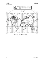
Page 86: ...3 4 5 6 7 8 9 10 11 11 10 9 8 7 6 5 4 3 2 1 0 1 2 3 4 5 6 7 8 9 10 11 Figure 8 1 Time difference chart 12 12 12 12 12 12 12 12 Greenwich Mean Time GMT International date line International date line N...

Page 87: ...ta of the boat position course and speed 1 Press MENU key until Menu options 1 to 9 appears 2 Press 8 key to select 8 INIT SET 3 Press 1 key to select 1 AVERAGE 4 Press or key to move cursor onto the...

Page 88: ...ptions 1 to 9 appears 2 Press 8 key to select 8 INIT SET 3 Press 5 key to select 5 POSITION 4 Press or key to move cursor onto the LAT LON mode to choose 5 Press ENT key 8 5 6 Changing the latitude an...

Page 89: ...You can select the output sentence and set the output cycle in seconds of the IEC 61162 1 output data format 1 Press MENU key until Menu options 1 to 9 appears 2 Press 9 key to select 9 INTERFACE 3 P...

Page 90: ...and distance from present position to waypoint approaching speed to waypoint proximity alarm Recommended Minimum Specific GPS TRANSIT Data UTC time lat long ground speed true bearing magnetic deviati...

Page 91: ...of IEC 61162 1 ACK Acknowledge alarm ALR Set alarm state Extension data port When IEC format is selected both DATA and DATA 2 ports output IEC format But when output format other than IEC is selected...

Page 92: ...system parameters again 8 7 2 Erasing entire data from memory You can erase the entire data such as waypoints events MOB and route from memory 8 7 3 Switching between Loran C LOPs Loran A LOPs and De...

Page 93: ...tude west longitude region as the initial value N E N Lat E Long When power is turned on GPS or DGPS position measurement is started using the north latitude east longitude region as the initial value...

Page 94: ...1 String a new position or updating an existing one 9 4 9 3 Correcting your position LOPs 9 5 9 3 1 Direct entry of actual position data 9 5 9 3 2 Entry of correction amount 9 7 9 3 3 Checking the co...

Page 95: ...tations in Loran C LOPs mode You can convert your GPS present position and stored memory data waypoints and events from LAT LONG into Loran C LOPs 1 Press MENU key until Menu options 1 to 9 appears 2...

Page 96: ...letters 7 CHAIN Cursor 4 Press ENT key 5 Press or key to move cursor onto AUTO 6 Press ENT key Manual chain selecting in Decca LOPs mode You can convert both your present position given by GPS and st...

Page 97: ...es the procedure for replacing LAT LONG display with LOP and registering a position in LOP 1 Press MENU key until Menu options 1 to 9 appears 2 Press 8 key to select 8 INIT SET 3 Press 5 key to select...

Page 98: ...a 6 digit data LOPs of secondary station 1 using numeric keys 8 Press ENT key 9 Enter a 6 digit data LOPs of secondary station 2 using numeric keys 10 Press ENT key Loran A LOPs mode 7 Enter a 5 digi...

Page 99: ...ss 2 key to select 2 LOP 4 Enter correct 6 digit LOPs of secondary station 1 using numeric keys 5 Press ENT key 6 Press key to move cursor to Loran C LOPs field of secondary station 2 7 Enter correct...

Page 100: ...correction offset 1 Press MENU key until Menu options 1 to 9 appears 2 Press 5 key to select 5 COMP 3 Press 2 key to select 2 LOP 4 Enter correct Decca LOPs lane and centilane of secondary station 1...

Page 101: ...e current positive or negative sign as it is 10 Enter correction offset 6 digit of secondary station 2 using numeric keys 11 Press ENT key Present position GPS fix Actual position to be entered Correc...

Page 102: ...t it by entering the Decca LOPs correction offset 1 Press MENU key until Menu options 1 to 9 appears 2 Press 5 key to select 5 COMP 3 Press 2 key to select 2 LOP 4 Press key to move cursor to correcti...

Page 103: ...check the correction offset as follows Correction data to be entered The correction offset 1 Press MENU key until Menu options 1 to 9 appears 2 Press 5 key to select 5 COMP 3 Press 2 key to select 2 L...

Page 104: ...ing numeric keys 8 Enter N for north or S for south latitude 9 Press ENT key 10 Enter a 8 digit longitude using numeric keys 11 Enter E for east or W for west latitude 12 Press ENT key If you store th...

Page 105: ...key 9 Press or key to select the secondary station 2 10 Press ENT key 11 Press key to move the cursor to latitude field 12 Enter a 7 digit latitude using numeric keys 13 Enter N for north or S for sou...

Page 106: ...er 5 Press ENT key 6 Press key to move the cursor to combination field of secondary stations 7 Press ENT key 8 Press or key to select a combination of secondary stations 9 Press ENT key 10 Press key t...

Page 107: ...ta number Data currently stored X L L LOP fixed CAUTION Do not use the converted LOPs position data for waypoint or route navigation because of likely conversion errors Accuracy of converted positions...

Page 108: ...ance and Trouble shooting Page No 10 1 Periodic inspection and cleaning 10 1 10 1 1 Monthly check 10 1 10 1 2 maintenance 10 1 10 2 Trouble shooting 10 1 10 2 1 Information required service 10 1 10 2...

Page 109: ...rial number 4 Next port of call ship s agent name fax number email address etc 5 Faulty conditions precisely as possible and the result of on board check 10 2 2 Trouble shooting The following table pr...

Page 110: ...n for better viewing range available Differential GPS DGPS Positioning fails 1 Are the baud rate you have set and the output signal baudrate of DGPS beacon receiver match See page 8 7 2 Are the elevat...

Page 111: ...turn the power off and then restart again GPS NO FIX 35 o 37 893N 141 o 05 719E 01 16 04 06 01 16 1 GPS NO FIX This message is that it became impossible to receive a GPS signal and when the positionin...

Page 112: ...age No 11 1 Digital interface IEC 61162 1 second edition 11 1 11 1 1 input data format DATA 2 port 11 1 11 1 2 Output data format DATA DATA 2 port 11 1 11 1 3 Output data specification 11 1 11 1 4 Out...

Page 113: ...tput level Output current Sentence Update rate 4800 RS422 20mA max AAM APB BOD BWC DCN DTM GBS GGA GLC GLL GNS GSA GSV MSS RMB RMC RTE VTG WPL XTE ZDA NOTE The sentences of bold character are set in 1...

Page 114: ...Destination waypoint ID A perpendicular passed at waypoint V perpendicular not passed A arrival circle entered V arrival circle not passed Direction to steer L R XTE units nautical miles Magnitude of...

Page 115: ...c x x A A A A x x N x hh CR LF Start of sentence Talker device Sentence type Fix data basis Position uncertainly n miles Purple line navigation use A valid V Data not valid Green line navigation use A...

Page 116: ...llite Standard deviation of bias estimate GP GGA hhmmss ss lllll lll a yyyyy yyy a x xx x x x x M x x M Sentence type Talker device Latitude N S Start of sentence UTC of position fix hr min sec Longit...

Page 117: ...e E W Antenna altitude m HDOP value Number of satellites in use 00 12 Age of differential data sec Differential reference station ID Geoidal separation m x x x x hh CR LF GP GLL lllll lll a yyyyy yyy...

Page 118: ...d or perpendicular passed V not entered or passed Origin waypoint ID Direction to steer L R Cross track error nautical miles A data valid V navigation receiver warning Range to destination nautical mi...

Page 119: ...Simulator N Data not valid GPRTE Course over ground and ground speed GP RTE x x x x a c c c c c c hh CR LF Waypoint n identifier Sentence type Talker device Start of sentence C complete route all way...

Page 120: ...tence V general warning flag for other navigation systems When a reliable fix is not available V LORAN C blink or SNR warning A data valid A data valid V LORAN C cycle lock warning flag Magnitude of c...

Page 121: ...ATA port output circuit Device Driver IC AM26C311 T I TXD TXD AM26C31I Vcc DATA 2 port input circuit Input load 470 2 4k ohm Device Photo coupler TLP181 Toshiba RXD TLP 181 Vcc 470 RXD Vcc BUZZER STP...

Page 122: ...Chapter 11 KGP 920 Technical Reference DATA 2 port output circuit Device Transistor 2SC2712 2SC2712 EXT BUZZER 11 10 93121662 00...

Page 123: ...cation with external navigation system Page No 12 1 Changing to the EXTERNAL mode 12 1 12 2 Route data transfer 12 2 12 2 1 Complete route transfer 12 2 12 2 2 Selecting route navigation 12 3 12 2 3 W...

Page 124: ...should be established by a connecting cable according to the operation manual Page 69 and 70 interconnecting Diagram 12 1 Changing to the EXTERNAL mode Communication with an external system such as EC...

Page 125: ...VERWRITING last sent route is indicated and then it indicates LOADED ext route to notify the route was successfully transferred When consecutive more than single routes are received It indicates INVAL...

Page 126: ...ty As far as KGP 920 receives Working route data within 10 seconds consecutively it continues to work for the received working route When waypoint is changed by reaching to the next waypoint or other...

Page 127: ...L 5411 81 N 00721 94 E WP_004 26 ECWPL 5414 39 N 00616 22 E myName 77 ECWPL 5417 69 N 00450 70 E WP_006 2B Max 10 waypoints Over10 is ignored Working route has priority and route navigation by Working...

Page 128: ...KGP 920 Annex Annex Page No Local Geodetic Systems A 1 Decca zone A 3 93121662 00 Contents...

Page 129: ...3 CORVO FLORES C F 65 NAD 83 N83 10 DIEGO GARCIA DEG 52 NEW GEORGIA NEG 46 DJAKARTE DJK 22 NEW ZELAND NEZ 13 EAST FALKLAND EAF 76 NIGERIA NIG 63 EAST MALAYSIA EAM 79 OMAN OMA 67 EASTER EST 47 PARAGUAY...

Page 130: ...Local Geodetic Systems A 2 Name Abbreviation No Name Abbreviation No SWEDEN SWE 85 TERN TER 33 TOKYO TOY 02 TRINIDAD TRD 64 TRISTAN TRI 80 TUNISIA TUN 42 WGS 72 W72 01 WGS 84 W84 00 HU TZU SHAN HTN 86...

Page 131: ...Salaya 42 2F Northwest Spanish 09 4C SOUTH AFRICA Trondelag 10 4E Southwest Africa 44 9C English 11 5B Natal 45 10C North Bothnian 12 5F South Spanish 13 6A North Scottish 14 6C Gulf of Finland 15 6E...

Page 132: ......

Reviews: