KLA Tencor P-16+ User Manual Download Page 94

Scan Recipes - Creating and Editing a Scan Recipe

KLA-Tencor P-16+ / P-6 User’s Guide 

3-46

KLA-Tencor Confidential

0142530-000 AB

3/13/09

The median filter is a major component of the Glitch Removal process used on data in 
the Analysis screen for both 2D and 3D data.

The available filter sizes (kernels) for 2D data are: 1 x 3, 1 x 5, and 1 x 7 points.

The available filter sizes (kernels) for 3D data are: 3 x 3, 5 x 5, and 7 x 7 points.

To add a filter or change the filter size on existing data, use the following procedure:

1.

From the Analysis screen, click 

Edit

 to display its menu.

2.

Select 

Recipe

. This opens the recipe used to generate the data. 
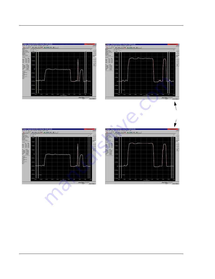
Figure 3.36

Median Filter Application in Glitch Removal

1 x 3

 point median filter 

before and after application

BEFORE APPLICATION

AFTER APPLICATION

1 x 7

 point median filter 

before and after application

BEFORE APPLICATION

AFTER APPLICATION

Notice how much smoother the 1 x 7 
filter (below) made the scan than that of 
the 1 x 3 filter (above).

Summary of Contents for P-16+

Page 1: ...ive Milpitas CA 95035 Phone 408 875 3000 FAX 408 571 2722 P 16 P 6 User s Guide KLA TENCOR CONFIDENTIAL Family Profiler Product Line Profiler P1X PX Model P 16 P 6 Software Version 7 31 7 35 MNL USER...

Page 2: ...P 6 User s Guide KLA TENCOR CONFIDENTIAL 0142530 000AB 3 13 09 TRADEMARKS P 16 P 6 is a trademark of KLA Tencor Corporation All other brand and product names may be trademarks of their respective comp...

Page 3: ...ety Standards EN 60204 1 1992 IEC 61010 1 2001 EN 61010 1 2001 2nd Edition EN 61000 6 2 2005 EN 61000 6 4 2007 IEC 61010 1 Product Safety Assessment SEMI S2 0703 Ergonomic Assessment SEMI S8 0705 Fire...

Page 4: ...KLA Tencor P 16 P 6 User s Guide KLA Tencor Confidential 0142530 000 AB 3 13 09...

Page 5: ...LEVEL SCREENS 2 5 Introduction 2 5 Navigation Procedure 2 6 EXITING THE PROFILER APPLICATION 2 6 Introduction 2 6 Profiler Exit Procedure 2 6 CLEARING A STATUS BAR MESSAGE 2 7 Introduction 2 7 Clearin...

Page 6: ...oughness and Waviness Parameters 3 55 Bearing Ratio and Cutting Depth 3 63 High Spot Count and Peak Count 3 67 Histogram Leveling and Depth Analysis 3 70 HISTOGRAM DEPTH 3 76 CMP ANALYSIS 3 77 Introdu...

Page 7: ...urn OFF Die Grid Navigation 4 28 Navigating Across the Wafer Using the Die Grid 4 28 Enabling the Dropout Die Option 4 28 Clearing Dropout Dies From the Grid 4 28 Moving to Partial Dies 4 28 Displayin...

Page 8: ...equence Data 6 33 Calculating Combined Sequence Statistics 6 34 USING MULTI ANALYSIS IN SEQUENCE 6 34 Viewing Multi Analysis Results 6 35 VIEWING SEQUENCE DATA 6 36 Viewing Wafer Summary Data 6 36 Seq...

Page 9: ...INTRODUCTION 8 1 LICENCE AGREEMENT 8 1 OVERVIEW OF APEX 2D 3D 8 1 Chapter 9 Stress Optional feature Introduction 9 1 THEORY 9 1 Stoney Equation 9 1 Polynomial Fit 9 3 Least Square Fit 9 4 THE 2D STRE...

Page 10: ...SETTINGS 11 9 APPLICATION LIFECYCLE 11 15 PROCEDURE TO CHANGE APPLICATION LIFECYCLE SETTINGS 11 16 GLOBAL SETTINGS 11 17 PROCEDURE TO CHANGE THE GLOBAL SETTINGS 11 19 SECURITY GROUPS 11 20 COMPUTER M...

Page 11: ...Moving Stage 14 9 Elevator Safe Position 14 10 SYSTEM CONFIGURATION 14 10 Editing the System Configuration 14 10 Instrument Setup Configuration Dialog Box 14 11 SAFE AREA CONFIGURATION 14 12 LICENSE O...

Page 12: ...9 Preliminary Chapter 16 Backup and Restore Introduction 16 1 Profiler Backup Procedure 16 1 Appendix A Hazardous Materials INTRODUCTION A 1 HAZARDOUS MATERIAL CONTENT A 1 HAZARDOUS MATERIALS LIST A 2...

Page 13: ...en 3 4 Figure 3 4 Menu Bar for Scan Recipe Screen 3 5 Figure 3 5 ToolBar Icons 3 8 Figure 3 6 Scan Recipe information in the List Window 3 10 Figure 3 7 Tool Bar Buttons 3 11 Figure 3 8 System Status...

Page 14: ...ess Waviness Parameters 3 57 Figure 3 46 3D Roughness Parameters 3 61 Figure 3 47 Bearing Ration and Cutting Depth Parameters 3 63 Figure 3 48 2D Bearing Ratio 3 64 Figure 3 49 Depth for 2D Bearing Ra...

Page 15: ...4 24 Figure 4 20 Teach Die Grid Die Grid Simulation in Navigation Window 4 24 Figure 4 21 Sequence Editor with Die Grid Menu 4 26 Figure 4 22 Load Sequence Die Grid 4 27 Figure 4 23 Die Grid Menu Fro...

Page 16: ...6 29 Correlation Scan Sequence 6 31 Figure 6 30 Correlation Sub scan Window 6 33 Figure 6 31 Sequence Parameter Data window 6 36 Figure 6 32 Sequence Summary Options Dialog Box 6 37 Figure 6 33 Deske...

Page 17: ...3 Analysis Window with File Menu 7 44 Chapter 8 APEX 2D 3D Getting Started Figure 8 1 Empty Document 8 1 Figure 8 2 General Toolbar 8 2 Figure 8 3 Studiables Directory 8 2 Chapter 9 Stress Optional fe...

Page 18: ...w User Interface 11 22 Figure 11 23 Security Group Management 11 23 Figure 11 24 Profiler Security Group Members 11 24 Figure 11 25 Add a User to a Security Group 11 25 Figure 11 26 Windows XP User En...

Page 19: ...ibration Options dialog box 13 11 Figure 13 17 Window Buttons _OFF150 Recipe Editor 13 12 Figure 13 18 Scan Position Offset Calibration Options dialog box 13 13 Figure 13 19 Set Default Dialog Box 13...

Page 20: ...14 20 Precision Locator 14 20 Figure 14 21 Three Point Disk Locator 14 21 Figure 14 22 Three Point Disk Locator Base Plate 14 22 Figure 14 23 Center Hub Screw 14 22 Figure 14 24 Disk Support for the...

Page 21: ...ndow Function Access Buttons 3 11 Table 3 13 Show Position Options 3 21 Table 3 14 3D Scan Parameters Summary 3 22 Table 3 15 Show Position Options 3 25 Table 3 16 Stylus Force Ranges for the Differen...

Page 22: ...mation Column 5 11 Table 5 13 3D View Scan Screen File Menu 5 12 Table 5 14 3D View Scan Screen Trace Menu 5 12 Table 5 15 3D View Scan Screen Image Menu 5 12 Table 5 17 3D View Scan Screen Sequence M...

Page 23: ...ess Recipe Editor Window 10 5 Table 10 3 Field Descriptions in the Alignment Section of the Recipe Editor 10 5 Table 10 4 Field Descriptions in the Substrate Specification Section of the Recipe Editor...

Page 24: ...KLA Tencor P 16 P 6 User s Guide LOT 4 KLA Tencor Confidential 0142530 000 AB Friday March 13 2009 Preliminary...

Page 25: ...F low force has a vertical range of 131 m It is capable of scanning with a stylus force between 0 05 and 50 mg Low force is useful when scanning soft materials such as gold indium or photoresist The M...

Page 26: ...ce personnel are authorized to remove panels or covers In situations requiring service personnel to work near components that present a potential electrical shock the lockout tagout procedure should b...

Page 27: ...lose all running software 3 After ensuring that the system software has been properly shut down to avoid system start up problems later turn off the system by pressing the OFF button on the computer a...

Page 28: ...When the equipment area is clear remove the padlock and tag that you have put in place 3 Reconnect the power cord into the AC outlet 4 Announce Power On to everyone presently near the system before ac...

Page 29: ...erating position If a scan is taking place if one of the components is in motion or if an attempt is made to activate the motion system with the interlock tripped the entire system must be rebooted CA...

Page 30: ...Introduction Safety Safety KLA Tencor P 16 P 6 User s Guide 1 6 KLA Tencor Confidential 0142530 000 AB 3 13 09...

Page 31: ...clearances and excessive reach Redesign work sites with ergonomics in mind When Using The Keyboard Good ergonomics are important when working at the keyboard Apply these techniques in your job Avoid...

Page 32: ...d LOGGING INTO PROFILER SECURITY 2 After logging into Windows XP as an Administrator either automatically default setting or manually you will need to log into profiler security 1 After Windows XP is...

Page 33: ...2 Introduction 2 The Profiler application is the interface with the P 16 P 6 Profiler system from which the scan functions are performed and viewed Profiler Start Up Procedure 2 1 Use the trackball t...

Page 34: ...Tencor P 16 P 6 User s Guide 2 4 KLA Tencor Confidential 0142530 000 AB Friday March 13 2009 Preliminary 2 The system goes through its initiation at the end of which the Profiler Catalog screen appear...

Page 35: ...ous other program screens contained in the Profiler software Table 2 1 Profiler Program Access Icons Icon Description Icon Description Configuration Displays the Profiler Configuration screen This scr...

Page 36: ...screen The above screens do not contain the program icons To change or exit click File in the Menu Bar and choose Exit from the drop down menu In some cases it is necessary to click the control button...

Page 37: ...trument malfunction such as occurs with a motion error The system status bar also presents messages that guide the user through many of the system procedures When a message appears the status bar at t...

Page 38: ...s terminated when the stylus reaches its upper limit of travel when it has pivoted up as high as it can go The stylus automatically retracts and the scan is terminated In the Scan window the trace asc...

Page 39: ...damaged If a sample or precision locator is changed without resetting the Lowest Elevator Position the head can lower onto the locator if the stylus misses the locator surface Figure 2 6 Contact Scan...

Page 40: ...only when measuring the disk avoid nulling in the Disk Locator hole LOADING A SAMPLE 2 1 Open the Scan Recipe window Click the Scan Recipe button in the Catalog screen See Figure 2 7 2 Once the Scan...

Page 41: ...Turn on the vacuum switch located on the left inside edge of the door The sample should now be securely in place on the stage 7 Close the door 8 Click MAN LOAD to move the stage back under the system...

Page 42: ...ialog box appears See Figure 2 9 4 Adjust contrast and brightness controls by moving sliders left or right 5 When values for Contrast and Lamp Brightness are set click Apply 6 When the adjustments are...

Page 43: ...name in the file name field 4 Set any other necessary options required to properly store the information in the file For example you may see a setting to change the content format of the file to eithe...

Page 44: ...Database File Manager 2D and 3D data graphs from the Sequence Data catalog can be exported only from the analysis screen because the file must be opened and the desired graph chosen and displayed bef...

Page 45: ...se Scan Data from the Catalog buttons at the left of the screen 4 Navigate to the folder containing the required graph To Open the Export Dialog Box from the Database Screen 5 If the file name is know...

Page 46: ...re export 3 Choose Export Graph from the File menu to open the Save As export dialog box 4 Fill in the required information 5 After all the information has been entered click Save to complete the expo...

Page 47: ...that the data is to be exported to The actual path and folder name are displayed at the bottom left of the dialog box 5 Choose an export format either ASCII Binary or Simple Binary ASCII Exports data...

Page 48: ...Basic Skills Exporting Data from the Database File Manager KLA Tencor P 16 P 6 User s Guide 2 18 KLA Tencor Confidential 0142530 000 AB Friday March 13 2009 Preliminary...

Page 49: ...so the system can be calibrated for optimum performance The P 16 P 6 Profiler system is capable of high resolution scans in two or three dimensional formats The three dimensional scan uses a combinati...

Page 50: ...e 3 1 Catalog Sequence Recipe Screen These buttons determine which set of files are active in the Information Display window The active button appears depressed Scan Recipe is chosen as indicated by i...

Page 51: ...en Components on page 3 3 SCAN RECIPE CATALOG SCREEN COMPONENTS 3 Screen Tools 3 The Catalog Screen Tools section is divided into three parts Title Bar Menu Bar and the Tool Bar An additional tool bar...

Page 52: ...Title Bar for Catalog Screen Control Menu Button Screen Title Area Close Button is visible If the GEM SECS option is being used this status line displays the current communication status with the sys...

Page 53: ...nabled before use or the option s unavailability at this stage in the procedure Figure 3 4 Menu Bar for Scan Recipe Screen Table 3 2 Edit Menu Options Description Edit Menu Description New This opens...

Page 54: ...Y view Brings up the XY View screen which is the typical scan screen Print Brings up the Print Manager for printing recipes Exit Exits the Scan screen This sometimes prompts the display of dialog box...

Page 55: ...iler system controls the system s operation Remote This is an Online state where there is communication with the Host and in which the host controls the P 16 P 6 Profiler system operation Table 3 7 Di...

Page 56: ...he highlighted recipe in the List window Switches to XY View screen with the current recipe active ready for a scan to be run Switches to the XY View screen to teach Die Grid P 16 Only with Optional P...

Page 57: ...uttons Tool Bar Icon Description This button displays the list of currently available Scan Recipe folders which when chosen display their recipes in the Catalog screen s List window See Figure 3 2 Thi...

Page 58: ...w so that the recipe highlights See Figure 3 6 The recipe in the Scan Recipe Name display is designated to be the current recipe If the START button at the bottom of the Information Display window see...

Page 59: ...Buttons Scan Recipe List Window The function buttons located at the bottom of the Information Display window operate on the recipes in the recipe List window If the button is not accessible it appears...

Page 60: ...the Scan Recipe Editor where the recipe is created A description of the parameters required to create a recipe Naming the New Recipe Testing the New Recipe This opens the real time display screen and...

Page 61: ...on Display window In the Scan Recipe list a recipe is highlighted in the list This has no effect on a New recipe The new recipe is generated using default parameters 5 Click New located among the func...

Page 62: ...indow The Information Display window contains the parameter set related to the currently activated Parameter button The current Parameter button appears to be indented as the Scan Parameter Definition...

Page 63: ...ined in this category deal with the actual mechanics of the 2D scan Each is discussed in Figure 3 11 1 X Scan Size m This variable sets the length of the actual scan It is set in one of two ways drop...

Page 64: ...rating a scan trace NOTE For short scans 2mm and smaller the general rule of thumb is to keep the scan time between 5 and 10 seconds This is shown in the recipe and can also be determined by dividing...

Page 65: ...ius stylus and the small radius stylus assessment can be made regarding the validity of higher frequency data collection In general the larger radius styli do not detect the smallest features They giv...

Page 66: ...scan speed should be optimized to accurately record the level of detail required from the scan Figure 3 14 Data Collection When Using a Large Radius Stylus Stylus Path A large radius stylus Low Freque...

Page 67: ...ncy Data Collection Stylus Path B small radius stylus Medium Frequency Data Collection Stylus Path B small radius stylus High Frequency Data Collection Low Frequency Data Trace Medium Frequency Data T...

Page 68: ...ens in the XY View This screen allows the user to set the scan position and scan size a Click the radio button next to the desired reference position Start Center or End that is to be established with...

Page 69: ...in the Video portion of the XY view screen to position the center of the scan at the intersection of the Video screen crosshairs Wherever the user clicks in the video image that position becomes the...

Page 70: ...er or end for the scan The system positions that point center screen and places the scan arrow over the scan in the appropriate place EXAMPLE If the circled feature is to be scanned and the reference...

Page 71: ...the average of the scans Spacing 3D This is the distance between X scans performed across the Y direction of the 3D scan area Scan Direction Both The direction in which the scan is performed Teach Bot...

Page 72: ...acing mm on page 3 24 Y Spacing m This variable sets the distance in the Y direction between X direction scan traces in a 3D scan The spacing is very important to final 3D data collection set because...

Page 73: ...eo image that position becomes the upper left corner of the scan area box and appears at the center of the Video screen This is not the actual place where the scan starts Start only defines the upper...

Page 74: ...No values can be set or defined in this portion of the screen These values are read only because they are determined by parameters set in other fields Individual Traces s This defines the number of se...

Page 75: ...Interval is the distance between data points in the X direction of each trace For 2D and 3D Scan Speed m Sampling Rate Hz Point Interval Stylus Parameters 2D and 3D Scan Parameters Definition 3 The S...

Page 76: ...t be exceeded Vertical Ranging Parameters 2D and 3D Scan Parameters Definition 3 Vertical Ranging contains two parameters Range Resolution and Profile Type These two parameters are used together to se...

Page 77: ...nd Resolution Scan Parameters for the MicroHead V LF Head Vertical Range m Resolution 3 2 6 5 total 0 004 13 26 total 0 016 65 131 total 0 08 Table 3 18 Range and Resolution Scan Parameters for the Mi...

Page 78: ...tween up and down features Table 3 20 Profile Types Profile Type Range Description 131 m 327 m 1000 m 131 m scans features that are approximately 52 m up or down from the scan s starting point 327 m s...

Page 79: ...step like feature or the apex of an arc like feature In conjunction with feature detection both the location of the edge or the apex of an arc and the step width can be calculated and displayed in the...

Page 80: ...Confidential 0142530 000 AB 3 13 09 Accessing the Feature Detection parameters 3 In the Recipe Editor click the Feature Detection button See Figure 3 23 For information on how to display the Recipe Ed...

Page 81: ...cations on a Step Example of a Step feature A trace of the Step feature illustrated above DownEdge DownBase UpBase UpEdge DownBase DownEdge UpEdge UpBase A trace of the reverse Step feature Figure 3 2...

Page 82: ...s the point at which the trace begins to turn upward See Figure 3 24 DownEdge At the trailing edge of a plateau it is the point at which the trace begins to turn downward See Figure 3 24 DownBase At t...

Page 83: ...gure 3 26 Use values between 0 and 50 Default is 10 for a step and 1 for an apex point Plateau Threshold This factor affects finding the end of the feature For example when up edge is selected the slo...

Page 84: ...ase convex and concave Feature Detection operate on the first derivative of the trace As can be seen in the figure without any filtering the derivative does not have a clear inflection at the rising a...

Page 85: ...can Recipe Bump and Model Feature Detection Figure 3 27 Scan Trace Red with First Derivative Dark Blue Overlaid on the Same Graph Deriviative without filtering does not produce clear inflection points...

Page 86: ...tes band passes for wavelengths Selecting the Short Wavelength Cutoff See Figure 3 28 1 Click the Noise Filter menu arrow to display its menu 2 Click the desired Shortwave Cutoff or type in the desire...

Page 87: ...These values can be set in the window by clicking on the current value in the variable box and typing in the new value The easiest way is to set the cursors is in the analysis screen after the scan u...

Page 88: ...3D rectangle The cursor header being moved is indented while the other cursor is in relief The Measurement cursor heads appear as 2D line boxes a As the track ball cursor approaches one of the active...

Page 89: ...d to measure various attributes of the scan Some measurements are obtained between the cursors while others are made within the boundary of a single cursor NOTE Both cursors should be positioned on th...

Page 90: ...See Figure 3 32 a The Measurement cursor header appears as a 3D rectangles The Leveling cursors appear as 2D line boxes See Figure 3 33 Figure 3 32 Setting Measurement Cursors Inthisillustration thel...

Page 91: ...at is the one that moves See Figure 3 33 b Click and hold the mouse button while using the track ball to drag the boundary into position for its intended measurement in the scan Release the mouse butt...

Page 92: ...ual feature instead of relative to the starting point of the scan Second Order Curve Removal This option is designed to remove a secondary curvature from the overall trace of a curved surface Features...

Page 93: ...by opening the recipe used to create the scan from the Analysis screen and changing the filter size in that recipe The median filter is used for both 2D and 3D data with each type having its own menu...

Page 94: ...data are 3 x 3 5 x 5 and 7 x 7 points To add a filter or change the filter size on existing data use the following procedure 1 From the Analysis screen click Edit to display its menu 2 Select Recipe T...

Page 95: ...rew noise is a periodic sine wave in the data due to the coupling of stage motion in the Y direction together with the Y lead screw motion into the measured Z Value The Y Lead Screw Filter uses a Fast...

Page 96: ...umber with a maximum of two decimal points Filter Width The Filter Width is the a value reflecting the number of wavelengths The default value for the Filter Width is 0 9 times the wavelength Filter R...

Page 97: ...tistics at the left side of the screen Set the Box Position in the 3D Measurement Cursor Variable Boxes After the box is sized and positioned its position can be entered in the 3D Measurement Cursor v...

Page 98: ...ables the line by line leveling algorithm to level the surface There are two ways to set up the leveling Default Line Position see Use Default Line Position 0 50 50 100 on page 7 34 and Defined Line P...

Page 99: ...gh the recipe that is used to generate the scan General Parameters 3 The General Parameters window contains a variety of surface analysis calculations which are performed on the scan data when the opt...

Page 100: ...tically performed by the software and displayed in the Analysis screen upon completion of the scan Parameters from the 2D General Parameters are for single trace analysis For 3D scans the 2D parameter...

Page 101: ...s of the measurement cursors The slope is reported as an angle in degrees NOTE The position of each cursor is taken to be the horizontal midpoint of each delta cursor band and the data value at this l...

Page 102: ...lue measured relative to the leveled reference line between the left and right measurement cursors Profile Length ProfL The length that would be obtained from drawing out the profile in a straight lin...

Page 103: ...pects can be more carefully analyzed As an example the roughness could be filtered out so the waviness could be better analyzed See Figure 3 44 Table 3 23 3D General Parameters Parameter Description T...

Page 104: ...s where the user is unsure of a specific long wavelength cutoff use the general rule of 1 5 the scan length This means that for a scan of 50 m the cutoff would be 10 m Figure 3 43 Waviness vs Roughnes...

Page 105: ...or P 16 P 6 User s Guide Scan Recipes Creating and Editing a Scan Recipe Figure 3 45 shows the Recipe Editor with the Roughness and Waviness parameters in the Information Display window Figure 3 45 Re...

Page 106: ...is one tenth of the sampling length The Ra of each section is calculated and the maximum is displayed ANSI RMS Rq The Root Mean Square RMS or geometric average deviation of the roughness profile from...

Page 107: ...he sampling length RMS Slope Dq The root mean square RMS value of the roughness trace slope The Delta cursors are not used RMS Wavelength Lq 2 times the ratio of the root mean square RMS deviation of...

Page 108: ...ss The centerline divides profiles such that all areas above it are equal to all areas below it ANSI RMS Wq The Root Mean Square RMS or geometric average deviation of the waviness profile from the mea...

Page 109: ...itor See Figure 3 42 Figure 3 46 3D Roughness Parameters Either or both of the options for each parameter can be chosen Table 3 26 3D Roughness Parameters Parameter Description RMS Deviation Sq Root M...

Page 110: ...within the sampling area RMS slope is sensitive to sampling rate Ten Point Height Sz The average value of the absolute heights of the five highest peaks and the depths of the five deepest pits or vall...

Page 111: ...parallel to the mean line and at a preselected or predetermined distance from it to intersect the profile in one or more subtended lengths The bearing length ratio is the ratio of the sum of these su...

Page 112: ...the highest point in the scan To set or change the Depth double click the current Depth variable and type in the new depth See Figure 3 49 2D Cutting Depth CutDp 3 Cutting Depth is related to Bearing...

Page 113: ...distance down from the highest point in the scan to compute a bearing ratio with respect to a plane instead of area with respect to a single line trace In addition two options are available for each o...

Page 114: ...is set by clicking in one or both of the range boxes Full Scale and Boxed The depth can then be set Use the following procedure to set the 3D Material Volume variables 1 To choose the scope of the 3D...

Page 115: ...HSC 3 High Spot Count is the number of profile peaks per unit of length projecting through a reference line parallel to and at a given height above a line drawn parallel to the mean line through the l...

Page 116: ...ht double click the current Height variable and type in the new height 2D Mean Spacing Sm 1 HSC 3 Mean Peak spacing is the mean value of the local peak spacing of the profile within the sampling lengt...

Page 117: ...nning parallel to the mean line at an equal distance from the mean line Use the following procedure to set the 2D Peak Count variables 1 The option exists to create three 2D Peak Count bandwidth setti...

Page 118: ...g to be used and if a change is necessary click the menu arrow under units to display its menu 3 Click the desired unit signifier m or 4 The Band is the bandwidth bordered equidistant above and below...

Page 119: ...ng Neighboring Bins Minimum Mode Population Number of Bins Bins are actually ranges in the Z scan height The total Z scan height is divided by the number of Bins chosen Each bin presents the number of...

Page 120: ...and Z Max The histogram of this distribution would be clearly presented in three ranges However in Scan B the distribution for the Z Mid is between two bins One bin near the center has 9 data points w...

Page 121: ...d as part of the same mode and used in the leveling procedure Figure 3 56 Histograms of Scans A and B Number of data points in each bin 2 10 6 8 4 12 14 16 18 20 Z Min Lowest Plane Z Mid Most Populous...

Page 122: ...ta set in the Z Min range The following illustrations describe the most common scan situations and the possible difficulties associated with using the Most Populous Plane for leveling and data analysi...

Page 123: ...Most Populous Plane Highest Plane Lowest Plane or All Data Change Number of Bins 4 The Number of Bins highlight the current number in the Number of Bins variable box and enter the new number of bins...

Page 124: ...the analysis of the gathered data to calculate step height for two reference planes The data is compiled as a histogram for calculating the feature depth in a way similar to the Histogram Leveling too...

Page 125: ...tion 3 CMP Chemical Mechanical Polishing processes are used on a variety of different surface compositions In general the analysis of CMP surface scans centers around three structures arrays lines and...

Page 126: ...Scan Recipes CMP Analysis KLA Tencor P 16 P 6 User s Guide 3 78 KLA Tencor Confidential 0142530 000 AB 3 13 09 Figure 3 62 CMP Analysis Lines or Array...

Page 127: ...0142530 000 AB KLA Tencor Confidential 3 79 3 13 09 KLA Tencor P 16 P 6 User s Guide Scan Recipes CMP Analysis Figure 3 63 CMP Analysis PADS...

Page 128: ...g 2D slices from a 3D data set The routine is intended for use with array profiles that have negligible recess and considerable erosion It can calculate both erosion and recession Analysis Process Th...

Page 129: ...3 Determine the local maxima within the CR 4 Determine the local minima within the CR 5 Using the local maxima interpolate to obtain a curve that fits those points curve A 6 Using the local minima in...

Page 130: ...data belonging to a single recipe e g 2D slices from a 3D data set The analysis is intended for profiles exhibiting both recess and erosion It calculates both erosion and recession Analysis Process Th...

Page 131: ...individual data point 6 Using the local maxima interpolate to obtain a curve that fits those points curve A 7 Using the local minima interpolate to obtain a curve that fits those points curve B 8 Calc...

Page 132: ...variation error such as variation in the y direction Feature Find can be used in Contact Mode with the sample and sensor stage The options will change depending on the scan mode and stage used for th...

Page 133: ...r is discussed in detail as well Figure 3 68 Feature Find Parameter Definition Table 3 27 Feature Find Recipe Parameters Parameter Setting Sensor or Sample Oval Trench or Model Description Trench Line...

Page 134: ...rate at which data points on the scan are recorded for analysis Failure Option Both All Action taken if the Feature Find scan fails to find a feature Scan Offset from Center m Both All After a featur...

Page 135: ...r clarification on the search method The Trench Line search option can be selected for sensor or sample stage scans This option can be used for Contact and Dipping modes Example Trench Line Search Met...

Page 136: ...al number of x direction scan traces as the size of the model used Once this is complete it then compares the scan data to the saved model If the model is not found the stage is stepped in the y direc...

Page 137: ...ta is saved as model such as the model shown below This model is for the edge of the array with the top two lines including the 5 m lines and the bottom two lines including the flat surface below the...

Page 138: ...in the first four lines additional lines are collected until the seventh line is completed At this point the Feature Find scan is stopped since the model is contained in lines four through seven The x...

Page 139: ...e scan X Scan Size m 3 This defines the size of the scan in the x direction which should be at a minimum three times larger than the feature size In general it should be even larger to account for pos...

Page 140: ...Spacing should be set to about 3 5 m If it is set larger then the Feature Find scan can step over the box entirely and not find it during the scan If the Y Spacing is set smaller than 3 5 m then thro...

Page 141: ...s being used as a delay mechanism For example after the stylus is nulled on the sample surface the elevator does not stop all motion On a nanometer scale there is still some small motion of the elevat...

Page 142: ...t about 350 to 650nm respectively The one exception to setting the parameters relatively loose is if there are similar features that would be contained in the Feature Find scan at a different depth Fo...

Page 143: ...ttern recognition type operation For Model Feature the user loads a model which is a 3D scan data file The model is created by running a 3D scan or by cropping a portion of a 3D scan to form the model...

Page 144: ...Edge and Depth matching are used with the pattern recognition score an average of the score from the Edge and Depth Based matching algorithms This adds a comparison of the model depth z direction matc...

Page 145: ...become the Feature Find offsets for the measurement scan If the entire Feature Find scan is completed without a score larger than the High score then algorithm looks for the largest score that is abo...

Page 146: ...ic from the drop down menu 2 This displays the Diagnostic Options dialog box To chose an option for a diagnostic scan click in the empty checkbox next to the desired option A check 9 in the checkbox i...

Page 147: ...n the stage moves the scan start position back and begins the scan nulling and movement The mechanical portion of the system has an opportunity to settle before actually reaching the beginning of the...

Page 148: ...pe Procedure 3 1 Click Recipe in the menu bar of the Recipe Editor 2 The Recipe menu is displayed Click Info to display the Recipe Information dialog box ALTERNATIVE Press Ctrl I 3 Click in the Commen...

Page 149: ...d out to view the sample surface at different magnification levels STARTING THE XY VIEW APPLICATION 4 Procedure 4 1 When the Catalog screen is first displayed the Sequence Recipe list is in the Inform...

Page 150: ...ication KLA Tencor P 16 P 6 User s Guide 4 2 KLA Tencor Confidential 0142530 000 AB 3 13 09 XY View Menu Bar 4 The Menu Bar contains the majority of the available screen function commands Each functio...

Page 151: ...isplays the dialog box used for setting up the angular rotation of the sample on the sample stage and initiates the automated procedure for aligning the sample to the video display Zoom In Causes the...

Page 152: ...e Grid Turn OFF Die Grid Navigation on page 4 28 Clear Dropout Dies Blocks the dies from being scanned when a mouse cursor is placed over the die on the Sample Positioning Window and the SHIFT LEFT MO...

Page 153: ...rgest increment speed as defined in the Move Extents Move Extents Sets the increment Slow Medium Fast for the stage movement Enter the m per click distance in each field for X Y movement and the degre...

Page 154: ...ent as defined in Move Speeds for the set speed per button click Click and hold the button for continuous movement Fast Z Up Raises the measurement head away from the stage by one increment per button...

Page 155: ...e towards the front door This is used for loading wafers Load Unload Not applicable for the P 16 Profiler system Initialize Handler Not applicable for the P 16 Profiler system Pod Operations Not appli...

Page 156: ...ttons Button Description Sets the XY stage to move in small increments as set in Move Extents Sets the XY stage to move in moderate increments as set in Move Extents Sets the XY stage to move in large...

Page 157: ...es the measurement head away from the stage by one increment per button click Click and hold the button for continuous movement Lowers the measurement head containing the sensor assembly to the null p...

Page 158: ...ooms out to the furthest position and sets the Zoom field to 0 00 Saving the Current Zoom Position 4 For systems operating with the Pattern Recognition option verify that the Zoom position is locked T...

Page 159: ...e The purpose of focusing the view is to sharpen the image in the video window If the focus is clear the first time and the sample is flat focus should be maintained each time the stage moves to anoth...

Page 160: ...hen the head door See Figure 4 7 4 If the initial view requires focusing turn the Top View Focus knob to focus the top view See Figure 4 8 5 P 16 Only Click the Stylus Drop Lift icon to lower the styl...

Page 161: ...imits See Safe Area Configuration on page 14 12 The stage moves incrementally in the following directions The X direction moves the stage left and right The Y direction moves the stage forward and bac...

Page 162: ...2 Use one or more of the following methods to locate a scan site See Table 4 10 Figure 4 9 Coordinate System of the KLA Tencor Profiler Stage The coordinates are P 16 max coordinates P 6 is 75mm in ea...

Page 163: ...vement NOTE The incremental distance represented by the Fast Medium and Slow buttons can be changed by choosing Move Extents from the Move menu The Move Extent dialog box appears in which the new spee...

Page 164: ...ation Window and Die Window The Die Grid Navigation Window presents a representation of the die positions on the wafer surface See the Die Grid Navigation Window in Figure 4 12 The small highlighted r...

Page 165: ...ng die into the field of view in the Video Display Window Die Window for positioning a feature in the field of vision within the die itself Click in the desired region to quickly move that area of the...

Page 166: ...mple stage is critical to the systems ability to consistently locate dies on the wafer It must be precisely placed with it X Y orientation identical to that of the die grid This can be accomplished by...

Page 167: ...ng about the automatic null feature of the Teach Die Grid procedure See Figure 4 14 Figure 4 13 Scan Catalog Screen Step 2 Click the Die Grid icon to initiate the Teach Die Grid procedure Step 1 Click...

Page 168: ...em is configured to run a specific sized wafer It is important that only that size wafer be used 5 Obtain the wafer to be used in the teach die grid procedure 6 Click MAN LOAD to move the stage to the...

Page 169: ...yout information for optimal die grid accuracy Position the die image using the arrow buttons so that the upper left corner of the die is in the field of view Position the mouse cursor at the left ins...

Page 170: ...ice The Wafer Data dialog box appears 13 Verify and correct the wafer data and type in die width and height if known It is recommended to enter the die height and width from stepper mask layout inform...

Page 171: ...ight outside corner of the die is visible Move the mouse cursor to the lower right outside corner of the die and click it to teach the position The stage moves to various dies on the wafer locating th...

Page 172: ...die appears in dark blue The operator is prompted to click OK to save the die grid Figure 4 19 Teach Die Grid With Feature in Navigation Window The feature appears in the navigation window above the...

Page 173: ...k the Save As Type menu arrow to display its menu and choose the required format from the menu 20 Type a name for the die grid in the File name variable box 21 Click Save The extension die is supplied...

Page 174: ...P 6 User s Guide 4 26 KLA Tencor Confidential 0142530 000 AB 3 13 09 3 Click Load to display the Load Die Grid dialog box See Figure 4 22 Figure 4 21 Sequence Editor with Die Grid Menu Step 2 Click Di...

Page 175: ...File Name display box 5 Click Open to load the die grid The system nulls the stylus and begins to search for the pattern that is displayed on the right side of the screen After it successfully locate...

Page 176: ...click its location The system moves the stage to that die and focuses on the feature The feature s position is indicated in the die representation below the Sample Navigation Grid Enabling the Dropout...

Page 177: ...owing sections With the sample features aligned with the X axis more accurate scans can be taken and die grid navigation is more accurate Procedure 4 Aligning the Sample with the Instrument 4 This pro...

Page 178: ...accept the first alignment position 9 Using the left arrow button scroll across the center of the feature starting point Stay close to the feature and stop when the sample has move a significant enoug...

Page 179: ...ick MOVE to display the menu See Figure 4 25 Three speeds which are actually movement increments are available Slow Medium and Fast If the image always rotates past the X axis refine the movement by m...

Page 180: ...XY View Screen Aligning the Sample KLA Tencor P 16 P 6 User s Guide 4 32 KLA Tencor Confidential 0142530 000 AB 3 13 09...

Page 181: ...ART Click START to begin the scan The View Scan screen appears See Figure 5 1 The head lowers bringing the stylus into contact with the sample at the start of scan position The scan begins first brief...

Page 182: ...information column Scan Location information column Table 5 1 Scan Screen Recipe Information Column Parameter Description Recipe Gives the name of the recipe being used to create the scan If the name...

Page 183: ...ld is the Recipe column Table 5 1 presents a brief description of each parameter Figure 5 3 2D Scan Window Scan Information Field Sequence Information Scan Location information column Scan Recipe info...

Page 184: ...n the scan recipe See Figure 5 4 2D View Scan Screen Tool Bar 5 The tool bar buttons are provided for convenience Many of their functions are duplicated from other screen menu items in the menu bar Ta...

Page 185: ...ysis Screen Icon Changes screens to view the Analysis screen Recipe Editor Screen Icon Changes screens to view the Recipe Editor Screen Manual Scaling Resizes the trace to fit in the graph Requires op...

Page 186: ...he File Analysis menu item If the user returns to the View Scan screen from the Analysis screen to start a stopped scan when the scan is complete the screen does not automatically return to the Analys...

Page 187: ...en Trace Menu Trace Menu Description of Menu Items Rescale Resizes the trace to fit in the graph Requires operator initiation Auto Scale Scales the trace as it is being created AC DC Grayed out Not av...

Page 188: ...AB 3 13 09 Table 5 11 2D View Scan Screen Pan Menu Pan Menu Description of Menu Items The pan menu is only available for HRP systems equipt with a high resolution sensor stage The pan controls then a...

Page 189: ...eo image shows the stylus in contact with the sample surface during the scan from the side view perspective The top view is offset from the actual scan site by the scan position offset with is approxi...

Page 190: ...ipe column It contains the scan recipe name and some of the critical determining recipe parameters The 3D column adds Trace to information presented in a 2D parameter set Figure 5 7 3D View Scan Scree...

Page 191: ...Screen Tool Bar 5 The tool bar buttons are provided for convenience Many of their functions are duplicated from other screen menu items in the menu bar In 3D sequences most of the buttons are not act...

Page 192: ...Screen File Menu File Menu Description of Menu Items Oscilloscope Not available with P series systems XY View Disabled for 3D scans Analysis Disabled for 3D scans Edit Recipe Disabled for 3D scans Exi...

Page 193: ...n Stop Sequences Stops the sequence during a scan canceling the sequence and returning to the Sequence Catalog screen Single Scans Stops the scan and returns to the Scan Catalog screen Table 5 17 3D V...

Page 194: ...are visible on the wafer image If the wafer has a die grid and the die is loaded the wafer map looks like the die map and the entire die containing the scan site s is highlighted in a color The die is...

Page 195: ...with the Die Measurement Site Map see Figure 5 12 as the View menu options are toggled between see Figure 5 12 This image is not live but is a snap shot of the scan site start position as it appears...

Page 196: ...View Scan Window Aborting A Scan KLA Tencor P 16 P 6 User s Guide 5 16 KLA Tencor Confidential 0142530 000 AB 3 13 09...

Page 197: ...each site is contained in the Scan Recipe that is connected with the site in the Sequence Recipe See Chapter 3 for more information on creating and editing Scan Recipes The Sequencing feature provides...

Page 198: ...on a single scan position or on multiple scan sites on a sample In a production environment the sequence can be set up to run multiple sites on multiple identical samples The sequence recipe can be cr...

Page 199: ...e the wafer securely and squarely on the stage Otherwise if the system has to deskew the wafer very much measurements and pattern recognition could fail later 6 Turn the vacuum on using the switch on...

Page 200: ...the Sequence Recipe button to change to the Sequence catalog list See Figure 6 3 10 From the Sequence catalog open a new sequence by clicking on the NEW button at the bottom of the screen See Figure...

Page 201: ...etter to link it while creating a new sequence recipe rather than to associate a die grid with an existing recipe that uses the same recipe sequence Use the following procedure for linking a recipe as...

Page 202: ...grid can also be disassociated if the sequence no longer requires Die Grid Navigation For additional information about the use of Die Grid Navigation see Using Die Grid Navigation Optional Feature P...

Page 203: ...he die grid to be used This displays the die grid name in the File Name display box See Figure 6 7 7 Click Open to load the die grid See Figure 6 7 The system nulls the stylus and begin to search for...

Page 204: ...gin Teach Global Pattern Recognition Sites 10 This procedure is designed to set up the pattern recognition that allows the system to recognize the current wafer as related to the die grid and to perfo...

Page 205: ...e the system centers it in the X Y grid and a replica of it is produced in a box on the screen The die navigation box under the die grid navigation grid now contains a small blue box indicating the po...

Page 206: ...of Groping Layers by clicking on the down arrow and then clicking on the desired number of layers and sites See Groping with Pattern Recognition P 16 Only on page 6 44 for more information on groping...

Page 207: ...ail beginning in Step 2 on page 6 25 in Editing the Options Field in the Sequence Editor Click Data in the Options section in the lower left corner of the Sequence Editor This displays the Data Option...

Page 208: ...In the scan recipe list click the first recipe to be included in the sequence It highlights when selected b Click the Add button to add the recipe to the sequence c Repeat this procedure for every sca...

Page 209: ...isplayed over the feature See Figure 6 15 7 The die grid is visible in the sample navigation window with the die navigation box below it During a scan sequence the system uses the Pattern Recognition...

Page 210: ...next to the scan recipe which describe the location of the scan path in the die for that recipe See Figure 6 16 Figure 6 15 Teach Location for First Recipe Scan Step 8 The Teach Location screen displa...

Page 211: ...ing the die grid This creates a longer sequence in which additional scan locations on the sample are scanned automatically using validated scan locations Use the following procedure to associate dies...

Page 212: ...die The green one with the number one 1 in it represents the original scan site designated for the chosen scan recipe To add dies simply click the desired die where the additional scan is to be made...

Page 213: ...ditions Click OK to continue or Cancel to abort the addition of the sites to the sequence Figure 6 18 XY View with Sequence Scan Sites Step 5 The original die being scanned is the number one die Click...

Page 214: ...h the scan path positioned as it is during the actual scan Adjust each site individually using the following procedures a The feature being scanned should be visible in each site If not locate it b En...

Page 215: ...lecting from available Scan recipes Options section for setting sequence options Control buttons for sequence programming Sequence list linking sites with Scan recipes Sequence Editor Menus 6 The Sequ...

Page 216: ...n Deletes the selected site from the sequence This feature corrects for wafer placement error due to wafer loading Alignment is accomplished through Center of Wafer Die Grid and Double Deskew analysis...

Page 217: ...llowing the manual entry of the X Y and Theta coordinates Defines the measurement site as a multi analysis site where analysis is performed on data from the last site with defined coordinates Basicall...

Page 218: ...ions 1 In the Sequence Editor click the Sequence menu to display its menu See Figure 6 21 2 From the Sequence Menu select Info See Figure 6 21 The Sequence Information dialog box is displayed The Name...

Page 219: ...fined for the sequence displayed in the editor Semi Automatic 6 In the Sequence Editor put a check in the Semi Automatic check box to enable the mode See Figure 6 23 For 2D scans the Semi Automatic mo...

Page 220: ...6 Only Deskew points are set using the Pattern Recognition option Site by Site Pattern Recognition P 16 Only Scan sites are set relative to a Pattern Recognition site and deskew is performed by patter...

Page 221: ...button to choose options for data collection that automatically execute upon sequence completion The Data Options dialog box appears See Figure 6 25 Once set the Profiler automatically either exports...

Page 222: ...that recipe Trace Data and Statistics Saves or exports everything including the recipes used the raw data points for each scan parameter results and the statistics Use Lot ID Prompts the operator to...

Page 223: ...ase Angle in the sequence list See Figure 6 26 2 A warning is displayed before the Teach Location screen appears The warning says that deskew and measurement sites could be invalidated Click OK to pro...

Page 224: ...e rotates to that position immediately before deskew if applicable RUNNING A SEQUENCE 6 1 Click the Start button or click the Sequence menu and select Start 2 Perform manual deskew if applicable Also...

Page 225: ...g a sequence on the left and then clicking on Move Up or Move Down 6 The user can add the same sequence to the queue multiple times by selecting the sequence from the list on the right and then click...

Page 226: ...on the Queue button on the toolbar in the runtime view as shown in Fig 6 28 This will open the Queue Editor a The sequence recipe will continue to execute during the editing process 2 The user can add...

Page 227: ...orrelation Long Scan button A message dialog box appears warning that the recipe immediately following is designated a Correlation Sub scan and if it is set up for multiple analysis it resets to singl...

Page 228: ...position of the long scan for both to appear in the video image a red arrow and the coordinates of the long scan appears on the video image Move the stage in the direction of the arrow to bring the l...

Page 229: ...File menu and select XXX to view the correlation scan statistics Multiple Analysis cannot be used with correlation scans VIEWING SAVED SEQUENCE DATA 6 Viewing Old Sequence Data 6 1 Go to the Catalog...

Page 230: ...usual manner then takes settings from the subsequent recipes to reanalyze the first recipe s scan data It is important to note that the raw data for the scan be saved and therefore can be subjected to...

Page 231: ...Scan recipe as in Step 5b This step can also be performed before compiling the sequence list using the Scan recipe to scan the sample and teach the cursor positions c Add the Scan recipe to the seque...

Page 232: ...drop down menu on the left of the toolbar See the Recipe location at the top left of Figure 6 31 This drop down menu displays all Scan recipes that are included in the sequence 4 Choose the desired re...

Page 233: ...Sequence Parameter Data windows 2 Go to the Windows menu and select Tile Vertically 3 Size the windows by clicking and dragging their frames 4 Display the desired trace a Go to the Sequence Parameter...

Page 234: ...rence points prior to the start of a sequence These points are then used to mathematically correct for translational X Y and rotational theta error in sample positioning 1 Create a new sequence 2 When...

Page 235: ...in the Pattern Recognition and Deskew Options dialog box This allows accurate sample rotations within a sequence 1 From the Configuration screen choose Calib Pattern Recognition Options button The Des...

Page 236: ...t instead use two points on a diagonal line If the deskew points are identical the sequence aborts NOTE Although a coordinate transformation is made there is no stage rotation to compensate for the sm...

Page 237: ...angles in the field of view could confuse the pattern recognition system The pattern should be unique and as simple as possible However uniqueness cannot be sacrificed for simplicity Select symmetric...

Page 238: ...uch like another feature that is also within the field of view does not work reliably because the wrong site might be identified 7 Define a rectangular area that encloses the chosen pattern as follows...

Page 239: ...an accurately find the taught feature A box is drawn around the feature when it is found 11 If recognition fails select another pattern and retry 12 Click OK to accept the new pattern 13 Repeat Step 2...

Page 240: ...ox take precedence over those from the Pattern Recognition and Deskew Options dialog box Access to the Pattern Recognition and Deskew Options dialog box is through the Configuration screen s Pattern R...

Page 241: ...layer consists of a square area constructed by evenly surrounding the deskew site with squares the size of the camera field of view See Figure 6 37 Figure 6 37 Groping Retry Layers Available choices...

Page 242: ...ing occurs the searching process stops and the deskew site is placed Allowed values range between 20 to 100 the default is 70 If no matches are found that are as good as this setting the search contin...

Page 243: ...4 ON PAGE 12 5 Click the site in the Sequence list to be taught 6 Click the Teach Pat button or click the Use Previous Site button to use the pattern from previous site The Pattern Rec Deskew Teach W...

Page 244: ...ing special characters only the following are allowed 3 Click OK SAVING THE SEQUENCE DATA 6 The Scan and Sequence Data sets can be saved and retrieved for future review and additional reanalysis using...

Page 245: ...he name can be upper or lower case If using special characters refer to Using File Name Conventions on page 2 13 See Figure 6 39 Figure 6 38 Analysis Screen with File Menu Step 1 Click File to display...

Page 246: ...is screen for further analysis or recalculation with new parameters The system also uses this data to create the Thumbnail trace for comparison Statistics creates a file of the scan data parameters th...

Page 247: ...s complete surface analysis can be performed STARTING THE 3D ANALYSIS APPLICATION 7 1 Click the Scan Data or Sequence Data command button to display the data information in the Catalog window See Figu...

Page 248: ...sis and viewing Four options exist for rotation of the object All four are presented with the Recommended procedure coming first Recommended Image Rotation Procedure Option 1 Automatic Image Rotation...

Page 249: ...e image a small distance Identical to the left arrow key Rotates the image to the right on its horizontal plane Each click moves the image a small distance Identical to the right arrow key Rotates the...

Page 250: ...r handles and hold the mouse button down while dragging the image in the chosen rotation plane Release the button to terminate the rotation Click the button representing the required plane of rotation...

Page 251: ...nt only The entire menu process must be completed for each single movement Figure 7 5 Image Rotation Using the Rotate Image Menu STEP 3 Click the desired rotation The rotation takes place immediately...

Page 252: ...n a portion of the 3D graphic for closer inspection The zoom can be accomplished through the use of several zoom tools The View menu contains zoom features The tool bar contains zoom features shaped l...

Page 253: ...en Features 2 Place the cursor over the graphic display and right click to display the tool menu 3 In the tool menu move the cursor over Zoom Tool to display its menu Figure 7 8 Analysis Screen Tool A...

Page 254: ...re 7 9 Figure 7 9 Analysis Screen Zoom Active Step 5 When zoom is active the Zoom In magnifying glass icon is enabled It zooms in on whatever is outlined by the Zoom box When zoom is active a Zoom box...

Page 255: ...he Right Click menu See Figure 7 11 b Click Zoom Tools See Figure 7 11 c Choose Zoom See Figure 7 11 Working with a Zoomed Image While in the view containing the zoomed image all the procedures contai...

Page 256: ...splay its menu b Move the cursor to Zoom Tools to display its menu c Choose Unzoom and click The image returns to the prior display Figure 7 12 Analysis Screen Zoomed In Area Step 8 When the Zoom In p...

Page 257: ...of the area to be zoomed 6 Click the Zoom In icon to zoom to the area bounded by the zoom box or click Zoom in the Tools menu as illustrated below Zoom Out tool This returns the image to its pre zoom...

Page 258: ...one increment each time it is clicked on The image continues to grow in size having its outside edges cropped as its size increases past the image area of the screen Negative Magnification This causes...

Page 259: ...ge surface The box borders an area containing data that is averaged to give a single average height of the contents of the box Using the center of the box it can be moved using the click and drag proc...

Page 260: ...ndles at the end of the slice line d Right click to display the Right click menu See below e Click View Current Slice shown above to view the current slice trace To display both the 2D image along wit...

Page 261: ...tch 3 Right click to display the right click menu 4 Move cursor to Remove Glitches Within Cursors and choose the median filter to be used 3 x 3 5 x 5 or 7 x 7 See right side illustration above For mor...

Page 262: ...f 3D scan data File Menu 7 Figure 7 14 Analysis Screen Menu Bar Table 7 7 File Menu Operations Menu Item Description of Action Saves the current data to a file This option displays the Save Dialog box...

Page 263: ...igned work space from a drop down menu in the Select Work Space dialog box This option presents a dialog box that allows the user to establish a named work space This option Exits from the Analysis sc...

Page 264: ...16 P 6 User s Guide 7 18 KLA Tencor Confidential 0142530 000 AB 3 13 09 View Menu 7 Table 7 9 View Menu Options Menu Item Description of Action This option displays another menu presenting options ef...

Page 265: ...ta 3D Analysis Screen Features This option displays another menu offering options to view the image from different perspectives See Table 7 11 for more detail on each view Table 7 9 View Menu Options...

Page 266: ...ion causes the reduction in size of the entire image by one increment of magnification each time it is clicked on This option opens the Analysis screen where it presents a graphical representation of...

Page 267: ...th its highlight options for chosen planes in the analysis image This options presents the trace of the Current Slice as an Analysis Screen graph This option displays the Surface Summary box in the An...

Page 268: ...enu 7 Not applicable to 3D data analysis Table 7 9 View Menu Options Continued Menu Item Description of Action Table 7 10 Change Menu Option From the View Menu Menu Item Description of Action This opt...

Page 269: ...e primary image on the Analysis screen Table 7 10 Change Menu Option From the View Menu Continued Menu Item Description of Action Table 7 11 Change Menu Option From the View Menu Menu Item Description...

Page 270: ...from the Original View giving more view of the top surface Front is rotated a short distance in the counter clockwise direction from the Original View Back rotates the image so that the surface is in...

Page 271: ...3D scan that is being analyzed For details on each parameter set see Chapter 3 To cause these parameters to be displayed in the Surface Summary information use the following procedure Left Side rotat...

Page 272: ...ltering and parameter calculations General Parameters 2 Click the General Parameters button see Figure 7 15 to display the General Parameters information in the Information Display Window 3 Ensure tha...

Page 273: ...o be displayed in the Surface Summary box after the scan This activates the procedure so that the information is available for data analysis See Figure 7 17 Hybrid Parameters 6 This is the set of para...

Page 274: ...th in Recipe Editor NOTE The High Spot Count Peak Count parameters are only for 2D analysis and do not show up in 3D analysis Table 7 12 Operations Menu Options From Menu Bar Menu Item Description of...

Page 275: ...t is very important that the bounded area in both lines is all in the same plane For this reason the example shown below would not be a good candidate for this type of leveling since no vertical line...

Page 276: ...of the image The computer records more data points than are possible to plot on screen so it uses a subset of the points taken to build the image In general the smaller the subset the coarser the imag...

Page 277: ...top tool bar See Table 7 5 Zoom In Once the Zoom In boundary box is set on the area to be zoomed in on this option completes the zoom procedure to magnify the surface bounded by the box This button re...

Page 278: ...is the left cursor border This keeps the lines identifiable so they are not placed out of order It is important that the lines be kept in order Activating Line Leveling 7 Opening the 3D Cursor Paramet...

Page 279: ...n after the scan Enable the 3D Line by Line Leveling by clicking in the empty Enable Automated Line by Line Leveling checkbox to put a check in it See Figure 7 20 After the Line by Line Leveling is en...

Page 280: ...ns These settings are between 0 m and the number of microns in the scan length as defined in the recipe The operator can enable line by line leveling and choose Use Defined Line Positions as the level...

Page 281: ...dified as illustrated in Figure 7 21 2 From the Analysis screen choose Operations in the Menu Bar 3 Select Line Leveling from the Operations menu The graphic display of the data appear midscreen in th...

Page 282: ...og box appears 2 Type a number that gives an appropriate value for the image height in Data Height Mag See Table 7 10 on page 7 22 View Properties Since the number depends on the relative heights of t...

Page 283: ...he image 1 Go to the View menu and select Highlight A dialog box appears with the minimum and maximum heights obtained in the scan 2 Go to the Plane Height entry field and type the desired height 3 Cl...

Page 284: ...nes must be vary close together in order to keep from including unwanted features The instrument compares the bounded segments and calculates an average baseline for the scan 5 Click the Apply button...

Page 285: ...ata file that is to be use in the calculations This is Image 1 2 Go to the Operations menu and select Image Arithmetic The dialog box appears see Figure 7 26 3 Type in the name of the second image or...

Page 286: ...er time This is especially important because the data that is saved using software version 6 1 or newer can be reanalyzed at a later date using different scan parameters In addition to saving the 3D d...

Page 287: ...3D Scan 7 1 From the Analysis Screen click the hammer tool to activate the tool bar 2 In the activated tool bar click the slice tool to activate the slice tool Figure 7 27 Analysis Screen Analysis Too...

Page 288: ...Figure 7 29 6 For the Horizontal and Vertical tools click and drag the slice line to the desired location on the 3D image to display the 2D trace of the scan at that location For the Unlock Cross Sect...

Page 289: ...e Current Slice to display the 2D slice trace See Figure 7 31 Figure 7 30 Analysis Screen with Slice Tool Active Step 6 To create the slice click and drag the endpoints of the unlocked slice tool or t...

Page 290: ...generated 9 To save the 2D trace data from the 3D scan click in the 2D trace portion of the Analysis screen to activate it Figure 7 32 Analysis Screen with Both 2D and 3D Images The current slice is...

Page 291: ...eveal the available drives and directories 13 Select the drive and directory from the drop down menu 14 Double click the folder that the data is to be stored in A list of all current data files appear...

Page 292: ...Analyzing 3D Scan Data Saving Scan Data KLA Tencor P 16 P 6 User s Guide 7 46 KLA Tencor Confidential 0142530 000 AB 3 13 09...

Page 293: ...e software product The software product is licensed as a single product Its component parts may not be separated for use on more than one computer You may not reverse engineer decompile or disassemble...

Page 294: ...neral toolbar at the top of the screen is available when you click the background of the document See below Navigate to the Samples folder in the installation directory of the software and click Studi...

Page 295: ...udiable by clicking on it so that its border is dis played as a dotted blue line then select an operator from the Operators menu for example Zoom Levelling Rough ness waviness filtering Form removal o...

Page 296: ...f Apex 2D 3D KLA Tencor P 16 P 6 User s Guide 8 4 KLA Tencor Confidential 0142530 000 AB 3 13 09 Building an Analysis Document Apex contains all the tools needed to build and lay out a complete Analys...

Page 297: ...surface so calculations can be made regarding the stress generated by a deposited film This is accomplished by creating a reference scan before deposition and comparing it with the post deposition sca...

Page 298: ...5th 6th and 7th order For the best repeatable results use the 5th order polynomial fit The KLA Tencor Profiler software calculates the following stress values Average Stress The average stress of the...

Page 299: ...ing to be used for the purpose of illustrating the process of fitting a polynomial The general equation for a 3rd order polynomial is y c0 c1x c2x2 c3x3 To compute the coefficients 4 equations are req...

Page 300: ...culation is made for the second set of 13 points 2 14 See Figure 9 2 This continues until data point N 12 of the section where it calculates the last point N total data points in the section The avera...

Page 301: ...1 Tool Bar Icons Button Action Invokes the Stress Recipe Editor to add a new stress recipe This icon is only active if there is a change in a recipe or for saving a new recipe It saves changes to the...

Page 302: ...Set Post Makes the currently highlighted data file the post stress scan After both pre and post stress data files are chosen click the Calculate button to perform the stress calculation CREATING A ST...

Page 303: ...n of time For a set sampling rate as the scan speed increases the data points are spaced further apart Stylus Force Applied Force Applied Force is the force exerted on the sample surface by the stylus...

Page 304: ...these reasons it is essential that the stage be equipped with a stress precision locator Loading Wafers 9 The system might come with one of the two stress locators Check the stress locator received w...

Page 305: ...mple stage to the stage door Do not open the stage door until the stage stops 3 Open the stage door The figure shown below is for P 16 only In order to see the locator section for P 16 and P 6 use str...

Page 306: ...tinent information The scan should Have the same recipe as the pre stress scan Be made with the wafer placed on the stress locator Be made with wafer in the same orientation on the locator as in the p...

Page 307: ...and post stress data files then the stress cannot be calculated The software only checks to see if the recipe names match If the user modifies a recipe parameter such as the scan length the calculatio...

Page 308: ...Method Polynomial Fit or 13 Point Least Square Fit Polynomial Order Chosen as part of the Recipe Max Dev Maximum Deviation of the fit polynomial from the original profile Variance Variance Standard De...

Page 309: ...ere is no significant difference between regular profiler scan data and a stress data scan in terms of the raw data Different terminology is used only to indicate such a data scan shall be used for st...

Page 310: ...cans taken automatically by rotating the substrate about its center at user specified theta intervals The radial scans are then used to create a 3D map of stress deflection or radius of curvature 3D M...

Page 311: ...Figure 10 1 From the 3D Stress Catalog there are three navigation buttons on the left hand side of the editor These buttons navigate between the Stress Recipe Catalog Stress Data and Stress Differenc...

Page 312: ...3 13 09 Creating a 3D Stress Recipe 10 New 3D Stress recipes can be created from the Stress Catalog window By clicking on the New button the 3D Stress Recipe Editor window is launched where new recip...

Page 313: ...5 50 75 100 125 150 and 200mm diameters Radial Scan Interval The angular spacing between each successive scan required to build the 3D image The dropdown menu values range between 5 and 90 degrees Sca...

Page 314: ...cipe See the Edit Substrates window where the user can add new substrates in Figure 10 4 Table 10 4 Field Descriptions in the Substrate Specification Section of the Recipe Editor Item Description Sele...

Page 315: ...Substrate Database click the Update button in the Edit Substrates window Existing Substrates can be removed by selecting the substrate and then clicking on the Delete button Additionally existing subs...

Page 316: ...capture is complete the data will be opened in Apex 3D by way of a XML and Simple Binary file Save the data to the default folder location The data will now be in the 3D Stress Database and is locate...

Page 317: ...e pre measurement data by clicking on the entry and then clicking the Set Pre button Then select the post measurement data by selecting the data and then clicking on the Set Post button Then click on...

Page 318: ...ss document in Apex will resemble the image displayed in Figure 10 11 First the pre and post scan data will be shown followed by a 3D rendition of the difference of the two surfaces On the second page...

Page 319: ...0142530 000 AB KLA Tencor Confidential 10 11 3 13 09 KLA Tencor P 16 P 6 User s Guide 3D Stress optional Feature P 16 only Figure 10 11 Default Format of the 3D Stress Analysis Window in Apex...

Page 320: ...ation However the availability of the 3D parameters are cursor dependent and the type of cursor used can be changed via the Apex toolbar Figure 10 13 displays the 3D Stress toolbar in the Apex softwar...

Page 321: ...age rendering Table 10 5 Tool Bar Icons for the Stress Map Image Cursors Graphic Icon Name Description Square Zone Cursor is a user definable square Circular Zone Cursor is a circle with a user defina...

Page 322: ...nged The icon produces the 3D Stress dialogue box where the user can modify the stress units wafer and film thicknesses as well as the Substrate Specifications See Figure 10 14 Table 10 6 Tool Bar Ico...

Page 323: ...ng this method the pre and post stress data must be saved as an XML file To do this launch the pre measurement data from the Profiler software to the Apex software by double clicking on the file of in...

Page 324: ...ial 0142530 000 AB 3 13 09 From the Save As window shown in Figure 10 16 select the file type XML KLA Tencor P 16 Discs Once the Save button is selected the system will save two files having the same...

Page 325: ...ar This will launch the 3D Stress window where the files of interest are selected See Figure 10 17 To select the pre and post XML files select change and an explorer window is launched Find only the X...

Page 326: ...e Save the Document As This will save the routine in the native Apex format with the extension MNT By default the document will be saved to the directory that corresponds with Stress Difference button...

Page 327: ...can also be done iwith Profiler software closed using the logout shortcut on the desktop KLA Tencor Operating System Security 11 Profiler software is integrated with a security module developed by th...

Page 328: ...Scans Catalog File menu select LogOff Import and Export Catalog File menu select LogOff Stress Application Recipe menu select LogOff Defect Review Application File menu select LogOff Sequence Runtime...

Page 329: ...n Logon CONFIGURING KLA TENCOR SECURITY 11 Security settings are defined in the Security Configuration Editor as shown in Figure 11 3 This program controls the access level of the Administrator and no...

Page 330: ...up User Admin Manage Groups Not Applicable Not Applicable Group User Admin Manage Users AutoLogonUser setting User administration creating and modifying user accounts and access levels is mainly perfo...

Page 331: ...nges take affect GROUP USER ADMIN MANAGE USERS 11 Figure 11 5 shows the Group User Admin Manage Users dialog User administration is performed through Windows XP as previously described The only applic...

Page 332: ...4 The user should now choose to load users from the Local System as shown in Figure Figure 11 7 since the AutoLogonUser is defined on the local computer 5 After all users are imported from the Local S...

Page 333: ...lete 6 Enter the user password as shown inFigure 11 9 and when complete select OK a For the AutoLogonUser ensure that the checkbox is enabled for Auto Logon Account 7 In the Security Configuration Edi...

Page 334: ...t are not a member of the Administrator security group The policy settings define most aspects of control to Windows XP functions such as the ability to view icons on the desktop by default enabled fo...

Page 335: ...y Settings 2 Select the policy setting from the list that you want to modify a As shown in Figure 11 11 the right side of the screen shows the name of the policy settings for administrator and operato...

Page 336: ...then change the Admin Value and or the Operator Value to the new settings and select OK in the policy editing dialog Figure 11 12 when complete a Table 11 2 shows the default settings recommended for...

Page 337: ...on My Compter 0 False 1 True Operator has minimal access to Win XP settings Prevent changes to Taskbar and Start Menu settings 0 False 1 True Operator has minimal access to Win XP settings Remove acce...

Page 338: ...orce users to classic start menu Remove All Program list from the Start Menu 0 False 0 False All users have access to start menu shortcuts Remove frequently accessedprogramlistfrom the Start Menu 0 Fa...

Page 339: ...perator has minimal access to Win XP settings Hide Screen Saver tab 0 False 1 True Operator has minimal access to Win XP settings Hide appearances and themes tab 0 False 1 True Operator has minimal ac...

Page 340: ...Win XP settings Forbid users to launch MS DOS applications 0 False 1 True Operator has minimal access to Win XP settings Disable Command Prompt 0 False 2 False All users can run automatic command pro...

Page 341: ...P logon Some users might desire to have programs that are always launched on startup such as Profiler software This can be enabled by adding the program to the control list In general most users prefe...

Page 342: ...from the control list a Select the program from the list b Select Delete c Repeat Step 2 to delete additional programs d Proceed to Step 4 skipping Step 3 when done deleting programs 3 To add programs...

Page 343: ...used to enable or disable automatic logon into Windows XP Profiler security requires that the user logs into Windows XP as an Administrator If you do not login as an Administrator the software will no...

Page 344: ...System Security Global Settings KLA Tencor P 16 P 6 User s Guide 11 18 KLA Tencor Confidential 0142530 000 AB 3 13 09 y Figure 11 17 Global Settings...

Page 345: ...Automatic Logon on Startup 4 To disable automatic logon uncheck Enable Automatic Logon on Startup 5 Select Save from the lower left corner as shown in Figure 11 17 6 Select Yes to make the appropriate...

Page 346: ...The Profiler defined groups have privileges as follows P_Configuration Gives the user the rights to view and modify all configuration settings except advanced configuration settings Theta Soft Home P...

Page 347: ...r management user accounts screen PROCEDURE TO CREATE A NEW USER ACCOUNT 11 This procedure describes how to create an operator account The tool owner should create at a minimum an Administrator Engine...

Page 348: ...P 6 User s Guide 11 22 KLA Tencor Confidential 0142530 000 AB 3 13 09 y 4 Right click on the Users folder and select New User This opens the dialog to create a new user account as shown in Figure 11 2...

Page 349: ...ty groups For limited access only provide Windows XP User group access and then give access to the required Profiler security groups This can be done by adding users to security groups or by adding se...

Page 350: ...encor Confidential 0142530 000 AB 3 13 09 y 2 Double click on the Windows XP or Profiler security group to change the users who have access to this group Figure 11 24 shows the P_RecipesData security...

Page 351: ...nt new users access to the security group as shown in Figure 11 25 4 Type in the user name s in the object names field and click on OK when complete 5 Click on OK from the security group window to com...

Page 352: ...NTS 11 1 Select the Users folder as shown in Figure 11 21 2 Double click on the ser such as Engineer to change the access right to the Windows XP or Profiler security grups and select the tab Member o...

Page 353: ...gineer user account The operator belongs to the Profiler P_AppliedForce and Windows XP Uer security groups and is thus limited to only running recipes viewing data and running the applied force calibr...

Page 354: ...System Security Procedure to Add Security Groups to User Accounts KLA Tencor P 16 P 6 User s Guide 11 28 KLA Tencor Confidential 0142530 000 AB 3 13 09 y...

Page 355: ...mple Mechanical changes in the stylus arm can affect calibration settings Table 12 1 Standard Calibration Matrix Calibration to be Performed Calibration Prerequisites Post Calibration Requirements Sys...

Page 356: ...ocedure The system performs the calibration and displays the results in the three fields of the Applied Force Calibration dialog box See Figure 12 3 Figure 12 1 Catalog Screen Choose Calibration Step...

Page 357: ...icked that position moves to the screen crosshair This calibration works two different ways depending on whether or not the Profiler system has the Pattern Recognition option P 16 only Both calibratio...

Page 358: ...on the sample nulls brings the head down and focuses the optics according to the currently set magnification with the stylus very near contact with the sample surface 9 Ensure that the current zoom se...

Page 359: ...es the feature go to Step on page 6 Otherwise continue on to the next step 12 If the pattern recognition program does not find the pattern perform the calibration again If the system locates the featu...

Page 360: ...FSET CALIBRATION 12 Introduction 12 The Scan Position Offset Calibration procedure scans for data that it then uses to calculate the X Y axis offsets from the optics and stylus for positioning the sam...

Page 361: ...ure 12 Check the Calibration Matrix on page 12 1 for possible interaction with other calibrations All three ranges must be calibrated 1 From any top level screen choose the Scan Catalog icon to open t...

Page 362: ...menu dialog box b Click Move To to open its dialog box See Figure 12 8 c In the Move To Position dialog box enter 90 or 90 in the T deg field depending on which way the step standard was rotated on t...

Page 363: ...circled area in Figure 12 11 13 Multi Scan Average This determines the number of times the profiler scans the same feature during each scan procedure Data from all scans are automatically averaged an...

Page 364: ...t to Custom recipe appears Clicking on Yes replaces the parameters in the Custom recipe with Default values Clicking No retains the current Custom value 18 Click FOCUS to null the stylus near the VLSI...

Page 365: ...scans Multi Scan Average are averaged to arrive at a single step height The system then compares the average of the scans with the known VLSI standard step height that was entered into the Step Height...

Page 366: ...parallel to the stage motion which is defined by the surface of the reference flat The Tilt calibration requires the manual adjustment of a screw under the stage This calibration should be performed b...

Page 367: ...conditions are present System does not complete the initialization procedure Changing sample locators e g Adding a precision stress locator Scans have excessiveraw non level Level Calibration Procedur...

Page 368: ...wafer onto the stage that matches the sample safe area then click the OK button See the following wafer loading procedures Begin Load Wafer 5 Click on MAN LOAD to move the stage to the Stage Door 6 Se...

Page 369: ...accept or reject the calculation Click OK to accept the calculated value or Cancel to reject it See Figure 12 16 Level Calibration Confirmation 12 After the Level calibration is complete a confirmatio...

Page 370: ...e Figure 12 17 2 Right click in the navigation window to display the Move Menu See Figure 12 18 3 From the Move Menu choose Move To See Figure 12 18 Figure 12 17 Activating Focus in the XY VIEW Screen...

Page 371: ...of wafer See Figure 12 20 7 When the focus procedure is complete record the Z value as indicated in the lower right corner of the screen See Figure 12 20 8 Right click in the navigation window to disp...

Page 372: ...dge of the wafer 12 After the stylus is in position click on FOCUS to null the stylus near the front of wafer 13 When the focus procedure is complete record the Z value as indicated in the lower right...

Page 373: ...ON 12 The sequence transportability depends on the system using the center of the wafer as a reference point instead of the center of the stage as has been done in the past This requires that the Cali...

Page 374: ...nder the optics normally moving to the edge at 30 When the stage stops the system focuses on a point near the wafer edge 4 For the P 16 with Pattern Recognition Option the system will use pattern reco...

Page 375: ...n the stylus arm against the following table for the stylus radius Table 13 1 Available L Stylus Radius Color Code Band Stylus Radius m Cone Angle Deg Red 12 5 60 Yellow 5 0 60 Green 2 0 60 Double Gre...

Page 376: ...us call KLA Tencor Customer Service Know the stylus type and radius for input later in the procedure Follow the instructions as presented in this section to avoid omitting steps The procedure consists...

Page 377: ...See Figure 13 1 2 From the Configuration screen click on the menu arrow to the right of the stylus type variable box to display its menu See Figure 13 2 Figure 13 1 Profiler Catalog Click on the Calib...

Page 378: ...changed in this dialog box only in the Configuration screen The name identifies the specific stylus of the Type referred to in the Type variable box The Stylus ID dialog box is displayed See Figure 13...

Page 379: ...manual load height for easy access to the stylus If No is clicked it is necessary to name the stylus again Figure 13 4 Stylus ID Dialog Box Step 5 To enter a new stylus name double click to highlight...

Page 380: ...he head and slide the wrench out of its holder 11 The head of the stylus clamp screw is visible from the front of the instrument Place a finger under the Stylus Mount to support it while the screw is...

Page 381: ...and down gently to ensure that it reaches the end of the slot and seats properly See Figure 13 9 2 Support the stylus mount arm and stylus with a finger to protect it from damage while tightening the...

Page 382: ...us arm pivot See Figure 13 10 and Figure 13 11 4 Remove the wrench from the clamp screw and replace it in its mount Tighten the thumbscrew to hold the wrench in place Figure 13 10 Supporting Stylus an...

Page 383: ...ocedure is initiated The Scan Position Offset Calibration procedure scans for data that it then uses to calculate the X Y axis offsets from the optics and stylus for positioning the sample stage For t...

Page 384: ...13 13 to perform the Scan Position Offset Calibration and determine the distance that the stylus tip is offset from the crosshair overlay in the XY View window 1 A message box is displayed requesting...

Page 385: ...fset Calibration The first column is the Size column It is used to determine the length of the step that is to be scanned and therefore which triangle the scan is to be performed on If the step is 150...

Page 386: ...e recipe parameters to meet specific scan requirements In the Recipe Editor there are seven windows each with configurable parameters See Figure 13 17 For the Scan Position Offset Calibration the only...

Page 387: ...he custom recipe with default values See Figure 13 19 To change the recipe from Default to Custom c To apply a Custom recipe when Default is indicated or to modify the custom recipe that is indicated...

Page 388: ...click MAN LOAD in the tool bar to move the stage back beneath the stylus See Figure 13 15 Figure 13 20 Scan Parameter Definition _OFF150 Recipe Editor This window Scan Parameter Definition is the only...

Page 389: ...half the length of both right angle triangle sides The first and primary alignment pattern is the 300 m triangle which is called the 150 m alignment pattern It has this name because the scan traverses...

Page 390: ...horized KLA Tencor service representative 15 Use the linear movement arrow buttons see Figure 13 23 to locate one of the 150 m alignment patterns with its crosshair alignment pattern at its left side...

Page 391: ...position the start of the scan on the beginning of the start pattern near the calibration triangle When the stylus has reached the beginning of the 150 m scan trace the screen changes to the Scan _OFF...

Page 392: ...center of the 300 m triangle creating a 150 m trace step However this is not a common occurrence for a system that has not yet been calibrated after a stylus change The system uses the step and the di...

Page 393: ...ow contains a scan data trace as shown in Figure 13 29 If the scan was successful the system detected the triangle and set cursors at the edges of the triangle for visual inspection It is possible to...

Page 394: ...ion or is otherwise uncertain perform the entire scan procedure again this time using the 1000 m 1 mm triangle and replacing the 150 m scan recipe with the 500 m scan recipe _OFF500 If the 500 m scan...

Page 395: ...ary to reset the measurement cursors See Figure 13 32 1 If the triangle is obvious reset the measurement cursors to the top edges of the triangle To reset the measurement cursors look in the top area...

Page 396: ...n Analysis portion of the screen If the triangle is present then the scan calibration can be reset 1 Click on the scan feature data set that represents the triangle so that it highlights In Figure 13...

Page 397: ...the scan calibration has been accepted the Calibrations screen returns Close the Calibration screen Figure 13 35 Hand Selecting the Triangle Data in Analysis Screen First Click on the feature that rep...

Page 398: ...Stylus Change Procedure Stylus Removal and Replacement KLA Tencor P 16 P 6 User s Guide 13 24 KLA Tencor Confidential 0142530 000 AB 3 13 09...

Page 399: ...y are set during system installation and should not be changed except by qualified service personnel Handler Load Position does not apply to P 16 Profiler The elevator manual load position is importan...

Page 400: ...raw data is saved in a separate data buffer so that the user can reprocess the data at anytime with or without software tilt correction factors applied The software tilt correction factors are determ...

Page 401: ...ke a cross section in the x direction as indicated in Figure 14 1 on the first line of the 3D scan It should look similar to Figure 14 2 6 The leveling cursors should be at the start of the scan to di...

Page 402: ...n factor by repeating steps 5 through 7 except using a y direction cross section A y direction cross section can be created by right clicking on the 3D scan selecting Lock to Vertical Cross Sections f...

Page 403: ...ylus currently installed in the system The current stylus details section provides basic information about the stylus such as the tip radius and cone angle Below this section is the stylus ID entered...

Page 404: ...these values are set by manufacturing technicians prior to shipment of the system Although these values are editable they should not be changed without advice from KLA Tencor Technical Support personn...

Page 405: ...range of the stage Using this feature a limit Z coordinate can be set for the elevator so that the measurement head cannot descend past the level of the sample surface Correctly teaching the Lowest El...

Page 406: ...le The system is set to protect the stylus so this final null could take a relatively long time 3 When the null is complete click OK to accept the Lowest Elevator Position Z coordinate position or Can...

Page 407: ...ive until the proximity sensor trip position is reached at which time the Elevator Slow Focus Speed is activated Elevator Speed 14 The elevator speed in this setting cannot exceed 1000 m second if the...

Page 408: ...14 8 SYSTEM CONFIGURATION 14 The System Configuration options can only be observed in the System Configuration dialog box not edited The System Configuration screen contains tabbed windows that allow...

Page 409: ...ion box and the Vacuum Options box The Hardware Options box is a display box that reports the current Video Hardware and MicroHead type The following steps detail the operation and function of each ac...

Page 410: ...confirm the current changes A window appears advising the operator that the system must be restarted to activate the newly enabled software configuration selected options The system MUST BE RESTARTED...

Page 411: ...o edit the safe area configuration parameters click Edit 6 The Safe Area Configuration dialog box safe area can now be edited See Figure 14 14 Begin Changing Safe Area Values 7 Change the safe area pa...

Page 412: ...14 Figure 14 14 Safe Area Configuration Edit Safe Area Values Step 9 Click Quit Edit when the new values have been entered and saved or to abandon the edit without changing the values Step 7 To change...

Page 413: ...ures can be temporarily enabled to allow users to get a trial run of the feature Procedure to Enable Purchase New Options 14 1 If the desired software feature has not been purchased contact sales and...

Page 414: ...ee Figure 14 16 2 To set the default path for either the Scan or Sequence recipe and data use one of the following a Enter the desired path starting with the drive and continuing through the entire se...

Page 415: ...Execution Option from the option buttons in the Configuration screen See Figure 14 12 PROXIMITY SENSOR CONFIGURATION P 16 ONLY 14 The proximity sensor is responsible for signalling when the stylus is...

Page 416: ...l causes the system to slow the head descent at a preset distance from the sample surface then stops the head before the stylus touches the surface Enable Proximity Sensor Offset When this option is e...

Page 417: ...the site list area 2 With a recipe highlighted click the XY icon in the tool bar to open the XY View screen The XY View screen opens 3 Click MAN LOAD to move the head up and bring the stage out to the...

Page 418: ...the groove on the stage just to the right of the 12 o clock position as seen from above See Figure 14 20 Press down on the precision locator to slide the pin into the groove When positioned as shown i...

Page 419: ...ick the XY icon in the tool bar to open the XY View screen The XY View screen opens 3 Click MAN LOAD to move the head up and bring the stage out to the stage door 4 If the head does not move up during...

Page 420: ...cator 10 Close the door 11 Click MAN LOAD to move the stage back under the measurement head The Lowest Elevator Position is set at the factory to allow the stylus to be nulled on the stage surface for...

Page 421: ...loosely tighten leaving some play in the position of each disk support Place a representative disk on the supports and adjust them so that the disk is supported snugly between the three supports The...

Page 422: ...k samples to the stage They bolt on top of the standard stage table Note These locators have to be purchased separately Instructions for installing precision locators can be found in Installing the Pr...

Page 423: ...wafer flat or for non flatted wafer the edge of the sample The single hole is for aligning the other edge of the sample To switch between wafer sizes move the pins between wafer holes The stress chuck...

Page 424: ...Configuration P 6 Precision Locators KLA Tencor P 16 P 6 User s Guide 14 26 KLA Tencor Confidential 0142530 000 AB 3 13 09 Figure 14 26 P 6 Stress Chuck Stress Pin for Wafer Placement Locator Pins...

Page 425: ...d so maintenance technicians can plan system down time and allot the proper amount of time for the associated tasks Perform the tasks in the order they appear in the tables Each periodic PM procedures...

Page 426: ...the Step Height Calibration for 6 5 m range Contact mode To ensure accurate Low Range step height measurements 5 Perform the contact version of the Scan Position Offset Fine Calibration To ensure accu...

Page 427: ...equence information is automatically included The user has the option to include the data in the backup For restore the user has the option of restoring the calibration configuration recipes data or e...

Page 428: ...following will be automatically backed up configuration calibrations system registry EPROM scan recipes and sequence recipes d Adding data optional to the command will include scan and sequence data...

Page 429: ...y to proceed with the backup or ESC to abort the backup 6 The second command prompt window will display the status of the backup as shown inFigure 16 4 The time for the backup will vary depending on t...

Page 430: ...e 16 The Profiler Restore Procedure can only be performed by an administrator This procedure allows the user to choose to restore the configuration calibrations recipes and data This should only be pe...

Page 431: ...d sequence data or all system recipes data 5 A second command prompt window will open and then a dialog box prompting the user to select a directory to restore as shown in Figure 16 7 NOTE To receive...

Page 432: ...tore the selected files as shown in Figure 16 8 7 After selecting OK the dialog box will close and return to the second command prompt window with a warning that the restore function will over write e...

Page 433: ...ill vary depending on the data transfer rate and the files chosen for backup Excluding data backup will typically take less than 10 minutes 9 Press any key to continue which will close the second comm...

Page 434: ...Backup and Restore KLA Tencor P 16 P 6 User s Guide 16 8 KLA Tencor Confidential 0241110 000 AB 3 13 09...

Page 435: ...e used in this equipment and contain lead in the CRT Batteries are used in this equipment which contain cadmium lithium Also lead acid batteries are provided in the UPS Batteries shall be separated an...

Page 436: ...HAZARDOUS MATERIALS LIST 1 The following provides a more detailed list of where hazardous materials may be found These components if used in the equipment shall be separated and disposed of properly...

Page 437: ...bles Zinc plating Metallic finish Threaded fasteners Recycled plastics Mercury Hg Batteries Electrical Contacts Switches and relays Pigments and paint Polyurethane finish High gloss windows PVC Rubber...

Page 438: ...er s Guide A 4 KLA Tencor Confidential 0142530 000 AB 3 13 09 Plastic connectors Plastic housing Cables Connectors PCBA High power components ABS Injection molded plastics Paints Epoxy Nylon Plastics...

Page 439: ...n plate on the under side of the measurement head by aligning the four holes on the bottom of the head with the 4 pins on the plate placing the hole in the plate directly below the stylus tip 5 Push u...

Page 440: ...hard enough to hold the XY stage and the clamp in place but not so hard that it crushes the stage clamp or causes the left and right sides to lift upward l If the motion is stopped too soon continue t...

Page 441: ...0142530 000 AB KLA Tencor Confidential B 3 3 13 09 KLA Tencor P 16 P 6 User s Guide P Series Profiler Preparing for Shipment Procedure Figure 1 1 P 6 Hook...

Page 442: ...P Series Profiler Preparing for Shipment Procedure KLA Tencor P 16 P 6 User s Guide B 4 KLA Tencor Confidential 0142530 000 AB 3 13 09...

Page 443: ...NFIDENTIAL REVISION HISTORY 1 3 13 09 Revision History Rev Rev Date Changes Made Author Owner AA 08 2007 Draft 1 to include updates for P6 model John Warren Norman Manoukian AB 1 2009 Updates for P Mo...

Page 444: ...KLA TENCOR P 16 P 6 USER S GUIDE REVISION HISTORY 2 KLA TENCOR CONFIDENTIAL 0142530 000 AB 3 13 09...

Page 445: ...eak 3D Sp 3 55 slope X 3 55 slope Y 3 55 total indicator runout TIR3D 3 55 valley 3D Sv 3 55 3D glitch removal 7 15 3D image manipulation 3D image proportions 7 36 3D leveling line by line 7 32 3D mat...

Page 446: ...12 1 opening calibration screen 2 5 scan position offset 12 6 13 9 step height 12 6 cancel sequence 6 24 capture a video image 2 13 catalog screen description 3 2 catalog screen function buttons 3 9 c...

Page 447: ...lay 5 14 distance to edge scan recipe parameter edge 3 54 DownBase feature detection parameter 3 33 DownEdge feature detection parameter 3 33 drop lift stylus button 4 9 dropout die clearing 4 4 4 28...

Page 448: ...ndicator runout tir 3 55 valley 3D Sv 3 55 general parameters 2D normal trace parameters 3 52 glitch removal 3D 7 15 graphics orienting on screen 7 6 screen image rotation 7 6 graphs naming convention...

Page 449: ...6 7 load die grid procedure 6 6 load wafer procedure in sequence 6 2 load workspace 6 38 load unload menu item 4 7 load die grid dialog box 6 7 lot ID save option 6 26 lowest elevator position cautio...

Page 450: ...11 top view and side view focusing 4 11 optional software features 14 15 options field sequence editor 6 23 P pan menu 2D view scan screen 5 8 3D view scan screen 5 13 partial dies location 4 4 partia...

Page 451: ...lope Sdelta q 3D scan recipe parameter 3 62 RMS wavelength Lq scan recipe parameters 3 59 root mean square RMS 3 58 root mean square RMS deviation Sq scan recipe parameter 3 61 root mean square RMS sl...

Page 452: ...ameters 3 58 2D scan parameters 3 15 3D general parameters 3 54 3D scan parameters 3 22 3Droughness parameters 3 60 bearing ratio and cutting depth 3 63 feature detection 3 31 filters and cursors 3 38...

Page 453: ...rameter 3 61 skip no measurement pattern rec option 6 24 slice data 7 41 slice tool 7 14 slice tool current view 7 14 slope threshold scan recipe parameter 3 35 slope X 3D scan recipe parameters 3 55...

Page 454: ...menu scan catalog screen 3 7 teach die grid 4 18 global pattern recognition sites 6 8 lowest elevator position 14 7 see also die grid navigation 4 16 soft theta home 14 7 Teach Loc button sequence re...

Page 455: ...2 scan length 5 2 scan speed 5 2 scan type 5 2 aborting a scan 5 15 screen function 5 1 view modify button scan catalog screen 3 11 W wafer sequence summary viewing 6 36 stress application 9 1 wafer m...

Page 456: ...iew button 4 1 Y Y scan size parameter 3 23 Z zoom box 3D analysis 7 8 zoom features 3D analysis 7 6 zoom in button 4 9 zoom in icon 3D analysis 7 9 7 11 zoom lock saving current zoom position 4 10 zo...

Reviews: