


MacGregor Industries
65 GLIDER
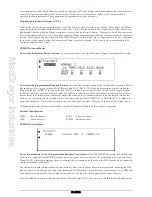
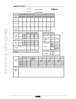
Please note that the channel names shown will depend on the selections made in System Mode - Wing TYPE.
To set a travel value,
highlight the required figure by rotating the Scroll Bar and click on it to bring up the sub menu. Pairs
of figures are surrounded by a box to indicate that they are selected. Move the control stick to swap between the right/left,
up/down figures and rotate the Scroll Bar to alter the setting. To return the figures to the default of 100%, press the clear
(CLR) key at the left hand side of the screen. When the required setting is achieved, click the Scroll Bar to exit the sub
menu.
Press the LIST key to return to the Function Menu. Press the enter (ENT) key to return to the Information Display Screen.
Elevator to Flap Mix
The Function Menu List is accessed from the Information Display Screen by pressing the LIST key. From the Function
Menu List, rotate the Scroll Bar to highlight the "ELE->FLP M" menu choice and click the Scroll Bar
.
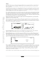
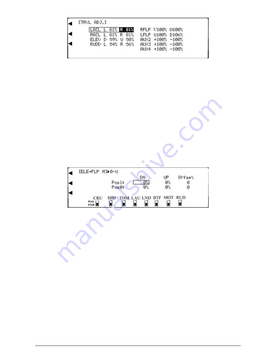
The Elevator to Flap mix moves the Flaps in addition to the Elevator to give more pitch authority.
Two different Elevator to Flap settings may be chosen with an offset and independent up or down travel adjustment. The
required mix can be selected with the Flight Modes or with various switches. Mix values between
±
125% may be set and
negative values reverse the Flap movement direction. The offset is the neutral Flap position when the mix is active.
Please note that the display will only show the Flight Modes switches activated in System Mode - DeviceSEL.
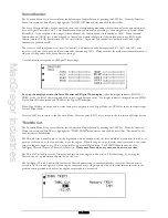
To set a mix value and offset,
highlight the required figure by rotating the Scroll Bar and click on it to bring up the sub
menu. The figure is surrounded by a box to indicate that it is selected. Rotate the Scroll Bar to alter the setting. To return
the figures to the default of 0, press the clear (CLR) key at the left hand side of the screen. When the required setting is
achieved, click the Scroll Bar to exit the sub menu.
If the mix is to be permanently on, only the figures set for position 0 (POS0) will be used. Any settings for position 1
(POS1) will be ignored.
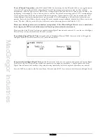
To select an activation switch,
highlight the required switch by rotating the Scroll Bar and click on it to toggle between
position "0" and position "1". The black indicator square moves between the bottom of the box (POS0) and the top of the
box (POS1) to indicate the selection. To return the sub menu selection to the default of position 0 (POS0), press the clear
(CLR) key at the left hand side of the screen. When the required setting is achieved, click the Scroll Bar to exit the sub
menu. If required, more than one switch may be used to activate the mix and with multiple switches selected, any switch in
the "1" position will cause the "Pos1:" values to be used.
Note that when a switch/Flight Mode is selected to change between the mix values, the switch indicator to the right of
[ELE->FLP M] on the top left of the screen changes from "0" ("Pos0:" value) to "1" ("Pos1:" value) as the activation switch
is moved. The direction indicator changes form U (Elevator up) to D (Elevator down) as the Elevator stick is moved.
Press the LIST key to return to the Function Menu. Press the enter (ENT) key to return to the Information Display Screen.
Summary of Contents for PCM9XII
Page 1: ...MacGregor Industries MACGREGOR INDUSTRIES Instruction Manual PCM9XII ...
Page 4: ...MacGregor Industries This page is intentionally blank ...
Page 43: ...MacGregor Industries 39 HELI ...
Page 65: ...MacGregor Industries 61 AERO ...
Page 85: ...MacGregor Industries 81 GLIDER ...
Page 86: ...MacGregor Industries This page is intentionally blank ...
Page 87: ...MacGregor Industries This page is intentionally blank ...


