MacGregor Industries
51 AERO
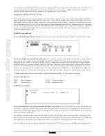
To set a Throttle stick activation point,
highlight the THRO STK menu choice by rotating the Scroll Bar and click on it
to bring up the sub menu. The words are surrounded by a box to indicate that they are selected. Rotate the Scroll Bar to
alter the setting. Figures between INH (inhibited or zero) and 100 may be set with zero corresponding to Throttle low and
100 corresponding to full Throttle. To return the figures to the default of INH (inhibited or 0), press the clear (CLR) key at
the left hand side of the screen. When the required setting is achieved, click the Scroll Bar to exit the sub menu. The servo
speed will change from the POS1 values when the Throttle stick is below the setting point to the POS0 values when it is
above the setting point.
Press the LIST key to return to the Function Menu. Press the enter (ENT) key to return to the Information Display Screen.
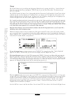
Multipoint Program Mixes 1 and 2.
The Function Menu List is accessed from the Information Display Screen by pressing the LIST key. From the Function
Menu List, rotate the Scroll Bar to highlight the "PROG.Mix" menu choice and click the Scroll Bar. The default is for the
mixes to be inhibited.
Programmable mixes enable any channel to be mixed to any channel (including itself!). When a channel is mixed with itself,
a positive mix value increases the effective servo movement while a negative mix value decreases the effective movement.
Where two servos are used to perform a particular function, the mix can be to the function rather than to an individual
servo. Mix values between
±
100% can be set for each of the 7 setting points (0 to 6) and the transition between the setting
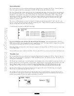
points can be linear or smoothed with the exponential feature. A graphical representation of the resultant mix response is
displayed on the screen with a vertical cursor indicating the position of the Master channel.
The mix can be permanently active, or enabled and disabled by the Flight Modes and other switches, or by a pre-selected
Throttle stick position. When the mix is activated by a switch or Throttle stick position, the Pos1 values always take priority
over the Pos0 values. If multiple switches are selected and one of the switches is in the POS1 position, then all other
switches are ignored and the Pos1 values are used.
The channel providing the signal for the mix is known as the Master (Mast) channel and the channel being controlled is the
Slave (Slav) channel. When using the Throttle channel as the Master, any trim input is automatically passed to the Slave.
With all other channels, Master input channel trim movements are ignored.
Master channel modifiers (Travel Adjustments, Dual Rates etc.) are automatically passed to the Slave channel. As an
example, if the Master channel travel is reduced by 50% by the Dual Rate feature, the Slave now only moves by 50%. The
four primary channels have an additional special Master mix - the Origin mix (# mix), where all modifiers are ignored and
the Slave always moves by the same amount.
The default mix, with the graph line running from bottom left to top right, gives a linear response with the Slave channel
exactly replicating the Master channel over the entire Master input range. A straight graph line running from top left to
bottom right would give a Slave channel response exactly replicating the Master input - but in reverse. If all mix points are
set to zero, the graph shows a horizontal line in the centre of the screen. (Wherever the Master channel moves, the Slave
stays at the centre - the mix is effectively inhibited.)
Input and output monitor figures are displayed at the bottom left of the screen. The IN figure represents the Master (input)
channel position with zero being at one extreme, 50 being the centre and 100 being the other extreme. The OUT figure
represents the Slave (output) channel position with -100 being at one extreme, zero being the centre and +100 being the
other extreme. With a linear response, the figures move together and with a curved response, the output follows the non-
linear curve.
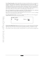
Please note that the actual Master and Slave channel selection displayed will depend on the settings made in
System Mode - DeviceSEL and System Mode - Wing TYPE.
Master Channel Identification.
THRO
Throttle channel.
#AIL
Aileron stick Origin Mix.
AILE
Aileron channel.
#ELE Elevator stick Origin Mix.
ELEV
Elevator channel.
#RUD Rudder stick Origin Mix.
RUDD Rudder channel.
LTRM Left hand Digital Trim.
FLAP
Flap channel.
LLVR
Left hand side cheek lever.
AUX2
Auxiliary 2 channel.
RTRM Right hand Digital Trim.
AUX3
Auxiliary 3 channel.
RLVR
Right hand side cheek lever.
AUX4
Auxiliary 4 channel.
SNPT
Snap roll bias switch. (Input toggles between
±
100%.)
#THR
Throttle stick Origin Mix.
Summary of Contents for PCM9XII
Page 1: ...MacGregor Industries MACGREGOR INDUSTRIES Instruction Manual PCM9XII ...
Page 4: ...MacGregor Industries This page is intentionally blank ...
Page 43: ...MacGregor Industries 39 HELI ...
Page 65: ...MacGregor Industries 61 AERO ...
Page 85: ...MacGregor Industries 81 GLIDER ...
Page 86: ...MacGregor Industries This page is intentionally blank ...
Page 87: ...MacGregor Industries This page is intentionally blank ...


