MacGregor Industries
64 GLIDER
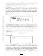
To change the channel movement direction,
highlight the required channel by rotating the Scroll Bar and click on it to
toggle between normal and reversed. The black direction indicator square moves between the top of the box (reversed) and
the bottom of the box (normal) to indicate the current selection. When the required setting is achieved, click the Scroll Bar
to exit the sub menu.
Press the LIST key to return to the Function Menu. Press the enter (ENT) key to return to the Information Display Screen.
Sub Trim
The Function Menu List is accessed from the Information Display Screen by pressing the LIST key. From the Function
Menu List, rotate the Scroll Bar to highlight the "Sub Trim" menu choice and click the Scroll Bar.
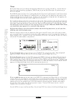
The Sub Trim feature can be used to dial out small inaccuracies in the servo or transmitter settings and so modify the
neutral position of a servo so that the arm is exactly at right angles to the direction of movement. It is usually best to
position the arm as close as possible to the correct position and use only a small value of sub trim. As servo movement has
a maximum of 150%, large sub trim values will restrict the amount of movement on the sub trimmed side of neutral.
Sub trim values of between
±
250 (or left/right/up/down 250) can be set corresponding to about 70% of servo travel.
Please note that the channel names shown will depend on the selections made in System Mode - Wing TYPE.
To change the sub trim value,
highlight the required channel by rotating the Scroll Bar and click on it to bring up the sub
menu. The highlighting is surrounded by a box to indicate that it is selected. Rotate the Scroll Bar to alter the setting. To
return the figures to the default of zero, press the clear (CLR) key at the left hand side of the screen. When the required
setting is achieved, click the Scroll Bar to exit the sub menu.
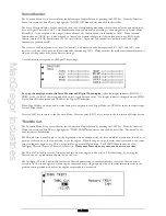
Channel Identification:
LAIL
Left Aileron - receiver channel 1, marked THRO on receiver case.
RAIL
Right Aileron - receiver channel 2, marked AILE on receiver case.
ELEV
Elevator - receiver channel 3, marked ELEV on receiver case.
RUDD Rudder - receiver channel 4, marked RUDD on receiver case.
MOTO Channel for motor control - receiver channel 5, marked GEAR on receiver case. Note that if dual Flaps are
selected in System Mode - Wing TYPE, this channel will be marked RFLP (right Flap).
FLAP
Flap channel - receiver channel 6, marked AUX1 or FLAP on receiver case. Note that if dual Flaps are selected
in System Mode - Wing TYPE, this channel will be marked LFLP (left Flap).
AUX2
Auxiliary Channel 2 - receiver channel 7, marked AUX2 on receiver case.
AUX3
Auxiliary Channel 3 - receiver channel 8, marked AUX3 on receiver case.
AUX4
Auxiliary Channel 4 - receiver channel 9, marked AUX4 on receiver case.
Press the LIST key to return to the Function Menu. Press the enter (ENT) key to return to the Information Display Screen.
Travel Adjust
The Function Menu List is accessed from the Information Display Screen by pressing the LIST key. From the Function
Menu List, rotate the Scroll Bar to highlight the "TRVL ADJ." menu choice and click the Scroll Bar.
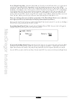
Travel Adjust, (Endpoint Adjustment/Travel Volume), sets the movement of the servo arm. The travel adjust range is from
zero to 150% with individual adjustment in each direction of servo travel. The adjustment is for the individual servo and
when two servos are controlled from a single stick (Ailerons say), the Dual Rate function should be used to set the
movement, so that the travel of both servos is adjusted together.
Summary of Contents for PCM9XII
Page 1: ...MacGregor Industries MACGREGOR INDUSTRIES Instruction Manual PCM9XII ...
Page 4: ...MacGregor Industries This page is intentionally blank ...
Page 43: ...MacGregor Industries 39 HELI ...
Page 65: ...MacGregor Industries 61 AERO ...
Page 85: ...MacGregor Industries 81 GLIDER ...
Page 86: ...MacGregor Industries This page is intentionally blank ...
Page 87: ...MacGregor Industries This page is intentionally blank ...


