SECTION 3 - CHASSIS & TURNTABLE
3121234
3-99
Assembly
Replace all seals and seal rings with new ones each time you
reassemble the Torqlink™ unit. Lubricate all seals and seal rings
with SAE 10W40 oil or clean grease before assembly.
NOTE:
Individual seals and seal rings as well as a complete seal kit
are available. The parts should be available through most
OEM parts distributors or Parker approved Torqlink™ dis-
tributors. (Contact your local dealer for availability).
NOTE:
Unless otherwise indicated, do not oil or grease parts
before assembly.
Wash all parts in clean petroleum-based solvents before
assembly. Blow them dry with compressed air. Remove any
paint chips from mating surfaces of the end cover, commuta-
tor set, manifold rotor set, wear plate and housing and from
port and sealing areas.
SINCE THEY ARE FLAMMABLE, BE EXTREMELY CAREFUL WHEN USING ANY
SOLVENT. EVEN A SMALL EXPLOSION OR FIRE COULD CAUSE INJURY OR
DEATH.
WEAR EYE PROTECTION AND BE SURE TO COMPLY WITH OSHA OR OTHER MAX-
IMUM AIR PRESSURE REQUIREMENTS.
1.
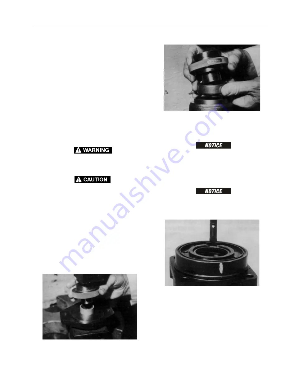
If the housing (18) bearing components were removed
for replacement, thoroughly coat and pack a new outer
bearing/bushing (19) with clean corrosion resistant
grease recommended in the material section. Press the
new bearing/bushing into the counterbore at the
mounting flange end of the housing, using the appro-
priate sized bearing mandrel, which will control the
bearing/ bushing depth.
Torqlink™ housings require the use of bearing mandrel
to press bearing/ bushing (19) into the housing to a
required depth of 0.151/0.161 in. (3.84/4.09 mm) from
the end of the bearing counterbore.
NOTE:
Bearing mandrel must be pressed against the lettered end
of bearing shell. Take care that the housing bore is square
with the press base and the bearing/bushing is not cocked
when pressing a bearing/bushing into the housing.
IF THE BEARING MANDREL SPECIFIED IN THE “ TOOLS AND MATERIALS
REQUIRED FOR SERVICING” SECTION IS NOT AVAILABLE AND ALTERNATE
METHODS ARE USED TO PRESS IN BEARING/BUSHING (13) AND (19) THE
BEARING/BUSHING DEPTHS SPECIFIED MUST BE ACHIEVED TO INSURE ADE-
QUATE BEARING SUPPORT AND CORRECT RELATIONSHIP TO ADJACENT COM-
PONENTS WHEN ASSEMBLED.
BECAUSE THE BEARING/BUSHINGS (13) AND (19) HAVE A PRESS FIT INTO THE
HOUSING THEY MUST BE DISCARDED WHEN REMOVED. THEY MUST NOT BE
REUSED.
Summary of Contents for 680S
Page 2: ......
Page 52: ...SECTION 2 GENERAL 2 14 3121234 NOTES...
Page 55: ...SECTION 3 CHASSIS TURNTABLE 3121234 3 3 This page left blank intentionally...
Page 89: ...SECTION 3 CHASSIS TURNTABLE 3121234 3 37 Figure 3 28 Assembly Tools Seal Pressing...
Page 139: ...SECTION 3 CHASSIS TURNTABLE 3121234 3 87 Figure 3 62 Swing Hub Prior to SN 0300134352...
Page 143: ...SECTION 3 CHASSIS TURNTABLE 3121234 3 91 Figure 3 64 Swing Brake...
Page 205: ...SECTION 3 CHASSIS TURNTABLE 3121234 3 153 This page left blank intentionally...
Page 208: ...SECTION 3 CHASSIS TURNTABLE 3 156 3121234 Figure 3 91 Generator Electrical Circuit Diagram...
Page 224: ...SECTION 3 CHASSIS TURNTABLE 3 172 3121234 Figure 3 103 EMR 2 Engine Side Equipment...
Page 225: ...SECTION 3 CHASSIS TURNTABLE 3121234 3 173 Figure 3 104 Deutz EMR 2 Troubleshooting Flow Chart...
Page 229: ...SECTION 3 CHASSIS TURNTABLE 3121234 3 177 Figure 3 108 EMR 2 Engine Plug Pin Identification...
Page 230: ...SECTION 3 CHASSIS TURNTABLE 3 178 3121234 Figure 3 109 EMR 2 Vehicle Plug Pin Identification...
Page 231: ...SECTION 3 CHASSIS TURNTABLE 3121234 3 179 Figure 3 110 EMR2 Fault Codes Sheet 1 of 5...
Page 232: ...SECTION 3 CHASSIS TURNTABLE 3 180 3121234 Figure 3 111 EMR2 Fault Codes Sheet 2 of 5...
Page 233: ...SECTION 3 CHASSIS TURNTABLE 3121234 3 181 Figure 3 112 EMR2 Fault Codes Sheet 3 of 5...
Page 234: ...SECTION 3 CHASSIS TURNTABLE 3 182 3121234 Figure 3 113 EMR2 Fault Codes Sheet 4 of 5...
Page 235: ...SECTION 3 CHASSIS TURNTABLE 3121234 3 183 Figure 3 114 EMR2 Fault Codes Sheet 5 of 5...
Page 264: ...SECTION 3 CHASSIS TURNTABLE 3 212 3121234 NOTES...
Page 285: ...SECTION 4 BOOM PLATFORM 3121234 4 21 This page left blank intentionally...
Page 333: ...SECTION 4 BOOM PLATFORM 3121234 4 69 Figure 4 25 Load Sensing Device...
Page 336: ...SECTION 4 BOOM PLATFORM 4 72 3121234 NOTES...
Page 416: ...SECTION 5 BASIC HYDRAULICS INFORMATION SCHEMATICS 5 80 3121234 NOTES...
Page 423: ...SECTION 6 JLG CONTROL SYSTEM 3121234 6 7 Figure 6 2 ADE Block Diagram...
Page 480: ...SECTION 6 JLG CONTROL SYSTEM 6 64 3121234 NOTES...
Page 528: ...SECTION 7 BASIC ELECTRICAL INFORMATION SCHEMATICS 7 48 3121234 NOTES...
Page 529: ......


