SECTION 4 - BOOM & PLATFORM
3121234
4-65
Greasing Thrust Washers
5.
After the actuator is assembled but before it is put into
service, the thrust washer area must be packed with
Lithium grease.
6.
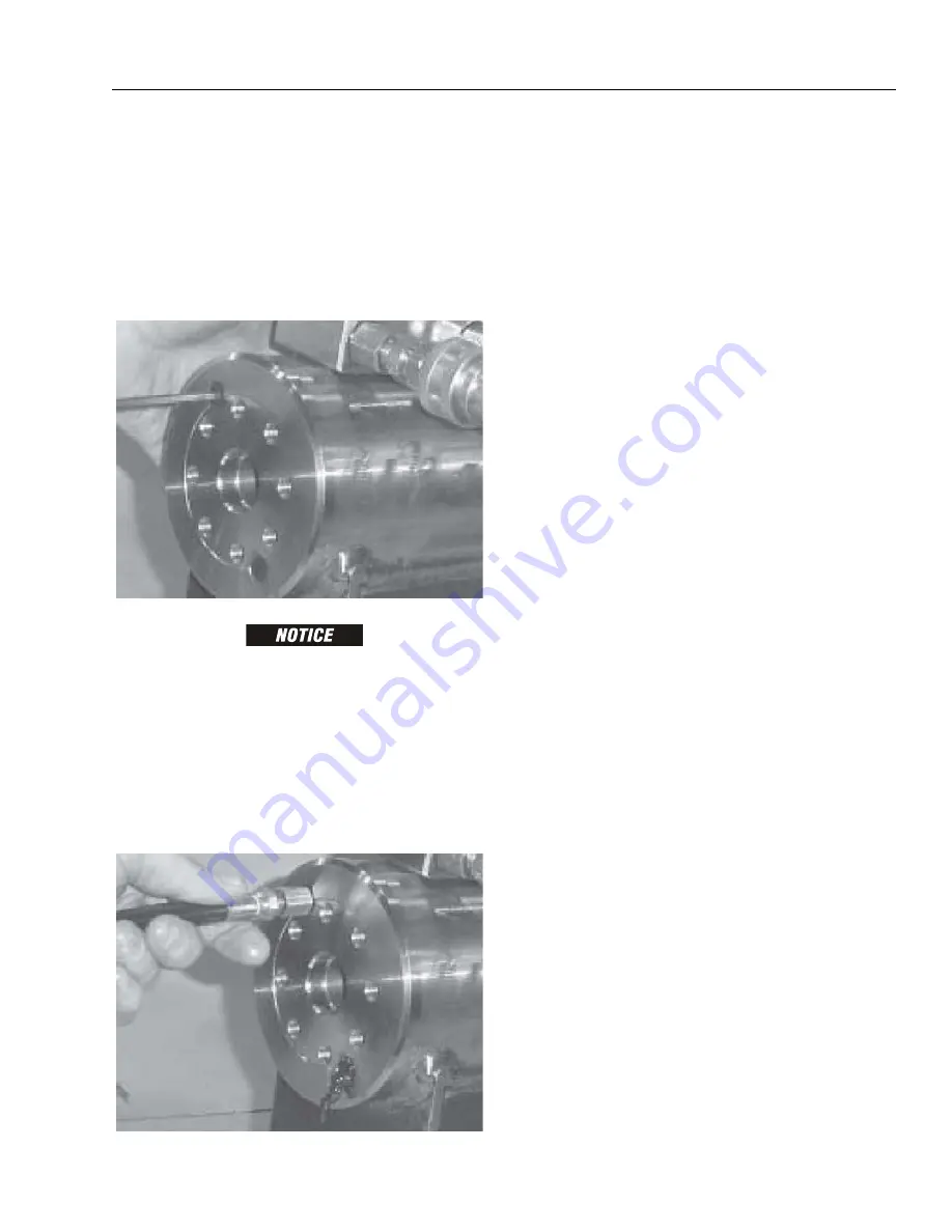
There are two grease ports located on both the shaft
flange and the end cap. They are plugged with cap-
screws (6) or set screws. Remove the grease port screws
from the shaft flange and end cap. (See exploded view)
IF A HYDRAULIC TEST BENCH IS NOT AVAILABLE, THE ACTUATOR CAN BE
ROTATED BY HAND, OPEN THE PRESSURE PORTS AND USE A PRY BAR WITH
CAPSCREWS INSERTED INTO THE SHAFT FLANGE TO TURN THE SHAFT IN THE
DESIRED DIRECTION.
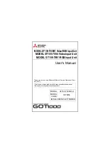
7.
Insert the tip of a grease gun into one port and apply
grease to the shaft flange. Continue applying until
grease flows from the opposite port. Cycle the actuator
five times and apply grease again. Repeat this process
on the end cap. Insert the capscrews into the grease
ports and tighten to 25 in. lbs. (2.8 Nm).
Testing the Actuator
If the equipment is available, the actuator should be tested on a
hydraulic test bench. The breakaway pressure — the pressure at
which the shaft begins to rotate — should be approximately
400 psi (28 bar). Cycle the actuator at least 25 times at 3000 psi
(207 bar) pressure. After the 25 rotations, increase the pressure to
4500 psi (315 bar) to check for leaks and cracks. Perform the test
again at the end of the rotation in the opposite direction.
Testing the Actuator for Internal Leakage
If the actuator is equipped with a counterbalance valve, plug the
valve ports. Connect the hydraulic lines to the housing ports.
Bleed all air from the actuator (see Installation and Bleeding)
Rotate the shaft to the end of rotation at 3000 psi (207 bar) and
maintain pressure. Remove the hydraulic line from the non-pres-
surized side.
Continuous oil flow from the open housing port indicates inter-
nal leakage across the piston. Replace the line and rotate the
shaft to the end of rotation in the opposite direction. Repeat the
test procedure outlined above for the other port. If there is an
internal leak, disassemble, inspect and repair.
Summary of Contents for 680S
Page 2: ......
Page 52: ...SECTION 2 GENERAL 2 14 3121234 NOTES...
Page 55: ...SECTION 3 CHASSIS TURNTABLE 3121234 3 3 This page left blank intentionally...
Page 89: ...SECTION 3 CHASSIS TURNTABLE 3121234 3 37 Figure 3 28 Assembly Tools Seal Pressing...
Page 139: ...SECTION 3 CHASSIS TURNTABLE 3121234 3 87 Figure 3 62 Swing Hub Prior to SN 0300134352...
Page 143: ...SECTION 3 CHASSIS TURNTABLE 3121234 3 91 Figure 3 64 Swing Brake...
Page 205: ...SECTION 3 CHASSIS TURNTABLE 3121234 3 153 This page left blank intentionally...
Page 208: ...SECTION 3 CHASSIS TURNTABLE 3 156 3121234 Figure 3 91 Generator Electrical Circuit Diagram...
Page 224: ...SECTION 3 CHASSIS TURNTABLE 3 172 3121234 Figure 3 103 EMR 2 Engine Side Equipment...
Page 225: ...SECTION 3 CHASSIS TURNTABLE 3121234 3 173 Figure 3 104 Deutz EMR 2 Troubleshooting Flow Chart...
Page 229: ...SECTION 3 CHASSIS TURNTABLE 3121234 3 177 Figure 3 108 EMR 2 Engine Plug Pin Identification...
Page 230: ...SECTION 3 CHASSIS TURNTABLE 3 178 3121234 Figure 3 109 EMR 2 Vehicle Plug Pin Identification...
Page 231: ...SECTION 3 CHASSIS TURNTABLE 3121234 3 179 Figure 3 110 EMR2 Fault Codes Sheet 1 of 5...
Page 232: ...SECTION 3 CHASSIS TURNTABLE 3 180 3121234 Figure 3 111 EMR2 Fault Codes Sheet 2 of 5...
Page 233: ...SECTION 3 CHASSIS TURNTABLE 3121234 3 181 Figure 3 112 EMR2 Fault Codes Sheet 3 of 5...
Page 234: ...SECTION 3 CHASSIS TURNTABLE 3 182 3121234 Figure 3 113 EMR2 Fault Codes Sheet 4 of 5...
Page 235: ...SECTION 3 CHASSIS TURNTABLE 3121234 3 183 Figure 3 114 EMR2 Fault Codes Sheet 5 of 5...
Page 264: ...SECTION 3 CHASSIS TURNTABLE 3 212 3121234 NOTES...
Page 285: ...SECTION 4 BOOM PLATFORM 3121234 4 21 This page left blank intentionally...
Page 333: ...SECTION 4 BOOM PLATFORM 3121234 4 69 Figure 4 25 Load Sensing Device...
Page 336: ...SECTION 4 BOOM PLATFORM 4 72 3121234 NOTES...
Page 416: ...SECTION 5 BASIC HYDRAULICS INFORMATION SCHEMATICS 5 80 3121234 NOTES...
Page 423: ...SECTION 6 JLG CONTROL SYSTEM 3121234 6 7 Figure 6 2 ADE Block Diagram...
Page 480: ...SECTION 6 JLG CONTROL SYSTEM 6 64 3121234 NOTES...
Page 528: ...SECTION 7 BASIC ELECTRICAL INFORMATION SCHEMATICS 7 48 3121234 NOTES...
Page 529: ......


