SECTION 4 - BOOM & PLATFORM
3121234
4-37
5.
Connect the hydraulic lines to the cylinder as tagged
during removal.
6.
Remove the supporting device and function check the
boom to make sure the lift cylinder operates properly
and there are no leaks.
4.8
WIRE ROPE
Each day before using the machine:
1.
Raise the main boom to approximately horizontal.
2.
Extend and retract the boom sections.
3.
Check for delayed movement of the fly section, which
indicates loose wire ropes.
Inspection
NOTE:
The pictures in this paragraph are just samples to show the
replacement criteria of the rope.
1.
Inspect ropes for broken wires, particularly valley wire
breaks and breaks at end terminations.
2.
Inspect ropes for corrosion.
3.
Inspect ropes for kinks or abuse.
4.
Inspect sheaves for condition of bearings/pins. (See
Dimension Of Sheaves for proper dimension.)
5.
Inspect sheaves for condition of flanges. (See Dimension
Of Sheaves for proper dimension.)
6.
Inspect sheaves with a groove wearout gauge for exces-
sive wear.
7.
Ropes passing inspection should be lubricated with wire
rope lubricant before reassembly.
Three Month Inspection
1.
Remove boom covers and visually (with flashlight)
inspect the ropes for rust, broken wires, frays, abuse, or
any signs of abnormalities.
2.
Check rope tension by deflecting the ropes by hand.
Properly tensioned ropes should have little or no move-
ment.
12 Year or 7000 Hour Replacement
Mandatory wire rope and sheave replacement.
Additional inspection required if:
1.
Machine is exposed to hostile environment or condi-
tions.
2.
Erratic boom operation or unusual noise exists.
3.
Machine is idle for an extended period.
4.
Boom is overloaded or sustained a shock load.
5.
Boom exposed to electrical arc. Wires may be fused
internally.
Replacement Criteria
1.
Sheaves and wire rope must be replaced as sets.
2.
Rusted or corroded wire ropes.
3.
Kinked, “bird caged”, or crushed ropes.
4.
Ropes at end of adjustment range.
5.
Sheaves failing wearout gage inspection.
6.
Ropes with 6 total broken wires in one rope lay, 3 in one
strand in one rope lay, 1 valley break, or 1 break at any
end termination.
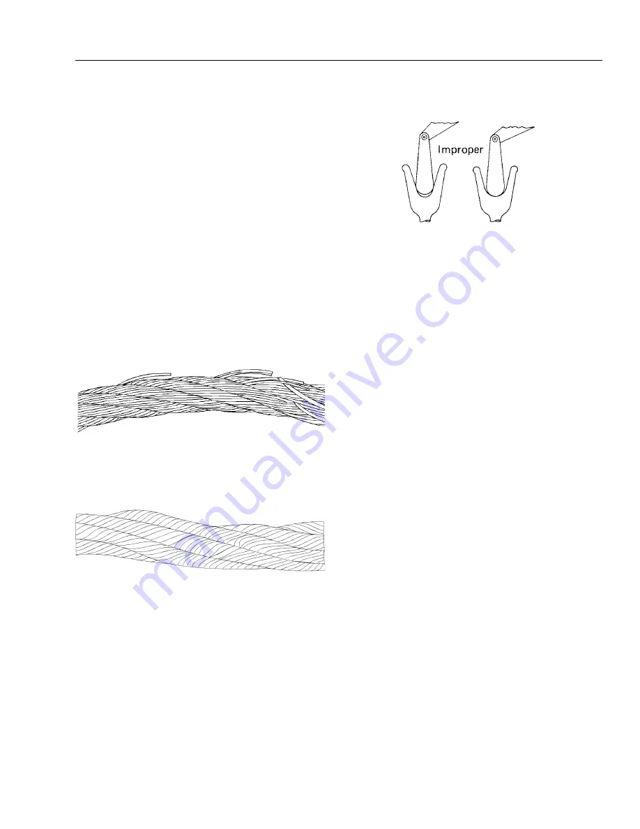
Flexing a wire rope can often expose broken wires hidden in
valleys between strands.
A kink is caused by pulling down a loop
in a slack line during improper handling,
installation, or operation.
Observe the groove so that it may be clearly seen whether the
contour of the gauge matches the
contour of the bottom of the groove.
Summary of Contents for 680S
Page 2: ......
Page 52: ...SECTION 2 GENERAL 2 14 3121234 NOTES...
Page 55: ...SECTION 3 CHASSIS TURNTABLE 3121234 3 3 This page left blank intentionally...
Page 89: ...SECTION 3 CHASSIS TURNTABLE 3121234 3 37 Figure 3 28 Assembly Tools Seal Pressing...
Page 139: ...SECTION 3 CHASSIS TURNTABLE 3121234 3 87 Figure 3 62 Swing Hub Prior to SN 0300134352...
Page 143: ...SECTION 3 CHASSIS TURNTABLE 3121234 3 91 Figure 3 64 Swing Brake...
Page 205: ...SECTION 3 CHASSIS TURNTABLE 3121234 3 153 This page left blank intentionally...
Page 208: ...SECTION 3 CHASSIS TURNTABLE 3 156 3121234 Figure 3 91 Generator Electrical Circuit Diagram...
Page 224: ...SECTION 3 CHASSIS TURNTABLE 3 172 3121234 Figure 3 103 EMR 2 Engine Side Equipment...
Page 225: ...SECTION 3 CHASSIS TURNTABLE 3121234 3 173 Figure 3 104 Deutz EMR 2 Troubleshooting Flow Chart...
Page 229: ...SECTION 3 CHASSIS TURNTABLE 3121234 3 177 Figure 3 108 EMR 2 Engine Plug Pin Identification...
Page 230: ...SECTION 3 CHASSIS TURNTABLE 3 178 3121234 Figure 3 109 EMR 2 Vehicle Plug Pin Identification...
Page 231: ...SECTION 3 CHASSIS TURNTABLE 3121234 3 179 Figure 3 110 EMR2 Fault Codes Sheet 1 of 5...
Page 232: ...SECTION 3 CHASSIS TURNTABLE 3 180 3121234 Figure 3 111 EMR2 Fault Codes Sheet 2 of 5...
Page 233: ...SECTION 3 CHASSIS TURNTABLE 3121234 3 181 Figure 3 112 EMR2 Fault Codes Sheet 3 of 5...
Page 234: ...SECTION 3 CHASSIS TURNTABLE 3 182 3121234 Figure 3 113 EMR2 Fault Codes Sheet 4 of 5...
Page 235: ...SECTION 3 CHASSIS TURNTABLE 3121234 3 183 Figure 3 114 EMR2 Fault Codes Sheet 5 of 5...
Page 264: ...SECTION 3 CHASSIS TURNTABLE 3 212 3121234 NOTES...
Page 285: ...SECTION 4 BOOM PLATFORM 3121234 4 21 This page left blank intentionally...
Page 333: ...SECTION 4 BOOM PLATFORM 3121234 4 69 Figure 4 25 Load Sensing Device...
Page 336: ...SECTION 4 BOOM PLATFORM 4 72 3121234 NOTES...
Page 416: ...SECTION 5 BASIC HYDRAULICS INFORMATION SCHEMATICS 5 80 3121234 NOTES...
Page 423: ...SECTION 6 JLG CONTROL SYSTEM 3121234 6 7 Figure 6 2 ADE Block Diagram...
Page 480: ...SECTION 6 JLG CONTROL SYSTEM 6 64 3121234 NOTES...
Page 528: ...SECTION 7 BASIC ELECTRICAL INFORMATION SCHEMATICS 7 48 3121234 NOTES...
Page 529: ......


