SECTION 4 - BOOM & PLATFORM
4-18
3121234
4.5
BOOM CLEANLINESS GUIDELINES
The following are guidelines for internal boom cleanliness for
machines that are used in excessively dirty environments.
1.
JLG recommends the use of the JLG Hostile Environment
Package if available to keep the internal portions of a
boom cleaner and to help prevent dirt and debris from
entering the boom. This package reduces the amount of
contamination which can enter the boom but does not
eliminate the need for more frequent inspections and
maintenance when used in these types of environ-
ments.
2.
JLG recommends to follow all guidelines for servicing
the equipment in accordance with the instructions out-
lined in the JLG Service & Maintenance Manual for the
machine. Periodic maintenance and inspection is vital to
the proper operation of the machine. The frequency of
service and maintenance must be increased as environ-
ment, severity, and frequency of usage requires.
3.
Debris and foreign matter inside of the boom can cause
premature failure of components and should be
removed. Methods to remove debris should always be
done using all applicable safety precautions outlined in
the JLG Service & Maintenance Manuals.
4.
The first attempt to remove debris from inside the boom
must be to utilize pressurized air to blow the debris
toward the nearest exiting point from the boom. Make
sure that all debris is removed before operating the
machine.
5.
If pressurized air cannot dislodge the debris, then water
with mild solvents applied via a pressure washer can be
used. Again the method is to wash the debris toward the
nearest exiting point from the boom. Make sure that all
debris is removed, that no “puddling” of water has
occurred, and that the boom internal components are
dry prior to operating the machine. Make sure to comply
with all federal and local laws for disposing of the wash
water and debris.
6.
If neither pressurized air nor washing of the boom dis-
lodges and removes the debris, then disassemble the
boom in accordance to the instructions outlined in the
JLG Service & Maintenance Manual to remove the
debris.
4.6
MAIN BOOM ASSEMBLY
Removal
1.
Using suitable lifting equipment, adequately support
boom assembly weight along entire length.
HYDRAULIC LINES AND PORTS SHOULD BE CAPPED IMMEDIATELY AFTER DIS-
CONNECTING LINES TO AVOID ENTRY OF CONTAMINANTS INTO SYSTEM.
2.
Tag and disconnect hydraulic lines from telescope cylin-
der. Use a suitable container to retain any residual
hydraulic fluid. Cap hydraulic lines and ports.
3.
Use an adequate support for the main boom lift cylin-
der. Extend main boom cylinder with auxiliary power
switch to gain access to remove rod end pin.
NOTE:
The main boom lift cylinder weighs approximately 615 lbs.
(279 kg).
4.
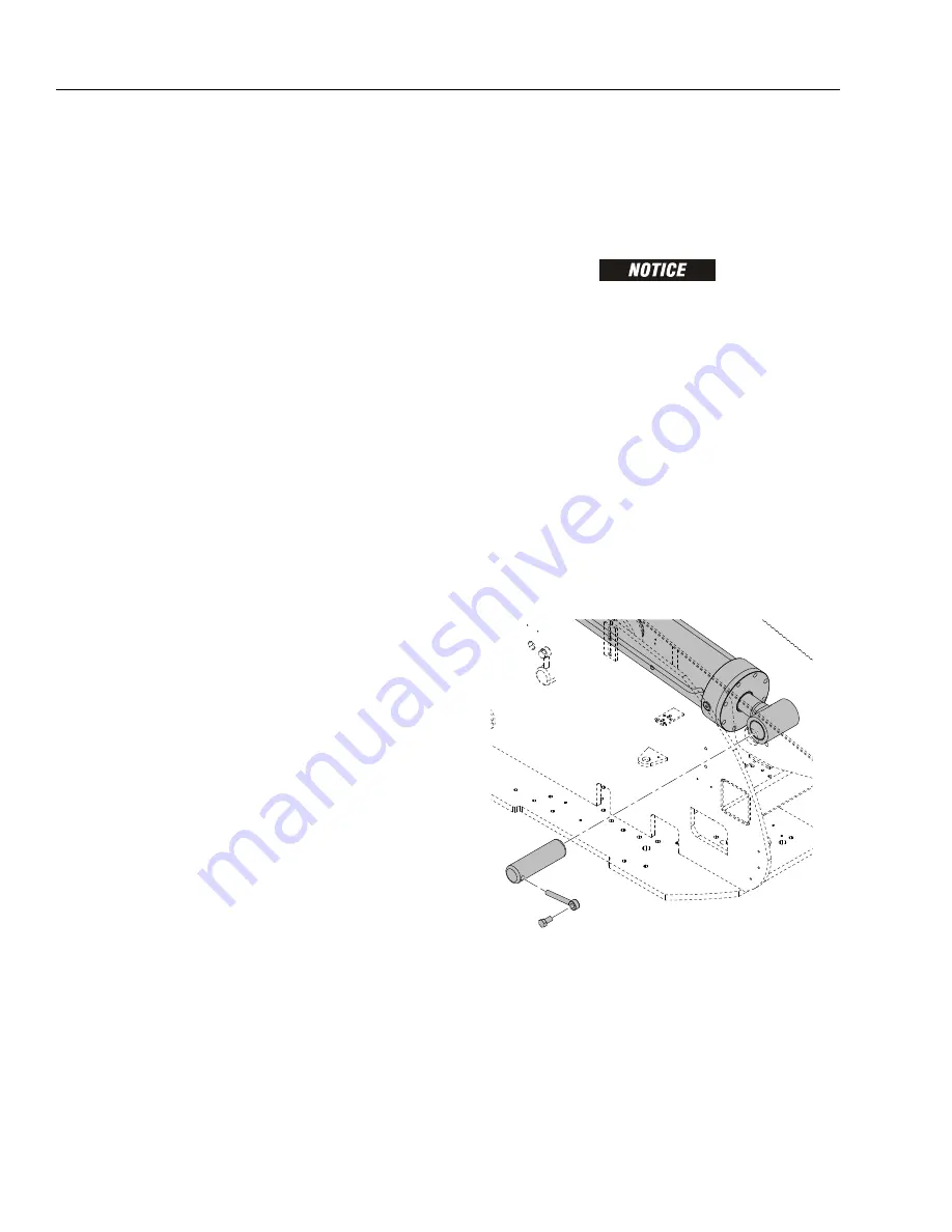
Using a suitable brass drift and hammer, remove hard-
ware securing the main boom lift cylinder rod end pin to
the base boom section. Remove the main boom lift cyl-
inder pin from base boom. Retract the main boom lift
cylinder by using the auxiliary power switch.
5.
Using an adequate supporting device, support the tim-
ing link so it doesn’t fall when the pin is removed.
Summary of Contents for 680S
Page 2: ......
Page 52: ...SECTION 2 GENERAL 2 14 3121234 NOTES...
Page 55: ...SECTION 3 CHASSIS TURNTABLE 3121234 3 3 This page left blank intentionally...
Page 89: ...SECTION 3 CHASSIS TURNTABLE 3121234 3 37 Figure 3 28 Assembly Tools Seal Pressing...
Page 139: ...SECTION 3 CHASSIS TURNTABLE 3121234 3 87 Figure 3 62 Swing Hub Prior to SN 0300134352...
Page 143: ...SECTION 3 CHASSIS TURNTABLE 3121234 3 91 Figure 3 64 Swing Brake...
Page 205: ...SECTION 3 CHASSIS TURNTABLE 3121234 3 153 This page left blank intentionally...
Page 208: ...SECTION 3 CHASSIS TURNTABLE 3 156 3121234 Figure 3 91 Generator Electrical Circuit Diagram...
Page 224: ...SECTION 3 CHASSIS TURNTABLE 3 172 3121234 Figure 3 103 EMR 2 Engine Side Equipment...
Page 225: ...SECTION 3 CHASSIS TURNTABLE 3121234 3 173 Figure 3 104 Deutz EMR 2 Troubleshooting Flow Chart...
Page 229: ...SECTION 3 CHASSIS TURNTABLE 3121234 3 177 Figure 3 108 EMR 2 Engine Plug Pin Identification...
Page 230: ...SECTION 3 CHASSIS TURNTABLE 3 178 3121234 Figure 3 109 EMR 2 Vehicle Plug Pin Identification...
Page 231: ...SECTION 3 CHASSIS TURNTABLE 3121234 3 179 Figure 3 110 EMR2 Fault Codes Sheet 1 of 5...
Page 232: ...SECTION 3 CHASSIS TURNTABLE 3 180 3121234 Figure 3 111 EMR2 Fault Codes Sheet 2 of 5...
Page 233: ...SECTION 3 CHASSIS TURNTABLE 3121234 3 181 Figure 3 112 EMR2 Fault Codes Sheet 3 of 5...
Page 234: ...SECTION 3 CHASSIS TURNTABLE 3 182 3121234 Figure 3 113 EMR2 Fault Codes Sheet 4 of 5...
Page 235: ...SECTION 3 CHASSIS TURNTABLE 3121234 3 183 Figure 3 114 EMR2 Fault Codes Sheet 5 of 5...
Page 264: ...SECTION 3 CHASSIS TURNTABLE 3 212 3121234 NOTES...
Page 285: ...SECTION 4 BOOM PLATFORM 3121234 4 21 This page left blank intentionally...
Page 333: ...SECTION 4 BOOM PLATFORM 3121234 4 69 Figure 4 25 Load Sensing Device...
Page 336: ...SECTION 4 BOOM PLATFORM 4 72 3121234 NOTES...
Page 416: ...SECTION 5 BASIC HYDRAULICS INFORMATION SCHEMATICS 5 80 3121234 NOTES...
Page 423: ...SECTION 6 JLG CONTROL SYSTEM 3121234 6 7 Figure 6 2 ADE Block Diagram...
Page 480: ...SECTION 6 JLG CONTROL SYSTEM 6 64 3121234 NOTES...
Page 528: ...SECTION 7 BASIC ELECTRICAL INFORMATION SCHEMATICS 7 48 3121234 NOTES...
Page 529: ......


