P/N 960-100189R_Rev. 4 {EDP #148850}
© 2016, JAPAN CASH MACHINE CO., LTD.
6 - 7
Calibration and Testing
VEGA™ Series Banknote Validator
Section 6
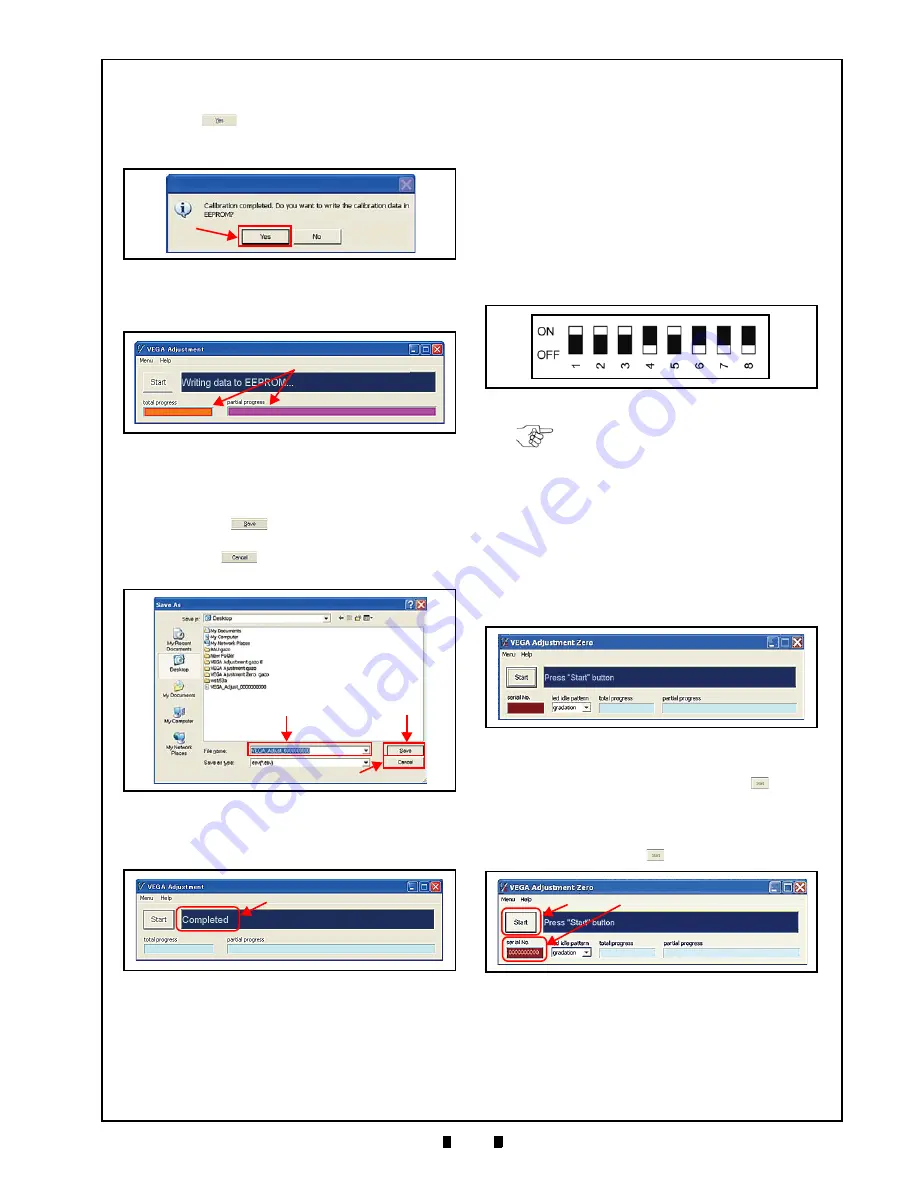
19. When the “Calibration completed.” Dialog
Message appears (Figure 6-30), click on the
“
Yes
”
Button (Figure 6-30
a
) to begin
writing the calibration results into the VEGA
Unit’s EEPROM.
20. Confirm the writing progress by checking the
a
).
21. When the calibration result data is completely
written into EEPROM, the Screen to save the data
onto the PC will appear (Figure 6-32). Click on
the “
Save
”
Button (Figure 6-32
a
) to retain
the data results (Figure 6-32
b
), or click on the
“
Cancel
”
Button (Figure 6-32
c
) to end the
Calibration Procedure without saving the data.
22. Confirm the “
Completed
” Message (Figure 6-33
a
) on the Screen.
This completes the Calibration Procedures.
VEGA_Adjustment_Zero.exe Program
Use
To use the VEGA_Adjustment_Zero.exe Program,
proceed as follows:
1. Copy the VEGA_Adjustment_Zero.exe Program
into the PC Folder.
2. Turn the VEGA Unit power
OFF
.
3. Confirm that the interconnection for performing
the VEGA calibration with the PC (See “Tool
Requirements” on page 6-1).
4. Set DIP Switch DS1 Switches #1, #2, #3 and #5
to
ON
(Figure 6-34).
5. Turn the VEGA power
ON
. The Front LED will
slowly flash at a
Green
Color rate.
Set DIP Switch Block DS1 Switch #1 to
OFF
. The
Front Panel LED will begin to flash in a
Cyan
,
White, and
Blue
Color sequence.
6. Launch the VEGA_Adjustment_Zero.exe Pro-
gram. The VEGA Adjustment Screen (Figure 6-
35) will appear when the application is active.
7. Click on the “
Serial No.
” Text Entry Field (Figure
a
) located just below the “
Start
”
Button
b
).
8. Type in the new VEGA Serial Number as a
continuous Character String with no spaces.
9. Click on the “
Start
”
Button.
a
Figure 6-30
Request Writing Data to EEPROM
a
Figure 6-31
Writing EEPROM Data Progress
Figure 6-32
b
a
c
Figure 6-32
Save As Screen
Figure 6-33
a
Figure 6-33
VEGA Adjustment Complete Screen
Figure 6-34
DIP Switch Block DS1 Initial Settings
NOTE: DIP Switch Block DS2 and DS3
settings are not required for this
procedure.
Figure 6-35
VEGA Adjustment Screen
Figure 6-36
Serial No. Input Field Location
b
a
Figure 6-36
Serial No. Input Field Location


