P/N 960-100929R_Rev. 3 {EDP #148849}
© 2012, Japan CashMachine Co., Limited
6 - 1 3
Calibration and Testing
iVIZION® SeriesNext-Generation Banknote Acceptor Unit
Section 6
4. Check the Status LED’s condition. When the
Status LED Indicator blinks in a
Red
,
Green
, and
Blue
Color sequence, the Status LED is perform-
ing normally.
5. Mouse-click on the “
Stop
” Screen Button
(See Figure 6-61 b) to end the LED Indicator
Test.
6. Mouse-click on the “
Exit
” Screen Button
(See Figure 6-61 c) to return to the “
Test Item
Select
” Screen.
S
ENSOR
ON/OFF T
EST
Perform the following steps to perform the Sensor
ON/OFF Test.
1. Launch
the
“
Test Item Select
” Screen again
(Refer to “PC Performance Test Preparation” on
page 6-11 of this Section).
2. Mouse-click on the “
Sensor ON/OFF Test
”
Screen Button (See Figure 6-58 f).
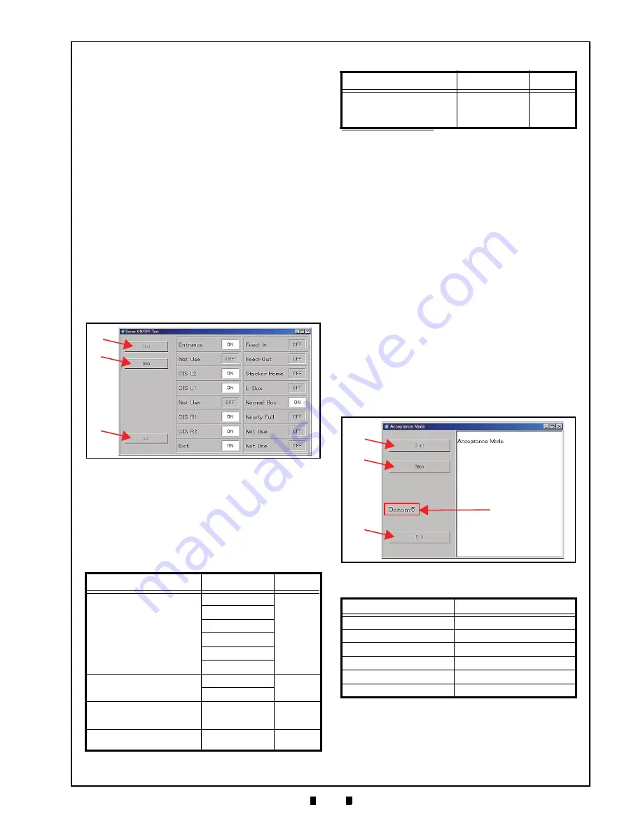
3. Mouse-click on the “
Start
” Screen Button
(See Figure 6-62 a) to begin the Sensor ON/OFF
Test. The current testing condition is indicated in
a column adjacent to the Function being tested on
Five (5) actions are required to check all twelve
(12) Sensors in the iVIZION
®
Unit. Refer to
Table 6-4 for each action regarding the related
Sensor being tested.
When the desired test action is complete, the
resulting condition of each Sensor is indicated by
its Screen condition turning “ON”.
4. Mouse-click on the “
Stop
” Screen Button
(See Figure 6-62 b) to end the Sensor ON/OFF
Test.
5. Mouse-click on the “
Exit
” Screen Button
(See Figure 6-62 c) to return to the “
Test Item
Select
” Screen.
B
ANKNOTE
A
CCEPTANCE
T
EST
Perform the following steps to test the transporta-
tion, validation, stacking and reject sequential per-
formance and Vend Signal Output functions of the
iVIZION
®
Unit.
1. Launch the “
Test Item Select
” Screen again
(Refer to “PC Performance Test Preparation” on
page 6-11 of this Section).
2. Mouse-click on the “
Accept Test
” Screen Button
3. Mouse-click on the “
Start
” Screen Button
(See Figure 6-63 a) to begin the Banknote Trans-
port Test.
4. Insert a Banknote into the iVIZION
®
Unit.
The Banknote’s Denomination will be indicated
on a Screen similar to Figure 6-63d.
5. Mouse-click on the “
Stop
” Screen Button
(See Figure 6-63 b) to quit from the related Test
Screen.
6. Mouse-click on the “
Exit
” Screen Button
(See Figure 6-63 c) to return the “
Test Item
Select
” Screen.
Table 6-4
Sensor Actions and Conditions
Action
Sensor
Condition
Open the Acceptor Unit’s
Upper Guide
Entrance
OFF
→
ON
CIS L2
CLS L1
CIS R1
CIS R2
Exit
Open the Transport Unit’s Upper
Guide
Feed-In
OFF
→
ON
Feed-Out
No Action Required (Seat the
Cash Box correctly in place)
Cash Box
(Large Cash Box or
Standard Cash Box)
OFF
→
ON
Remove the Cash Box
from the Unit
Nearly Full
OFF
→
ON
Figure 6-62
Sensor ON/OFF Test Screen
a
b
c
Hold-down the Pusher Plate and
slide a 80x50mm piece of
Cardboard in-between the Frame
Outer LR and the Pusher Plate
*
Home Position
OFF
→
ON
*. Review Figure 6-40 and Figure 6-41 on page 6-8 regarding how to set
the Cardboard in place.
Table 6-5
Denomination Valuation List
Denomination
Value Indication
$1
1
$5
5
$10
10
$20
20
$50
50
$100
100
Table 6-4
Sensor Actions and Conditions (Cont.)
Action
Sensor
Condition
Figure 6-63
Denomination Indication Location
a
b
c
d
KF srl | www.keyfuture.com | Phone +39 059313920
KF srl | www.keyfuture.com | Phone +39 059313920


