P/N 960-100929R_Rev. 3 {EDP #148849}
© 2012, Japan CashMachine Co., Limited
6 - 8
Section 6
iVIZION® SeriesNext-Generation Banknote Acceptor Unit
Calibration and Testing
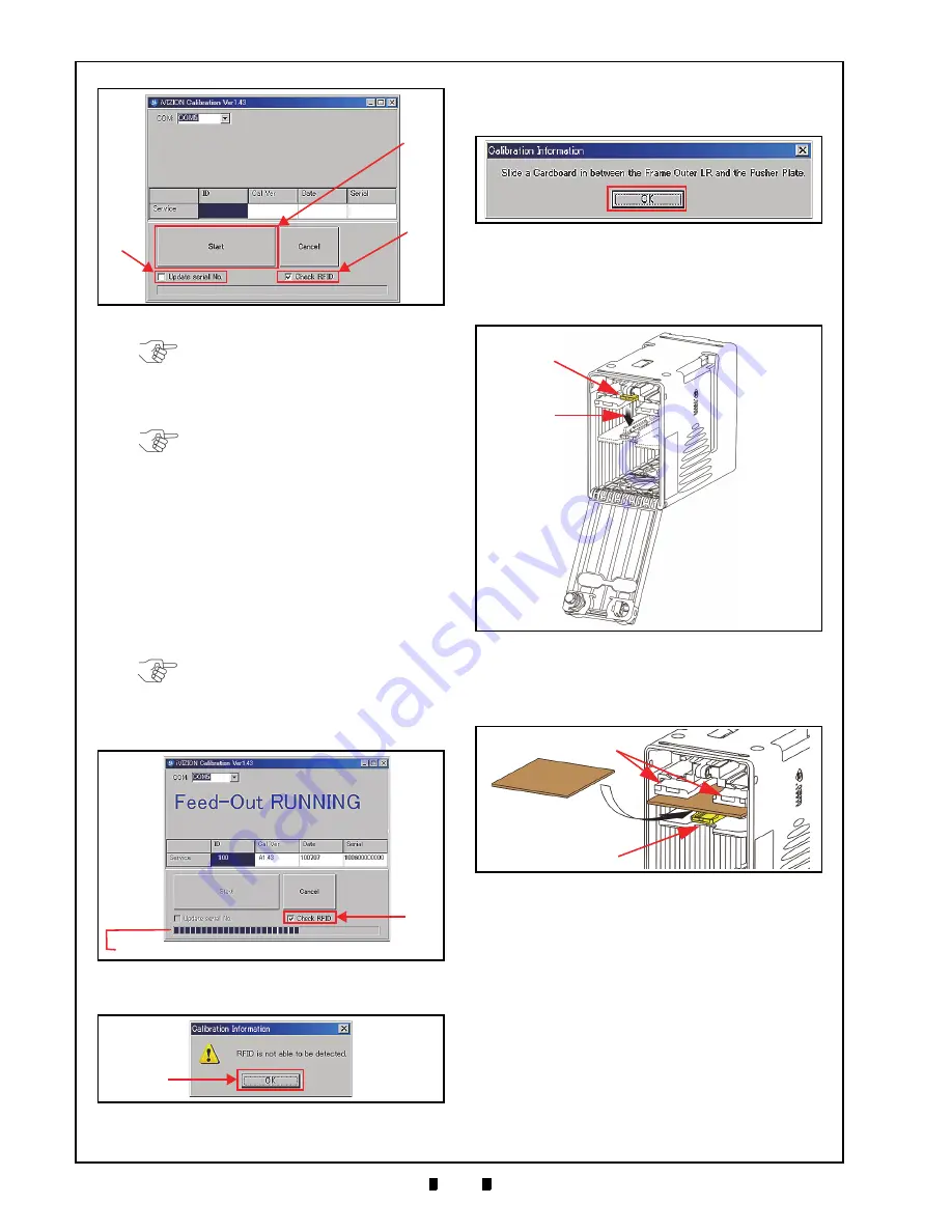
7. Mouse-click on the “
Start
” Screen Button
(See Figure 6-36 a) to begin the following three
(3) sequential Sensors Calibration Procedures:
a). Cash Box Sensor
b). Nearly Full Sensor
c). Feed-Out Sensor.
Calibration will be performed in the above alpha-
betic order while one of either “
Box RUNNING
”,
“
Nearly Full RUNNING
” and “
Feed-Out RUNNING
”
messages is showing on the Screen (See Figure
Once the three (3) Sensor Calibration Procedures
are complete, the “
Calibration Information
”
Screen shown in See Figure 6-39 will re-appear.
8. Remove the Cash Box to perform the Home
Position Sensor Calibration Procedure.
9. Open the Cash Box and press down on the Pusher
Release Plate (See Figure 6-40 a & b).
10. Hold the Pusher Plate down (See Figure 6-41 a)
and slide a 80x50mm piece of Cardboard
(See Figure 6-41 b) in between the Frame Outer
LR Guides (Figure 6-41 c) and the Pusher Plate.
11. Reseat the Cash Box back into its Frame position.
12. Mouse-click on the “
OK
” Screen Button (Review
Figure 6-39 a) to begin the following four (4)
Sensor Calibration Procedures:
a). Home Position Sensor
b). Feed-In Sensor
c). Entrance Sensor
d). Exit Sensor.
Calibration will be performed in the above alpha-
numeric order while one of “
Home Position
RUNNING
”, “
Feed-In
RUNNING
”, “
Entrance
RUNNING
” or “
Exit
RUNNING
” messages is show-
ing on the Screen (See Figure 6-42).
Figure 6-36
iVIZION Calibration Ver.X.XX Screen
a
b
c
NOTE: Writing a Serial No. can be
performed after a Calibration is
completed. To do so, Click on the “
Update
serial No.
” Check-box (See Figure 6-36 b)
if the iVIZION Device needs its current
Serial No. written.
NOTE: If the RFID Board is not featured
within the iVIZION Device, remove the
check in the “
Check RFID
” Check-box.
NOTE: If the “
Check RFID
” Check-box
shown in Figure 6-37a is un-checked, the
“
Calibration Information
” Screen shown
in Figure 6-38 will not appear. When
present, Mouse-Click on the “
OK
” Screen
Button to begin the Calibration Procedure.
Figure 6-37
Feed-Out Calibration Proceeding
Screen
a
NOTE: The Barograph does not indicate a Calibration in progress.
Figure 6-38
Calibration Information Screen 1
a
Figure 6-39
Calibration Information Screen 2
a
Figure 6-40
Pusher Plate Release Location
a
b
Figure 6-41
Cardboard Setting Location
a
a
b
Slide In
c
Cardboard


