


neoVI FIRE 2 User’s Guide
36
© 2016 Intrepid Control Systems, Inc.
Version 2.1 - October 10, 2016
3.3 Hardware Hookup Diagrams
Hookup diagrams show you at a glance how to physically connect your neoVI FIRE 2 to
vehicle networks and your PC. Below you will find first a hookup diagram for using the FIRE 2
without an OBD cable, and then five additional ones showing the connections for each of the
OBD cable options discussed in Section 2.5.
Four of the OBD cables—the neoVI-OBD-1, neoVI-OBD-MULTI, neoVI-OBD-MULTI Right
Angle, and neoVI FIRE/RED J1939—are connected to the DB-25 of the FIRE 2 Ethernet Cable
Adapter and then attach to an OBD port on a vehicle or network test bench. The fifth, the FIRE
2 OBD Cable with DoIP Support, replaces the FIRE2 Ethernet Cable Adapter.
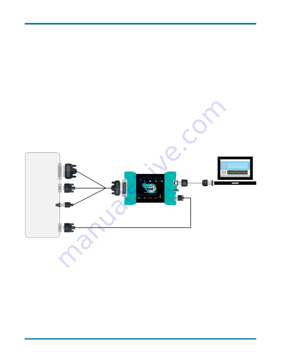
Basic Hardware Hookup Diagram
Figure 46
shows the basic hardware configuration of the neoVI FIRE 2, with the USB cable
connecting the device to the PC, and the FIRE 2 Ethernet Cable Adapter and µDB-9 to DB-9
cables linking it to vehicle networks.
Vehicle
Networks
Figure 46: Basic FIRE 2 Hardware Hookup Diagram.
This diagram shows basic connections with no OBD cable.
OBD Hardware Hookup Diagram - neoVI-OBD-1 Cable
In Figure 47 you can see the basic hardware setup from Figure 46 but with the addition of the
neoVI-OBD-1 cable.


