background image

-363-

10 Application Cases

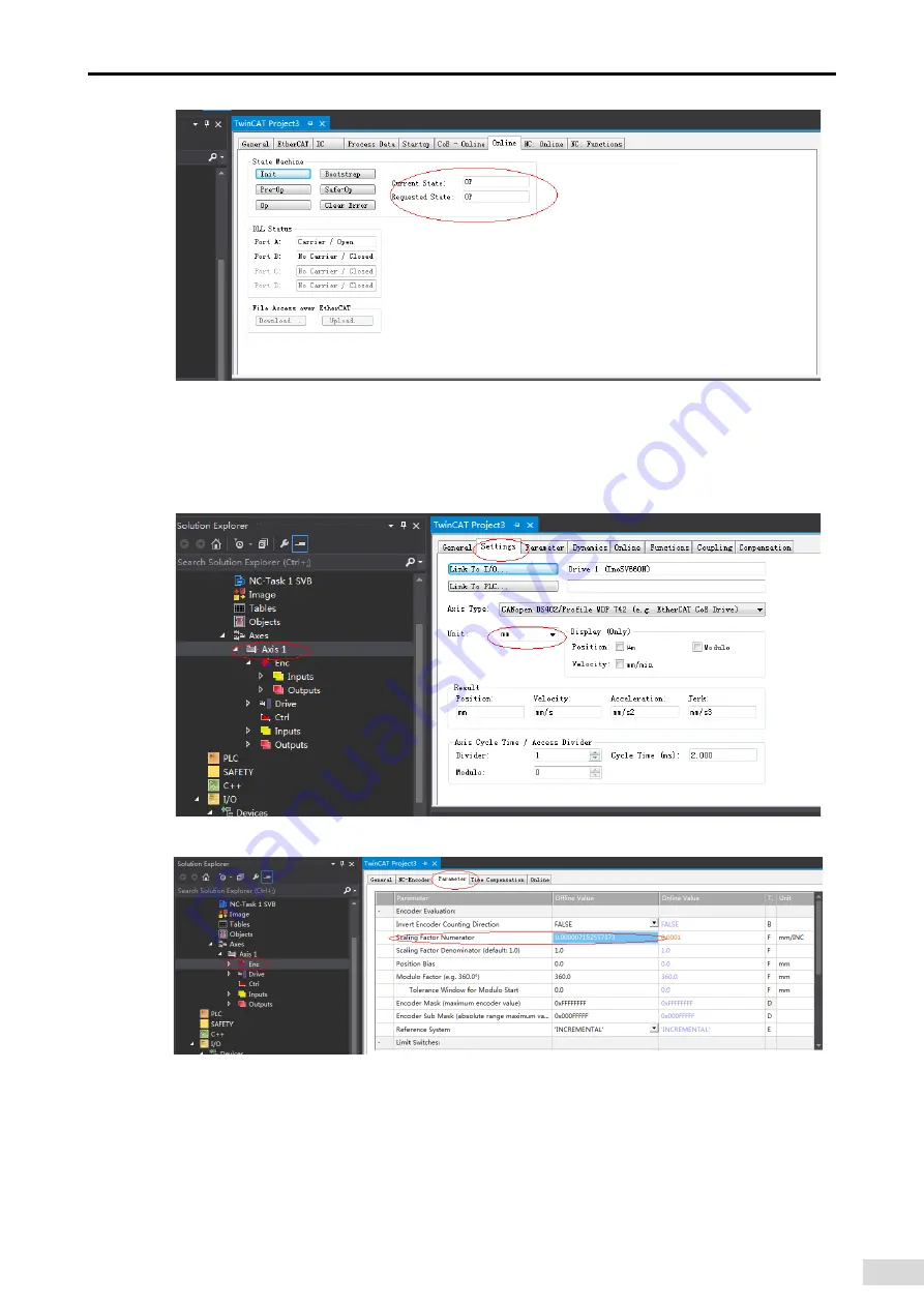
7) Controlling the servo drive through NC controller or PLC program

7-1) Servo drive running in the CSP mode

a) 

Set the unit.

The unit is "mm" during testing.

b) 

Set the scaling factor.


Scaling factor: distance corresponding to the encoder pulses per position feedback

For example, 8388608 pulses per motor revolution corresponds to the distance of 60 mm, and the scaling 
factor is: 60/8388608 = 0.000007152557373 mm/Inc.

Summary of Contents for SV660

Page 1: ...y Co Ltd Add Building E Hongwei Industry Park Liuxian Road Baocheng No 70 Zone Bao an District Shenzhen Tel 86 755 2979 9595 Fax 86 755 2961 9897 Service Hotline 400 777 1260 http www inovance com Suz...

Page 2: ...ad through this user guide For concerns regarding product functions or performance contact Inovance for technical support Safety Instructions The drawings in the user guide are sometimes shown without...

Page 3: ...4 35 EU Servo drive EN 61800 5 1 IEC 61800 5 1 Servo motor EN 60034 1 RoHS directive 2011 65 EU EN 50581 NOTE The preceding certification are complied with only when the EMC related electrical install...

Page 4: ...4 Specifications of the Regenerative Resistor 23 1 2 Introduction to the Servo Motor 24 1 2 1 Motor Nameplate and Model Number 24 1 2 2 Components 25 1 2 3 Technical Specifications 26 1 3 Servo Syste...

Page 5: ...Signal Terminal CN1 68 3 5 1 DI DO signals 69 3 5 2 Wiring of the Brake 72 3 6 Wiring of Communication Signals CN3 CN4 74 3 6 1 Pin Definition of the Communication Signal Connector 75 3 6 2 Selection...

Page 6: ...Stop 128 5 7 Conversion Factor Setting 132 6 Gain Tuning 135 6 1 Overview 135 6 2 Inertia Auto tuning 136 6 2 1 Offline Inertia Auto tuning 137 6 2 2 Online Auto tuning 139 6 3 Instructions for ETune...

Page 7: ...3 6 8 Mechanical Characteristic Analysis 175 6 8 1 Overview 175 6 8 2 Operating Procedures 176 7 Control Mode 178 7 1 Servo Drive State Setting 179 7 1 1 Control Word 6040h 181 7 1 2 Status Word 6041h...

Page 8: ...s 206 7 6 6 Function Block Diagram 209 7 7 Profile Velocity Mode PV 209 7 7 1 Configuration Block Diagram 209 7 7 2 Related Objects 209 7 7 3 Related Function Settings 210 7 7 4 Recommended Configurat...

Page 9: ...ons 288 8 1 Overview of the EtherCAT Protocol 288 8 2 System Parameters 289 8 2 1 Parameter Address Structure 289 8 2 2 System Parameter Settings 289 8 3 EtherCAT Communication Basis 290 8 3 1 EtherCA...

Page 10: ...Leakage Current 378 11 1 8 Solutions to Common EMC Problems 379 11 1 9 UL Certification 380 11 2 List of Object Groups 381 Description of Object Groups 381 Object Group 1000h 381 Object Group 2000h 3...

Page 11: ...the notice will result in severe personal injuries or even death WARNING Indicates that failure to comply with the notice may result in severe personal injuries or even death CAUTION Indicates that f...

Page 12: ...ment damage Never stand or stay below the equipment when the equipment is lifted by hoisting equipment Installation WARNING Thoroughly read the safety instructions and user guide before installation D...

Page 13: ...ower on make sure that the equipment is installed properly with reliable wiring and the motor can be restarted Before power on make sure that the power supply meets equipment requirements to prevent e...

Page 14: ...sult in an electric shock Before inspection and repair cut off all equipment power supplies and wait at least 15 minutes WARNING Require for repair services according to the product warranty agreement...

Page 15: ...afe equipment operation and maintenance comply with safety signs on the equipment and do not damage or remove the safety labels The following table describes the safety signs Safety Sign Description D...

Page 16: ...k type Code Voltage Class S 220 V T 380 V Rated output current 8 4 A 8R4 Symbol 12 A 012 17 A 017 21 A 021 26 A 026 6 6 A 6R6 5 5 A 5 R 5 1 6 A 1R6 2 8 A 2R8 3 5 A 3R5 5 4 A 5R4 Rated output current S...

Page 17: ...settings 3 Operation buttons MODE Used to switch parameters in sequence Used to increase the value of the blinking digit Used to decrease the value of the blinking digit Used to shift the blinking di...

Page 18: ...C Terminals for connecting external regenerative resistor Connected between P and C when an external regenerative resistor is needed 10 U V W Servo motor connecting terminals Connected to U V and W ph...

Page 19: ...nput terminals See the nameplate for the power input of the rated voltage class Note 750 W servo drives Single phase 220 V input with 220 V power supply connected to L1 and L2 850 W servo drives Singl...

Page 20: ...B Size C Size D Servo drive model SV660N S6R6 S7R6 S012 Continuous output current Arms 6 6 7 6 11 6 Maximum output current Arms 16 5 23 32 Main circuit power supply Three phase 200 240 VAC 10 to 10 5...

Page 21: ...the condition for non stop at rated torque load Speed loop bandwidth 2 5 kHz Torque control accuracy Repetitiveness 2 Soft startup time 0s to 65s The acceleration and deceleration can be set separatel...

Page 22: ...nication protocol EtherCAT protocol Available services CoE PDO SDO Synchronization mode DC Distributed clock Physical layer 100BASE TX Baud rate 100 Mbit s 100Base TX Duplex mode Full duplex Topologic...

Page 23: ...external DI signal or the motor phase Z signal changes High resolution encoder The encoder is of high performance with resolution up to 8388608 PPR Mechanical characteristics analysis Analyzes the re...

Page 24: ...osition comparison output Outputs a DO signal with designated width after the servo drive reaches the preset target position Black box function Captures the data before and after the designated condit...

Page 25: ...t multi turn absolute encoder Code Voltage Class B 220 V D 380 V Code Product Type S Servo Servo motor Code Product Generation 1 1st generation Code Type 1 Low inertia small capacity Lowinertia medium...

Page 26: ...Front outlet Cable outlet direction Rear outlet Flange mounting surface Screw mounting hole Shaft extension with key Flange mounting surface Screw mounting hole Shaft extension with key Figure 1 5 MS1...

Page 27: ...1H1 20B30CB 0 2 0 64 2 24 1 5 5 8 MS1H1 40B30CB 0 4 1 27 4 46 2 8 10 1 MS1H4 40B30CB 0 4 1 27 4 46 2 8 10 1 MS1H1 75B30CB 0 75 2 39 8 36 4 8 16 9 MS1H4 75B30CB 0 75 2 39 8 36 4 8 16 9 MS1H3 85B15CB 0...

Page 28: ...ime s 120 230 130 80 140 40 150 30 160 20 170 17 180 15 190 12 200 10 210 8 5 220 7 230 6 240 5 5 250 5 300 3 100 150 200 250 1000 Load ratio Running time s 300 1 10 100 Figure 1 7 Motor overload curv...

Page 29: ...92 147 MS1H3 85B15CB 686 196 5 Electrical specifications for the motor with brake Motor Model Holding Torque N m Supply Voltage VDC 10 Release Time ms Close Time ms Backlash MS1H1 05B 10B 0 32 24 20 3...

Page 30: ...orque N m 0 6 0 3 1 2 MS1H1 10B30CB A B 0 2000 3000 4000 5000 6000 Speed RPM 1000 0 1 8 Torque N m 1 2 0 6 2 4 MS1H1 20B30CB A B 0 2000 3000 4000 5000 6000 Speed RPM 1000 0 3 6 Torque N m 2 4 1 2 4 8...

Page 31: ...ing area Short term working area A B 2000 3000 4000 5000 6000 Speed RPM 1000 0 3 6 Torque N m 2 4 1 2 4 8 MS1H4 40B30CB A B 0 2000 3000 4000 5000 6000 Speed RPM 1000 0 7 5 Torque N m 5 2 5 10 MS1H4 75...

Page 32: ...02 400 W 40B30CB 60 S2R8 A 00003 550 W 55B30CB 80 S5R5 B 00005 750 W 75B30CB 80 S5R5 B 00005 1000 W 10C30CB 80 S7R6 C 00006 1000 W MS1H2 Low inertia medium capacity 10C30CB 100 S7R6 C 00006 5000 RPM 1...

Page 33: ...15CD 180 T017 E 10005 5500 W 55C15CD 180 T021 E 10006 7500 W 75C15CD 180 T026 E 10007 1 4 Cable Models Table 1 1 Cables for MS1 terminal type Z motors with front cable outlet Cable Type Cable Length m...

Page 34: ...tors with front cable outlet Cable Type Cable Length m 3 0 5 0 10 0 Power cable without brake S6 L M100 3 0 S6 L M100 5 0 S6 L M100 10 0 Power cable with brake S6 L B100 3 0 S6 L B100 5 0 S6 L B100 10...

Page 35: ...or parallel communication of multiple servo drives S6 L T03 0 0 Cable for communication between the servo drive and the host controller 1 6 Connector Kit Connector Kit Outline Drawing S6 C6 DB15C plug...

Page 36: ...erved Reserved PS PS Enclosure PE System grounding PE Motor grounding terminal CN3 CN4 CN5 Serial communication terminal used to connect the software tool CN6 Functional safety terminal connected to e...

Page 37: ...pecially when the power supply is used to power up multiple servo drives or brakes Insufficient power supply will lead to insufficient supply current resulting in failure of the servo drive or the bra...

Page 38: ...between the servo drive and the interior surface of the electric cabinet and other machines Failure to comply will result in a fire or device faults Do not put heavy objects on the device Failure to c...

Page 39: ...bration Below 4 9 m s2 Impact Below 19 6 m s2 IP rating IP20 Altitude Below 1000 m 2 1 3 Dimension Drawings Size A SV660NS1R6I SV660NS2R8I Front view Left view Rear view Top view 40 3 3 170 150 75 160...

Page 40: ...60NS012I SV660NT8R4I SV660NT012I 3 M4 screw through hole 80 1 170 4 183 75 71 160 5 Front view Top view Rear view Left view Retaining screw 3 M4 Recommended tightneing torque 1 2 N M Figure 2 4 Outlin...

Page 41: ...ll the cooling fan on the upper part of the servo drive to avoid excessive temperature rise in a certain region and maintain an even temperature inside the electric cabinet Installation When installin...

Page 42: ...lectric shock or malfunction due to interference Cable Direction As shown in the following figure route the servo drive cables with outlet facing downwards to prevent any liquid from flowing into the...

Page 43: ...able gases and combustible materials such as the hydrogen sulfide chlorine anmonia sulphur gas chloridize gas acid soda and salt Use the servo motor with oil sealing when the motor is used in a place...

Page 44: ...extension during installation Failure to comply will damage the encoder Use the screw hole at the shaft end when mounting a pulley to the servo motor shaft with a keyway To fit the pulley insert a do...

Page 45: ...of the servo motor when the application location is exposed to water drops except the shaft opening Flange surface Shaft opening Refers to the clearance of the shaft extension Shaft Mount the motor wi...

Page 46: ...ody instead of by the cable Failure to comply may damage the connector or cable 6 If flexible cables are used do not apply stress on the connector during wiring Failure to comply may damage the connec...

Page 47: ...60 30 0 5 70 4 5 5 44 7 5 3 0 5 0 5 0 35 MS1H4 40B30CB 34Z 128 60 30 0 5 70 4 5 5 44 7 5 3 0 5 0 5 0 35 Motor Model S LB TP LK KH KW W T Weight kg MS1H1 20B30CB 31Z 14 50 M5x8 16 5 11 5 5 5 0 78 MS1H1...

Page 48: ...3 0 5 0 5 0 35 MS1H4 75B30CB 34Z 147 5 80 35 0 5 90 4 7 54 7 7 3 0 5 0 5 0 35 Motor Model S LB TP LK KH KW W T Weight kg MS1H1 75B30CB 31Z 19 70 M6x20 25 15 5 6 6 6 2 18 MS1H1 75B30CB 34Z 19 70 M6x20...

Page 49: ...4 9 2 M5 103 72 5 74 125 161 14 Motor Model LE LJ LB S TP LK KH KW W T Weight kg MS1H3 85B15CB Z 4 0 5 0 75 110 22 M6x20 36 18 0 2 8 8 7 7 8 NOTE The unit for the dimensions in the preceding table is...

Page 50: ...e faulty Do not connect output terminals U V and W of the servo drive to a three phase power supply Failure to comply may cause physical injuries or fire accidents Do not connect the motor connecting...

Page 51: ...circuit power supply and switch from S ON to S OFF after a warning signal is detected Connect the servo drive to the motor directly Do not use an electromagnetic contactor during wiring Failure to com...

Page 52: ...O2 DO1 DI1 DI3 DI4 D01 24V COM COM DI5 DO2 15 10 5 11 6 1 CN3 CN4 16 RD TD TD RD 9 RD TD TD RD 1 8 Encoder signal terminal CN2 Main circuit input terminal CN8 Reserved Reserved Enclo sure Figure 3 1 T...

Page 53: ...D RD 1 8 16 Encoder signal terminal CN2 Main circuit input terminal CN8 Reserved Reserved Enclo sure Figure 3 2 Terminal pin layout of servo drives in size B The preceding figure shows the pin layout...

Page 54: ...of servo drives in size B No Component Name Description 1 L1 L2 L3 Power input terminals See the nameplate for the power input of the rated voltage class Note 750 W servo drives Single phase 220 V inp...

Page 55: ...pole of the bus directly Failure to comply will damage the servo drive and cause a fire Do not select any resistor with resistance lower than the minimum permissible value Failure to comply will resu...

Page 56: ...ted Output Current Out U V W PE mm2 AWG mm2 AWG mm2 AWG Single phase 220 V 1 Size A SV660NS1R6I 2 30 2x0 5 20 1 60 2x0 5 20 0 50 20 2 SV660NS2R8I 4 00 2x0 5 20 2 80 2x0 5 20 0 50 20 3 Size B SV660NS5R...

Page 57: ...pplications the relation between AWG specification and the allowable current is shown in the following table Note that the values listed in the table cannot be exceeded during use Table 3 8 Specificat...

Page 58: ...n Servo alarm output relay Servo alarm indicator Servo alarm signal output 660N servo drive PG M Figure 3 7 Main circuit wiring of single phase 220 V models NOTE 1KM Electromagnetic contactor 1Ry Rela...

Page 59: ...current into consideration When the temperature inside the cabinet is higher than the temperature limit of the cable it is recommended to use a Teflon cable with a higher temperature limit As the sur...

Page 60: ...frequently will deteriorate the performance of the main circuit components inside the servo drive Use a grounding cable with the same cross sectional area as the main circuit cable If the cross sectio...

Page 61: ...ctor Terminal Pin Layout Applicable Motor Frame Note Black 6 pin connector 4 3 2 1 5 6 Pin No Signal Name Color 1 PE Yellow Green 2 W Red 3 V Black 4 U White 5 Brake Polarity insensitive Brown 6 Brake...

Page 62: ...6 pin connector 4 5 6 1 2 3 Pin No Signal Name Color 1 U White 2 V Black 4 W Red 5 PE Yellow Green 3 Brake polarity insensitive 6 Recommendations Plastic housing MOLEX 50361736 Terminal MOLEX 39000061...

Page 63: ...in No Signal Name B U B U Blue I V I V Black F W F W Red G PE G PE Yellow Green C Brake polarity insensitive E 100 130 3 4 Connection of the Servo Drive and Servo Motor Encoder Cables 1 Installing the...

Page 64: ...ce can cause liquid leakage The electrolyte inside the battery is corrosive and conductive not only corroding surrounding components but also giving rise to the danger of short circuit Therefore repla...

Page 65: ...atus and transmit receive data after a delay of 5s Switching from standby mode to normal operation mode upon power on requires the motor to rotate at a speed less than 10 RPM Otherwise the servo drive...

Page 66: ...e shows the wiring diagram of absolute encoder cables which is similiar to that of incremental encoder without a battery box cables Incremental encoder cables need to be purchased separately NOTE The...

Page 67: ...attery included S6 C36 Table 3 16 Cable connectors of the terminal type motor encoder Outline Drawing and Pin Layout of the Connector Applicable Motor Frame 1 Servo Drive Side Motor Side 6 pin male Le...

Page 68: ...lead wire type 80 lead wire type 9 pin connector 7JFXFE GSPN UIJT TJEF 1 2 3 4 5 6 7 8 9 Pin No Signal Name Type 1 Battery 4 Battery 3 PS Twisted pair 6 PS 9 5V 8 GND 7 Shield Recommendations Plastic...

Page 69: ...13 12 11 3 DO3 DO3 DI2 DO2 DO1 DI1 DI3 DI4 D01 24V COM COM DI5 DO2 15 10 5 11 6 1 Figure 3 14 Pin layout of CN1 terminal connector CN1 terminal Plastic housing of the plug on the cable side DB15P SZT...

Page 70: ...24 V power supply voltage range 20 V to 28 V maximum output current 200 mA COM 14 COM 13 Power input terminal 12 V to 24 V DO1 S RDY 1 Servo ready DO1 S RDY 6 DO2 ALM 3 Fault DO2 ALM 2 DO3 BK 5 Brake...

Page 71: ...C DI1 CMD1 24 V COM 10 13 15 Relay External 0 V 24 V power supply COM Two power supplies used 4 7 k 2 The host controller provides open collector output For use of the internal 24 V power supply of th...

Page 72: ...ternal 0 V PNP NOTE PNP and NPN input cannot be used mixedly 2 DO circuit DO1 to DO5 circuits are the same The following description takes DO1 circuit as an example 1 The host controller provides rela...

Page 73: ...ted The maximum allowable voltage and current of the optocoupler output circuit inside the servo drive are as follows Voltage 30 VDC Current DC 50 mA 3 5 2 Wiring of the Brake The brake is used to pre...

Page 74: ...r Brake Motor Noise filter Three phase 220 VAC 380 VAC L1 L2 L3 Three phase U V W M CN2 PG BK Figure 3 16 Wiring of the brake Pay attention to the following precautions during wiring When deciding the...

Page 75: ...EtherCAT EtherCAT Servo drive EtherCAT communication cable Servo drive to PLC communication cable 39 40 2 1 CN5 CN3 Ether NET E ther CAT CN1 RS 485 C N2 CAN CANERR CANRUN BF SF ERR RUN RUN STOP MFK 0...

Page 76: ...g 4 and 5 6 RD Data receiving 7 and 8 9 TD Data transmitting 10 TD Data transmitting 11 RD Data receiving 12 and 13 14 RD Data receiving 15 and 16 3 6 2 Selection of Communication Cables Principle for...

Page 77: ...ability Ambient temperature 30 to 60 resistant to industrial oil and corrosive acid and alkali EMC test standard GB T 24808 2009 3 6 3 Communication Connection with PC RS232 Communication Connect the...

Page 78: ...ription Terminal Pin Layout 2 PC RXD PC receiving end 1 2 3 4 5 6 7 8 9 3 PC TXD PC transmitting end 5 GND Ground Enclosure PE Shield If the host controller provides only the USB interface use the ser...

Page 79: ...ference ground 2 24V 24 V 24 V power supply for commissioning 3 STO1 Control input for STO1 4 STO2 Control input for STO2 2 Two isolated inputs are configured to dual channel inputs of STO function ST...

Page 80: ...ive can operate normally only if the input status of STO1 and STO2 are both 1 or H If the input status of either STO1 or STO2 or both is 0 or L the servo drive cannot run Electrical characteristics of...

Page 81: ...s must be well protected routed and clamped where practicable Ensure that there is no pulling or pinching on the cables during installation For cabling the DIs of the STO to avoid the faults that comm...

Page 82: ...rge machine When the servo drive is placed near a high frequency generator install a noise filter on the input side of the power cable 3 8 1 Anti interference Wiring Example and Grounding The servo dr...

Page 83: ...ces if necessary To ensure the filtering effect abide by the following requirements when installing and wiring the noise filter Do not put the input and output cables of the noise filer in the same du...

Page 84: ...igure 3 25 Grounding cable of the noise filter 3 9 Precautions for Use of Cables Do not bend or apply any tension to cables The conductor of a signal cable is only 0 2 mm or 0 3 mm in diameter Handle...

Page 85: ...elow 60 Do not use cables with different sizes together This is to prevent thin cables from being crushed by thick cables If thick and thin cables need to be used together use a spacer plate to separa...

Page 86: ...on MODE Used to switch the mode and return to the previous menu UP Used to increase the value of the blinking digit DOWN Used to decrease the value of the blinking digit SHIFT Used to shift the blinki...

Page 87: ...2 2 Display Mode Switchover Power on Status display Parameter display Monitoring display Fault display MODE Switched to group H0B MODE MODE MODE MODE SET Motor at standstill After you set H02 32 the...

Page 88: ...the servo drive in hexadecimal digits 1 Profile position control 3 Profile velocity mode 4 Profile torque mode 6 Homing mode 8 Cyclic synchronous position mode 9 Cyclic synchronous velocity mode A Cy...

Page 89: ...ymbol For example 9999 and 65535 are displayed as follows 2 Signed number of more than 4 digits or unsigned number of more than 5 digits Such numbers are displayed from low to high digits through seve...

Page 90: ...F InIt parameter restored to default setting Parameter initialization in progress H02 31 1 The servo drive is in the process of parameter initialization After parameter initialization is done switch o...

Page 91: ...ter the servo motor runs the keypad switches from servo status display mode to parameter display mode and displays the parameter No defined by H02 32 in group H0B For example if H02 32 is set to 00 th...

Page 92: ...responding level status of the three DOs Upper LED segment turned on High level indicated by 1 Lower LED segment turned on Low level indicated by 0 The value of H0B 05 read by the software tool is a d...

Page 93: ...s encoder unit Sum of pulses fed back by the encoder encoder unit Display of 10000 encoder units SHIFT H0B 17 Feedback pulse counter 32 bit decimal value Encoder unit Counts and displays the number of...

Page 94: ...st fault 2 2nd to last fault 9 9th to last fault 0 Display of present fault H0B 34 Fault code of the selected fault Displays the fault code defined by H0B 33 When there is no fault H0B 34 displays Er...

Page 95: ...en the fault defined by H0B 39 occurred When there is no fault H0B 39 displays 0 Display of 4 60 A H0B 40 Bus voltage upon occurrence of the selected fault V Displays the DC bus voltage of the main ci...

Page 96: ...and the corresponding decimal value is 0 Display of H0B 43 0x0003 DO3 DO1 DO2 High 1 High 1 Low 0 H0B 53 Position deviation counter 32 bit decimal value Reference unit Position deviation Sum of input...

Page 97: ...the absolute encoder revolutions Rev Displays the present number of revolutions of an absolute encoder Display of 32767 H0B 71 Single turn position feedback of an absolute encoder Encoder unit Display...

Page 98: ...stem works in rotation mode Display of 1 encoder unit H0B 85 Single turn position of the load in rotation mode Reference unit Displays the absolute mechanical position when the absolute system works i...

Page 99: ...value of H02 30 Set the password Er 941 displayed User password activated done Error End Power on No Yes SET button Power on again Yes No Input the set password Correct password MODE button SET UP SE...

Page 100: ...ower on SET button 1 JOG displayed indicating motor powered on and jog function available Make the motor rotate forwardly reversely End SET button UP DOWN button 2 Set and display the motor jogging sp...

Page 101: ...of the corresponding terminal must be set to level valid 02 ALM RST Fault reset Valid Fault reset under local mode Invalid Fault not reset under local mode This function is valid only in non bus contr...

Page 102: ...olute value of the filtered motor speed reaching the value of H06 16 09 BRK Brake output Valid Brake signal outputted Invalid Brake signal not outputted 10 WARN Warning Valid Warning occurs on the ser...

Page 103: ...lect the forced DI DO function During running Immediately 0 H0D 18 is used to set the forced DI level The keypad display is in hexadecimal after being converted to binary the number 1 indicates high l...

Page 104: ...s follows DI5 DI3 DI1 DI2 DI4 Low 0 High 1 High 1 High 1 High 1 Figure 4 10 DI level status corresponding to H0B 03 Exit The forced DI function is not retentive upon power off Normal DIs apply after r...

Page 105: ...DO function is valid and 0 indicates the DO function is invalid Parameters in group H04 are used to set the DO logic H0B 05 is used to monitor the DO level status The keypad displays the level and the...

Page 106: ...orresponding binary number is 110 and the value of H0B 05 Monitored DO signal read by the software tool is 6 decimal The keypad display is as follows DO3 DO1 DO2 Low 0 High 1 High 1 Figure 4 14 Displa...

Page 107: ...output enabled 60FE 02h Physical output 60FE 01h 16 DO1 1 DO1 forced output enabled DO1 forced output 0 OFF 1 ON 17 DO2 1 DO2 forced output enabled DO2 forced output 0 OFF 1 ON 18 DO3 1 DO3 forced ou...

Page 108: ...lay and Operations Exit The bus controlled forced DO signal is not retentive upon power off Normal DOs apply after restart or you can set H0D 17 Forced DI DO selection to 0 No operation to return to t...

Page 109: ...N signal Set common parameters Set parameters related to each control mode Run the servo drive at a low speed during initial running Set related parameters to achieve the desired performance Perform c...

Page 110: ...ative resistor are placed on inflammable objects 3 The servo motor installation and the shaft and mechanical connections are reliable 4 The servo motor and the machine that the servo motor is connecte...

Page 111: ...n mode by setting H0D 08 through the keypad and the keypad displays the default jogging speed which can be modified by pressing Press to enter the jogging status and the keypad displays JOG P Power on...

Page 112: ...otor shaft from rotating during non operating status of the servo drive This is to keep the motor and the mechanical motion part in locked position External force Servo motor with built in brake Preve...

Page 113: ...MS1H4 40B 1 3 24 89 5 0 25 0 34 20 50 MS1H1 75B 2 5 24 72 0 40 0 57 25 60 MS1H4 75B 2 5 24 50 1 0 40 0 57 25 60 MS1H3 85B 12 24 21 3 0 95 1 33 60 120 NOTE Do not share the same brake power supply with...

Page 114: ...if the S ON signal is off the brake output will be off immediately However within the time defined by H02 10 2002 0Bh the motor is still energized to prevent the mechanical motion part from moving du...

Page 115: ...e S ON signal is OFF and present motor speed is equal to or higher than 20 RPM the servo drive acts according to the brake time sequence in motor rotating status 65 0 After the S ON signal changes fro...

Page 116: ...ondition Immediately Data Structure Data Type Uint16 2002 0Ch Access RW Mapping Related Mode All Data Range 20 3000 RPM Default 30 Defines the motor speed threshold when the brake output signal become...

Page 117: ...be damaged The regenerative resistor can be a built in or an external one However a built in regenerative resistor cannot be used together with an external regenerative resistor The following table l...

Page 118: ...J 100 W H1 low inertia small capacity 10B30CB 0 048 0 237 9 200 W 20B30CB 0 163 0 806 9 400 W 40B30CB 0 25 1 237 18 750 W 75B30CB 1 43 6 435 26 400 W H4 medium inertia small capacity 40B30CB 0 667 3...

Page 119: ...an external regenerative resistor Derate 70 and use an external regenerative resistor Pr Yes No Pb x T Ec Use built in regenerative resistor Yes No Regenerative resistor not needed End J Inertia rati...

Page 120: ...her conditions remain the same the required regenerative resistor power will be as follows 2x N 1 x EO EC T Pb 2x 10 1 x6 4 9 2 61 4 W The calculated value is larger than the processable capacity Pa 2...

Page 121: ...resistor 2002 1Ch used cannot be smaller than the minimum permissible resistance of regenerative resistor 2002 16h Otherwise Er 922 0 will occur At stop Immediately Model dependent 65 0 Set the resis...

Page 122: ...taying in generating state When the motor torque direction is the same with the axis rotating direction the motor outputs energy to the outside In some special applications where the motor torque outp...

Page 123: ...re tool 4 After checking the preceding running conditions set related parameters properly to adapt the motor to actual working conditions 5 Perform commissioning on the servo drive according to the in...

Page 124: ...De energized About 0 1 ms to 4 ms Figure 5 11 Time sequence of coast to stop keeping de energized state at No 1 fault Fault 1 without brake DB stop keeping de energized state 0 RPM Dynamic brake outp...

Page 125: ...e sequence of DB stop keeping DB state at No 1 fault with brake 1 For the delay of brake contactor actions see 5 Electrical specif ications for the motor with brake for details Fault 1 Without brake D...

Page 126: ...tate at No 2 fault 1 After DB is enabled Fault 2 Without brake ramp to stop or stop at emergency torque keeping de energized DB state 1 Absolute value of the motor speed Motor energized Servo alarm st...

Page 127: ...Electrical specif ications for the motor with brake for details When a No 3 warning occurs on the servo drive such as Er 950 0 Forward overtravel warning and Er 952 0 Reverse overtravel warning the se...

Page 128: ...ctor ON Brake deactivated Figure 5 19 Time sequence at warnings that do not cause stop Fault reset OFF OFF ON ON 3 1 2 S ON Fault reset Servo fault status output Motor energized Stop upon fault Brake...

Page 129: ...n speed torque references This mode features smooth and controllable deceleration process with small mechanical impact Stop at emergency torque The servo drive outputs a reverse braking torque to stop...

Page 130: ...p to stop as defined by 6085h keeping DB state Stop at fault occurrence The stop mode varies with the fault type See 9 Troubleshooting for details Related parameters H02 08 Name Stop mode at No 1 faul...

Page 131: ...el is forcibly set to Stop as defined by 6085h keeping position lock state If the servo motor enters overtravel state when driving a vertical axis the workpiece may fall To prevent such risks set 2002...

Page 132: ...05 is enabled the servo drive will stop in the stop mode defined by 605Ch regardless of the running state Quick stop Quick stop applies when bit2 Quick stop in the control word 6040h is set to 0 Vali...

Page 133: ...keeping position lock state 65 0 The acceleration deceleration time cannot be set to a too small value Otherwise the stop distance may be too long causing the risk of collision 5 7 Conversion Factor...

Page 134: ...d the load shaft speed reference unit s2 is as follows Load shaft acceleration x Gear ratio 6091h Encoder resolution Motor acceleration 1000 60 x Sub index 0h Name Number of sub indexes of the gear ra...

Page 135: ...factor 1048576 x 5 10 5242880 10 524288 Therefore 6091 1h 524288 6091 2h 1 which means when the load shaft displacement is 1 mm the motor displacement is 524288 Reduce the values of 6091 1h and 6091 2...

Page 136: ...in 50 0 Load inertia ratio 30 Figure 6 1 Example of gain settings The gain is defined by the combination of multiple mutually affected parameters including position loop gain speed loop gain filter an...

Page 137: ...s the capacity in resisting the torque disturbance 6 5 6 4 Vibration suppression Mechanical resonance The mechanical resonance is suppressed through the notch 6 7 1 Low frequency resonance The low fre...

Page 138: ...forming offline inertia auto tuning The motor stroke must meet the following requirements A stroke of more than one revolutions in either forward or reverse direction is available between the mechanic...

Page 139: ...auto tuning Related parameters Para No Name Value Range Unit Function Setting Condition Effective Time Default H09 05 Offline inertia auto tuning mode 0 Bidirectional auto tuning 1 Unidirectional aut...

Page 140: ...cess of online inertia auto tuning NOTE Different values of H09 03 indicate different updating speeds of the load inertia ratio H08 15 in real time 1 H09 03 1 Applicable to applications where the actu...

Page 141: ...n other devices of the same model The ETune function is intended to be used in applications featuring small load inertia changes 6 3 2 Description of Operations 1 Operation flowchart Initialize the se...

Page 142: ...en the positive and negative limits as the maximum distance for a single action The same applies to Unidirectional reverse run mode 3 Designate the positive and negative limits allowed by the motor an...

Page 143: ...rface The adjustment mode is divided into Positioning mode and Trajectory mode The inertia ratio auto tuning is optional If you choose not to perform inertia auto tuning set the correct inertia ratio...

Page 144: ...in tuning automatically If you choose not to perform inertia auto tuning on the Start interface the servo drive starts gain tuning directly after started 6 During gain tuning if you modify the final r...

Page 145: ...cceleration deceleration time properly to enable quick positioning after auto tuning is done If the acceleration deceleration time is set to a too small value overload may occur In this case increase...

Page 146: ...t be suppressed 1 Enable vibration suppression manually to eliminate the vibration and perform ETune again 2 The auto tuned values fluctuate dramatically 2 Increase the maximum running speed and decre...

Page 147: ...the inertia ratio Start Set the gain tuning mode Click Adjustment on the menu bar and click STUNE Input the inertia ratio directly or click Manual inertia tuning to start inertia tuning When H09 00 is...

Page 148: ...to suppress vibration This mode is applicable to occasions requiring quick positioning b Adjust the stiffness level gradually during load running The present stiffness level will be written to the ser...

Page 149: ...eters Table 6 3 Parameters updated during gain auto tuning Para No Name H08 00 Speed loop gain H08 01 Speed loop integral time constant H08 02 Position loop gain H07 05 Filter time constant of torque...

Page 150: ...ver hysteresis is 30 In other modes the original setting is used 65 0 In the gain auto tuning mode the parameters updated automatically along with H09 01 and those with fixed values cannot be modified...

Page 151: ...f H08 00 Speed loop gain Increase the value of H08 00 Speed reference Actual speed Adjustment method Increase the value of H08 00 without incurring noise or vibration This helps shorten the positionin...

Page 152: ...high frequency noise and suppresses mechanical resonance Actual speed Speed reference Increase the value of H07 05 Adjustment method Ensure the cutoff frequency of the torque reference low pass filter...

Page 153: ...g time Switching to the higher gain at motor running to achieve better reference tracking performance Switching between different gain settings through an external signal to fit different conditions o...

Page 154: ...following table describes the diagrams and related parameters of different conditions Table 6 7 Description of gain switchover conditions Gain Switchover Condition Related Parameters H08 09 Condition...

Page 155: ...witchover delay Switchover delay Valid Valid 10 RPM s Valid 10 RPM s 5 Speed reference threshold 1st Speed reference Switchover level Positive switchover hysteresis 1st 2nd Negative switchover hystere...

Page 156: ...delay time Actual speed Switchover level Related parameters Para No Name Value Range Unit Function Setting Condition Effective Time Default H08 08 2nd gain mode 0 Fixed at the 1st gain P PI switchover...

Page 157: ...cations The ambient interference is strong The number of pulses received by the servo drive is smaller than those sent from the host controller Position reference filter Filters the position reference...

Page 158: ...e Range Description H05 19 Speed feedforward control selection 0 No speed feedforward 1 Internal speed feedforward Defines the speed information corresponding to the position reference encoder unit as...

Page 159: ...forward control selection 0 No torque feedforward 1 Internal torque feedforward Defines the speed reference as the torque feedforward signal source In the position control mode the speed reference is...

Page 160: ...too small value Otherwise the speed loop response may be slowed down When speed feedback overshoot occurs decrease the value of H08 24 gradually from 100 0 to a certain value at which the PDFF contro...

Page 161: ...H08 33 Related parameters Para No Name Value Range Unit Function Setting Condition Effective Time Default H08 31 Disturbance observation cutoff frequency 10 to 1700 1 Hz Defines the cutoff frequency...

Page 162: ...t gain values Cancel gain autotuning gain switchover and feedforward Set a correct inertia ratio Turn on the speed observer H08 40 1 Set the observer lter H08 29 60 Increase speed loop gain H08 00 to...

Page 163: ...to a proper value or perform inertia auto tuning A wrong inertia ratio will cause vibration Setting H08 27 H08 28 or H08 29 to a too small or too large value will cause motor vibration 6 5 8 Model Tra...

Page 164: ...Tf Current control loop Power conver sion M PG Encoder Position loop Speed loop Current loop Servo motor Host controller Servo unit Speed control loop Kp Position loop gain H08 02 Kv Speed loop gain...

Page 165: ...ng 6000 Positioning performance satisfactory End Excessive overshoot occurs Increase the value of H09 30 or decrease the value of H08 43 Yes Yes No No Yes No 2 Related parameters Para No Name Min Unit...

Page 166: ...direction NOTE Friction compensation is valid only in the position control mode Related parameters Para No Para Name Value Range Function H09 32 Gravity compensation 100 to 100 0 Defines the constant...

Page 167: ...anual gain tuning 6 6 1 Parameter Adjustment in the Position Control Mode 1 Obtain the value of H08 15 Load inertia ratio through inertia auto tuning 2 Gain parameters in the position control mode are...

Page 168: ...lter Defines the cutoff frequency of the first order low pass filter for speed feedback 4000 Hz H08 24 PDFF control coefficient Defines the coefficient of the PDFF controller 100 0 H09 30 Torque distu...

Page 169: ...except for the position speed loop gain and speed loop integral time constant 6 7 Vibration Suppression The block diagram for vibration control is as follows Speed loop control Current loop control P...

Page 170: ...se of the gain Mechanical resonance can be suppressed in the following two methods 1 Torque reference filter H07 05 H07 06 To suppress the mechanical resonance set the filter time constant to allow th...

Page 171: ...in cases where the adaptive notch cannot deliver desired performance Start Adaptive notch used One resonance frequency 3rd notch parameters updated automatically H09 18 to H09 20 Set H09 02 to 1 Two...

Page 172: ...adaptive notch may be degraded Procedures for using the manual notch 1 Step 1 Analyze the resonance frequency 2 Step 2 When using the manual notch set the frequency to the actual resonance frequency...

Page 173: ...nit Function Setting Condition Effective Time Default H09 02 Selection of adaptive notch mode 0 Parameters of the 3rd and 4th notches not longer updated 1 One adaptive notch activated parameters of th...

Page 174: ...idth level of the 4th notch 0 to 10 Defines the width level of the 4th notch During running Immediately 2 H09 23 Depth level of the 4th notch 0 to 99 Defines the attenuation level of the 4th notch Dur...

Page 175: ...Name Value Range Unit Function Setting Condition Effective Time Default H09 38 Low frequency resonance suppression frequency 1 0 to 100 0 Hz Defines the frequency for suppressing the low frequency re...

Page 176: ...01 to 2 00 Hz Defines the response of the 3rd group of low frequency resonance suppression Increasing the value of H09 50 can reduce the delay caused by suppression and improve the responsiveness Not...

Page 177: ...trong vibration during test set the current excitation to 10 during initial execution The analysis waveform may be distorted if the current excitation is too small If the vibration generated during th...

Page 178: ...177 6 Gain Tuning Figure 6 18 Example of the waveform...

Page 179: ...encoder installed on the motor or an external encoder full closed loop control The position control mode mainly applies to applications requiring positioning control such as the manipulator SMT machin...

Page 180: ...n be set Ready to switch on The servo drive is ready to run The servo drive parameters can be set Wait to switch on The servo drive is waiting to be switched on The servo drive parameters can be set R...

Page 181: ...No fault 0x0000 0x0250 11 Running Quick stop 0x0002 0x0217 12 Quick stop No fault Set 605A to a value between 0 to 3 Natural transition will be performed after stop and no control command is required...

Page 182: ...lemented for faults and warnings that can be reset 1 Other control commands are invalid 1 0 Invalid 8 Halt 1 Valid 0 Invalid 9 Operation mode specific Related to the servo drive modes 10 Reserved Unde...

Page 183: ...Manufacturer specific Undefined 9 Remote 1 Valid control word activated 0 Invalid 10 Target reach 1 Valid 0 Invalid 11 Internal limit active 1 Valid 0 Invalid 12 to 13 Operation mode specific Related...

Page 184: ...support 1 Support 0 Profile Position Mode PP 1 1 Velocity Mode VL 0 2 Profile Velocity Mode PV 1 3 Profile Torque Mode PT 1 4 N A 0 5 Homing Mode HM 1 6 Interpolated Position Mode IP 0 7 Cyclic Synchr...

Page 185: ...CST If an unsupported operation mode is set through SDO an SDO error will be returned For details see 11 2 List of Object Groups If an operation mode not supported is set through PDO this operation mo...

Page 186: ...B0 Following error actual value 0x60F4 Velocity actual value 0x606C Torque actual value 0x6077 Figure 7 3 Cyclic synchronous position mode 7 3 2 Related Objects Index hex Sub index hex Name Access Dat...

Page 187: ...sition unit If the position deviation exceeds the threshold of excessive position deviation and such status persists after the time defined by 6066h elapses EB00 0 Excessive position deviation will oc...

Page 188: ...ange Default 0 Shows the servo drive status bit Name Description 0 Ready to switch on 1 Valid 0 Invalid 1 Switch on 1 Valid 0 Invalid 2 Operation enabled 1 Valid 0 Invalid 3 Fault 1 Valid 0 Invalid 4...

Page 189: ...s the external velocity feedforward signal of EtherCAT in the CSP mode activated when 2005 14h is set to 2 60B1h can be used to reduce the position deviation during positioning After the positioning i...

Page 190: ...drive The value 100 0 corresponds to the rated motor torque Index 60F4h Name Following error actual value Setting Condition Effective Time At display Data Structure VAR Data Type INT32 Access RO Mapp...

Page 191: ...ects Index hex Sub index hex Name Access Data Type Unit Value Range Default 6040 00 Control word RW UINT16 0 to 65535 0 6041 00 Status word RO UINT16 0 6060 00 Modes of operation RW INT8 0 to 10 0 606...

Page 192: ...uration of the CSV mode is described in the following table RPDO TPDO Description 6040 Control word 6041 Status word Mandatory 60FF Target velocity Mandatory 6064 Position actual value Optional 606C V...

Page 193: ...back over the limit 12 Drive follow the command value Not supported always being 1 13 Following error Not supported always being 0 14 Manufacturer specific Undefined 15 Home find 0 Homing not complete...

Page 194: ...Torque actual value Setting Condition Effective Time At display Data Structure VAR Data Type int16 Access RO Mapping TPDO Related Mode All Value Range 0 1 Default Represents the internal torque feedb...

Page 195: ...hex Sub index hex Name Access Data Type Unit Value Range Default 6040 00 Control word RW UINT16 0 to 65535 0 6041 00 Status word RO UINT16 0 6060 00 Modes of operation RW INT8 0 to 10 0 6061 00 Modes...

Page 196: ...Max profile velocity Setting Condition Effective Time During running Immediately Data Structure VAR Data Type UINT32 Access RW Mapping RPDO Related Mode PP PV PT HM CST Value Range 0 to 232 1 Velocit...

Page 197: ...n running in the forward reverse direction Index 60E0h Name Positive torque limit value Setting Condition Effective Time During running Immediately Data Structure VAR Data Type Uint16 Access RW Mappin...

Page 198: ...ation The basic configuration of cyclic synchronous torque CST mode is described in the following table RPDO TPDO Description 6040 Control word 6041 Status word Mandatory 6071 Target torque Mandatory...

Page 199: ...sition feedback within the limit 1 Position feedback over the limit 12 Drive follow the command value Not supported always being 1 13 Following error Not supported always being 0 14 Manufacturer speci...

Page 200: ...efines the torque offset in CST mode After offset the following formula applies Target torque 6071h 60B2h 7 5 6 Function Block Diagram Speed regulator 2008 01h 2008 02h Speed limit Torque actual value...

Page 201: ...acknowledge to 1 After the controller sets the New set point to 0 again if the servo drive can receive the new target position the Set point acknowledge bit will be set to 0 Otherwise it is kept to 1...

Page 202: ...l again 6041h bit10 Position reached Figure 7 7 Time sequence in sequential mode 2 Single point mode The target position of present segment is in the process of positioning After the new target positi...

Page 203: ...g The time sequence is as follows Set position Cache position Position during running New setpoint bit4 Change set immediately bit5 Setpoint acknowledge bit12 Target reached bit10 If the cache positio...

Page 204: ...position deviation fulfills the set condition the positioning process is done In this case the servo drive sets the status word and the host controller once receives the signal confirms that the posi...

Page 205: ...sition deviation will be 2147483647 encoder units Index 6066h Name Following error time out Setting Condition Effective Time During running Immediately Data Structure VAR Data Type UINT 16 Access RW M...

Page 206: ...ximum limit value of acceleration In PP mode if the value of 6083h exceeds that of 60C5h the value of 60C5h will be used For 60C5h the set value 0 will be forcibly changed to 1 Index 60C6h Name Max de...

Page 207: ...splay Optional 7 6 5 Related Parameters Index 6040h Name Control word Setting Condition Effective Time During running Immediately Data Structure VAR Data Type Uint16 Access RW Mapping RPDO Related Mod...

Page 208: ...0 Position reference within the limit 1 Position reference over the limit 12 Set point acknowledge 0 Set point can be updated 1 Set point cannot be updated 13 Following error 0 EB00 0 Excessive positi...

Page 209: ...O Related Mode PP PV Value Range 0 to 232 1 acceleration unit s2 Default 17476266667 Defines the position reference acceleration in PP mode In PP mode if the value of 6083h exceeds that of 60C5h the v...

Page 210: ...o 6091 01h 6091 02h Profile position trajectory generator 7 7 Profile Velocity Mode PV In PV mode the host controller sends the target speed acceleration and deceleration commands to the servo drive T...

Page 211: ...rence of the servo drive matches the speed feedback of the motor Related parameters Index 606Dh Name Velocity window Setting Condition Effective Time During running Immediately Data Structure VAR Data...

Page 212: ...Mode PV Value Range 0 to 65535 RPM Default 10 Index 6070h Name Velocity threshold time Setting Condition Effective Time During running Immediately Data Structure VAR Data Type Uint 16 Access RW Mappin...

Page 213: ...ited through acceleration limit Index 60C5h Name Max acceleration Setting Condition Effective Time During running Immediately Data Structure VAR Data Type Uint32 Access RW Mapping RPDO Related Mode Al...

Page 214: ...escribed in the following table RPDO TPDO Description 6040 Control word 6041 Status word Mandatory 60FF Target Velocity Mandatory 6064 Position actual value Optional 606C Velocity actual value Optiona...

Page 215: ...limit active 0 Position feedback within the limit 1 Position feedback over the limit 12 Speed 0 Speed not being 0 1 Speed being 0 13 N A No meaning always being 0 14 Manufacturer specific Undefined 15...

Page 216: ...7h Profile acceleration deceleration 6083h 6084h Torque feedforward gain 2008 16h Torque feedforward filter 2008 15h Torque regulator Torque limit 60E0h 60E1h Filter 2007 06h Motor Encoder 607Eh 7 8 P...

Page 217: ...ctual value RO INT16 0 1 6087 00 Torque slope RW UINT32 0 1 s 0 to 232 1 232 1 607F 00 Max profile velocity RW UINT32 Velocity unit s 0 to 232 1 104857600 60E0 00 Positive torque limit value RW UINT16...

Page 218: ...ntrol modes by setting 6072h Max torque 60E0h Positive torque limit value and 60E1h Negative torque limit value Note that the maximum torque allowed by the servo drive cannot be exceeded 5PSRVF 5 U ES...

Page 219: ...n running in the reverse direction 3 Torque reference polarity You can change the torque reference direction through setting the torque reference polarity Related parameters Index 607Eh Name Polarity...

Page 220: ...arrival the torque reached signal is invalid Otherwise the original status applies Related parameters Sub index 16h Name Base value for torque reached Setting Condition Effective Time During running I...

Page 221: ...1 Valid 0 Invalid 1 Switch on 1 Valid 0 Invalid 2 Operation enabled 1 Valid 0 Invalid 3 Fault 1 Valid 0 Invalid 4 Voltage enabled 1 Valid 0 Invalid 5 Quick stop 0 Valid 1 Invalid 6 Switch on disabled...

Page 222: ...Type UINT32 Access RW Mapping RPDO Related Mode PT CST Value Range 0 to 232 1 0 1 s Default 232 1 Defines the acceleration torque increment per second of the torque reference in PT mode For 6087h the...

Page 223: ...EVSJOH TFBSDI GPS TXJUDI Y 4FSWP DPOUSPM PNJOH BDDFMFSBUJPO Y 1PTJUJPO BDUVBM WBMVF Y Y Y Y 4QFFE EVSJOH TFBSDI GPS IPNF Y 4QFFE MJNJU 4QFFE MJNJU DD MJNJU Y PNJOH NPEF 7FMPDJUZ BDUVBM WBMVF 5PSRVF B...

Page 224: ...HM Value Range 0 to 65535 100 ms Default 50000 Defines the duration of homing and used to detect E601 0 Homing timeout 2 Current position calculation method After homing the calculation method for the...

Page 225: ...ng Condition Effective Time During running Immediately Data Structure VAR Data Type UINT 32 Access RW Mapping RPDO Related Mode PP HM CSP Value Range 0 to 232 1 position unit Default 3145728 Defines t...

Page 226: ...the change rate of the position reference can be limited through the acceleration limit Related parameters Index 60C5h Name Max acceleration Setting Condition Effective Time During running Immediatel...

Page 227: ...ction at a high speed After reaching the rising edge of the N OT signal the motor decelerates and changes to run in the forward direction at a low speed until it stops at the first Z signal upon reach...

Page 228: ...After reaching the rising edge of the P OT signal the motor decelerates and changes to run in the reverse direction at a low speed until it stops at the first Z signal upon reaching the falling edge...

Page 229: ...ter reaching the rising edge of the HW signal the motor decelerates and changes to run in the reverse direction at a low speed until it stops at the first Z signal upon reaching the falling edge of th...

Page 230: ...speed Then after reaching the falling edge of the HW signal the motor decelerates and changes to run in the forward direction until it stops at the first Z signal upon reaching the rising edge of the...

Page 231: ...eaching the rising edge of the HW signal the motor decelerates and changes to run in the forward direction at a low speed until it stops at the first Z signal upon reaching the falling edge of the HW...

Page 232: ...low speed Then after reaching the falling edge of the HW signal the motor changes to run in the reverse direction until it stops at the first Z signal upon reaching the rising edge of the HW signal a...

Page 233: ...NJU TXJUDI PUJPO QSP MF PNF TXJUDI TJHOBM TJHOBM PNF TXJUDI 1PTJUJPO MJNJU TXJUDI TJHOBM Figure 7 25 HW signal inactive at homing start hitting the positive limit switch The HW signal is inactive at s...

Page 234: ...NF TXJUDI PNF TXJUDI TJHOBM TJHOBM 1PTJJUWF MJNJU TXJUDI TJHOBM Figure 7 27 HW signal inactive at start not hitting the positive limit switch The HW signal is inactive at start and the motor starts ho...

Page 235: ...and runs in the reverse direction Then after reaching the falling edge of the HW signal the motor changes to run in the forward direction until it stops at the first motor Z signal upon reaching the r...

Page 236: ...verse direction at a low speed until it stops at the first Z signal upon reaching the rising edge of the HW signal again 1PTJUJWF MJNJU TXJUDI PUJPO QSP MF PNF TXJUDI TJHOBM TJHOBM PNF TXJUDI 1PTJUJWF...

Page 237: ...UDI TJHOBM PNF TXJUDI TJHOBM 1PTJUJWF MJNJU TXJUDI TJHOBM Figure 7 33 HW signal inactive at start not hitting the positive limit switch The HW signal is inactive at start and the motor starts homing i...

Page 238: ...h it changes to run in the reverse direction After reaching the rising edge of the HW signal the motor decelerates and changes to run in the forward direction until it stops at the first Z signal upon...

Page 239: ...t Z signal PUJPO QSP MF FHBUJWF MJNJU TXJUDI PNF TXJUDI TJHOBM TJHOBM FHBUJWF MJNJU TXJUDI TJHOBM Figure 7 37 HW signal inactive at start hitting the negative limit switch The HW signal is inactive at...

Page 240: ...F MJNJU TXJUDI PNF TXJUDI TJHOBM TJHOBM PNF TXJUDI FHBUJWF MJNJU TXJUDI TJHOBM Figure 7 39 HW signal inactive at start not hitting the negative limit switch The HW signal is inactive at start and the...

Page 241: ...low speed Then after reaching the falling edge of HW signal the motor changes to run in the reverse direction until it stops at the first Z signal upon reaching the rising edge of the HW signal again...

Page 242: ...t stops at the first Z signal upon reaching the rising edge of the HW signal again PUJPO QSP MF FHBUJWF MJNJU TXJUDI PNF TXJUDI TJHOBM TJHOBM PNF TXJUDI FHBUJWF MJNJU TXJUDI TJHOBM Figure 7 43 HW sign...

Page 243: ...NJU TXJUDI PNF TXJUDI TJHOBM TJHOBM PNF TXJUDI FHBUJWF MJNJU TXJUDI TJHOBM Figure 7 45 HW signal inactive at start not hitting the negative limit switch The HW signal is inactive at start and the moto...

Page 244: ...forward direction at a high speed After reaching the rising edge of the HW signal the motor decelerates and changes to run in the reverse direction until it stops at the first Z signal upon reaching t...

Page 245: ...erse direction at a high speed After reaching the rising edge of the N OT signal the motor decelerates and changes to run in the forward direction until it stops upon reaching the falling edge of the...

Page 246: ...signal the motor decelerates and changes to run in the reverse direction until it stops upon reaching the falling edge of the P OT signal 1PTJUJWF MJNJU TXJUDI 1PTJUJWF MJNJU TXJUDI TJHOBM PUJPO QSP M...

Page 247: ...everse direction at a low speed After reaching the falling edge of the HW signal the motor stops 18 6098 20 Home home switch HW Deceleration point home switch HW PNF TXJUDI PUJPO QSP MF PNF TXJUDI TJH...

Page 248: ...ction until it stops upon reaching the rising edge of the HW signal 19 6098h 21 Home home switch HW Deceleration point home switch HW PUJPO QSP MF PNF TXJUDI PNF TXJUDI TJHOBM Figure 7 56 HW signal in...

Page 249: ...point home switch HW PUJPO QSP MF PNF TXJUDI PNF TXJUDI TJHOBM Figure 7 58 HW signal inactive at start The HW signal is inactive at start and the motor starts homing in the reverse direction at a hig...

Page 250: ...W signal 21 6098 23 Home home switch HW Deceleration point home switch HW PUJPO QSP MF PNF TXJUDI PNF TXJUDI TJHOBM 1PTJUJWF MJNJU TXJUDI 1PTJUJWF MJNJU TXJUDI TJHOBM Figure 7 60 HW signal inactive at...

Page 251: ...ising edge of the HW signal Then after reaching the falling edge of the HW signal it decelerates and changes to run in the forward direction until it decelerates and changes to run in the reverse dire...

Page 252: ...f the HW signal the motor changes to run in the forward direction at a low speed until it stops upon reaching the rising edge of the HW signal again PUJPO QSP MF PNF TXJUDI PNF TXJUDI TJHOBM 1PTJUJWF...

Page 253: ...e switch HW Deceleration point home switch HW PUJPO QSP MF PNF TXJUDI PNF TXJUDI TJHOBM 1PTJUJWF MJNJU TXJUDI 1PTJUJWF MJNJU TXJUDI TJHOBM Figure 7 66 HW signal inactive at start not hitting the posit...

Page 254: ...decelerates and changes to run in the forward direction until reaching the falling edge of the HW signal where it changes to run in the reverse direction again Finally the motor stops after reaching...

Page 255: ...d changes to run in the reverse direction until reaching the rising edge of the HW signal again where it decelerates and changes to run in the forward direction Finally the motor stops after reaching...

Page 256: ...me switch HW Deceleration point home switch HW PUJPO QSP MF FHBUJWF MJNJU TXJUDI PNF TXJUDI TJHOBM PNF TXJUDI FHBUJWF MJNJU TXJUDI TJHOBM Figure 7 72 HW signal inactive at start not hitting the negati...

Page 257: ...running in the forward direction until reaching the falling edge of the HW signal where it decelerates and changes to run in the reverse direction Then after reaching the rising edge of the HW signal...

Page 258: ...of the HW signal the motor changes to run in the reverse direction until it stops upon reaching the rising edge of the HW signal again PUJPO QSP MF FHBUJWF MJNJU TXJUDI PNF TXJUDI TJHOBM PNF TXJUDI F...

Page 259: ...e switch HW Deceleration point home switch HW PUJPO QSP MF FHBUJWF MJNJU TXJUDI PNF TXJUDI TJHOBM PNF TXJUDI FHBUJWF MJNJU TXJUDI TJHOBM Figure 7 78 HW signal inactive at start not hitting the negativ...

Page 260: ...ecelerates and changes to run in the reverse direction until it changes to run in the forward direction again upon reaching the falling edge of the HW signal Finally the motor stops upon reaching the...

Page 261: ...decelerates and changes to run in the forward direction until reaching the rising edge of the HW signal where it changes to run in the reverse direction Finally the motor stops upon reaching the falli...

Page 262: ...rection at a low speed and stops at the first Z signal TJHOBM 31 6098h 35 Homing mode 35 The present position is taken as the mechanical home after homing is triggered control word 6040 0x0F 0x1F 60E6...

Page 263: ...it and such status persists it indicates the motor reaches the mechanical limit position In this case the motor runs in the reverse direction at a low speed and stops upon reaching the rising edge of...

Page 264: ...ing Condition Effective Time Data Structure VAR Data Type Uint16 Access RO Mapping TPDO Related Mode All Value Range Default 0 Shows the servo drive status bit Name Description 0 Ready to switch on 1...

Page 265: ...signal Deceleration point home switch HW The rising edge on the same side of the HW signal must be reached before reaching the Z signal 5 Reverse homing Home Z signal Deceleration point home switch HW...

Page 266: ...signal 14 Homing in the reverse direction Home Z signal on the other side of the home switch Deceleration point home switch HW The falling edge of the HW signal on the other side must be reached befo...

Page 267: ...the speed during searching for the home signal A small setting value helps avoid overshoot during stop at a high speed which prevents large deviation between the stop position and the preset mechanic...

Page 268: ...nctions The servo drive offers the following auxiliary functions Motor protection DI filter time setting Touch probe function latch function 7 10 1 Touch Probe Function Latch Function The latch functi...

Page 269: ...trigger signal Requirement continuous latching of the touch probe 1 positive value 1 Set the function of DI5 by setting 0x2003 0B to 38 2 Set the touch probe function in 0x60B8 The definition of each...

Page 270: ...nition of each bit of the touch probe status 0x60B9 is shown in the following table Bit Description Remarks 0 Touch probe 1 function selection 0 Switch off touch probe 1 1 Enable touch probe 1 Bit0 to...

Page 271: ...he touch probe in the preceding example which takes DI5 as the trigger signal and adopts positive edge latch Set the trigger mode signal source and active latch edge of touch probe 1 Enable touch prob...

Page 272: ...200A 02h H0A 01 Name Absolute position limit Setting Condition Effective Time At stop Immediately Data Structure Data Type Uint16 Access RW Mapping Related Mode All Value Range 0 to 2 Default 0 This...

Page 273: ...ive high or active low for the DO terminal When active high is selected the corresponding DO is activated when it is connected to the common terminal and deactivated when it is disconnected from the c...

Page 274: ...present position value during position comparison Value range 231 to 231 1 H18 12 Zero offset of position comparison Defines the offset value after the present position is taken as the zero point Valu...

Page 275: ...attribute of the 5th comparison point 0 Skip this point 1 Output DO active signal if current position changes from less than to more than the comparison point 2 Output DO active signal if current posi...

Page 276: ...e is cleared to zero The comparison function can be enabled again only when the position comparison switch is switched on again The real time position feedback in the single comparison mode is an abso...

Page 277: ...e output width when current position changing from more than to less than the comparison point When the attribute of the target point is set to 1 Output DO active signal if current position changes fr...

Page 278: ...n mode start point and end point first In the single comparison mode set the total running distance and number of comparison points After clicking Division setting the target value of the first point...

Page 279: ...ute encoder set 2000 01h Motor code to 14101 Inovance 23 bit absolute encoder and set 2002 02h Absolute system selection based on actual conditions Er 731 will be reported when the battery is connecte...

Page 280: ...ted upon occurrence Multi turn counting error and overflow fault reported upon occurrence 2 Absolute position rotation mode The encoder is used as an absolute encoder with power off memory This mode i...

Page 281: ...pplications where the load movement range is fixed and multi turn data overflow will not occur PUPS 3FEVDUJPO HFBS PBE JNJU Figure 7 86 Application of the linear mode Assume the absolute mechanical po...

Page 282: ...position linear mode 2005 2Fh and 2005 31h is 0 by default If homing is performed the servo drive automatically calculates the deviation between the encoder absolute position and the mechanical absol...

Page 283: ...e encoder multi turn overflow fault Setting Condition Effective Time At stop Immediately Data Structure Data Type Uint16 Access RW Mapping No Related Mode All Value Range 0 to 1 Default 0 This object...

Page 284: ...osition rotation mode Therefore E735 0 Encoder multi turn counting overflow is hidden automatically Related parameters 2005 33h Name Mechanical gear ratio in the absolute position rotation mode numera...

Page 285: ...tion based on 2005 35h and 2005 37h first If 2005 35h and 2005 37h are set to 0 the servo drive performs calculation based on 2005 33h and 2005 34h 200B 52h Name Single turn position of the rotating l...

Page 286: ...e Turn Absolute Mode This mode is mainly applicable to applications where the load movement range is within the single turn range of the encoder In this case the absolute encoder needs no battery as i...

Page 287: ...turn data range at the power on position 1PTJUJPO VQPO QPXFS PO PUPS NPWFNFOU SBOHF PDDVSSFE PDDVSSFE 1PTJUJPO 4JOHMF UVSO EBUB b To change the motor movement range turn off the power supply at the po...

Page 288: ...ted and an abrupt change will occur on the multi turn data In this case set 200D 15h to 1 to reset the fault and then perform homing again When the servo drive is in the power down state ensure the ma...

Page 289: ...er with twisted pairs or optical fibers 100Base TX or 100Base FX used as the transmission media An EtherCAT system includes the master and the slave The master requires a common network adapter and th...

Page 290: ...laves can be connected SV660N SV660N SV660N 39 40 2 1 CN5 CN3 EtherNE T E therCAT CN 1 RS485 CN2 C AN CANERR CANRUN BF SF ERR RUN RUN STOP MFK 0 1 2 3 7 6 5 4 2 7 6 5 4 1 0 3 4 5 6 7 3 2 1 0 I II CN4...

Page 291: ...EtherCAT Communication Specifications Item Specifications Communication protocol IEC 61158 Type 12 IEC 61800 7 CiA 402 Drive Profile Application layer SDO SDO request SDO response Mapping Variable PDO...

Page 292: ...the EtherCAT state machine Init Pre Operational Safe Operational Operational PI OP IP OI PS SP SI OS SO Figure 8 3 EtherCAT state machine The EtherCAT state machine must support the following four sta...

Page 293: ...4 Process Data The real time data transmission of EtherCAT is achieved through PDO The PDO can be divided into RPDO Reception PDO and TPDO Transmission PDO based on the data transmission direction The...

Page 294: ...Outputs Mapping objects 7 19 bytes 6040h Control word 607Ah Target position 60FFh Target velocity 6071h Target torque 6060h Modes of operation 60B8h Touch probe function 607Fh Max profile velocity 1B0...

Page 295: ...orque 6060h Modes of operation 60B8h Touch probe function 607Fh Max profile velocity 60E0h Positive torque limit value 60E1h Negative torque limit value 1B02h Inputs Mapping objects 9 25 bytes 603Fh E...

Page 296: ...l inputs 4 Sync Manager PDO Assignment Several PDO mapping objects are included during EtherCAT cyclic data communication The CoE defines the PDO mapping object list of the sync manager with 0x1C10 to...

Page 297: ...b indexes 0 10 to the sub index 0 of the mapping object 2 Valid PDO Write 1 to sub index 00h of 1C12h or 1C13h Configure the PDO only when the EtherCAT state machine is in Pre Operation state 2 displa...

Page 298: ...ry Ready rn Run 1 1 If the value 0 is displayed it indicates no value or the value 0 is written to 0x6060h Figure 8 4 Status indication Communication connection status The connection status of the tw...

Page 299: ...he main power is still off Not ready nr Ready The main power is turned on but the S ON signal is deactivated Ready ry The character y blinks when the motor speed is not 0 RPM When the communication la...

Page 300: ...arameters can be set Ready to switch on The servo drive is ready Parameters can be set Wait to switch on The servo drive is waiting to be switched on Parameters can be set Running The servo drive is r...

Page 301: ...connected 8 NULL Not connected Topology connection The EtherCAT features flexible topological structure as shown in the following figures Linear connection 8 1 IN 8 1 OUT 8 1 8 1 8 1 8 1 OUT 8 1 Maste...

Page 302: ...munication Configurations EMC standard The servo drive complies with the following standards IEC EN61800 3 2004 Adjustable speed electrical power drive systems part 3 EMC requirements and specific tes...

Page 303: ...tion 1 Reset the fault and warning Stops the fault display when a resettable fault warning occurs Restores to 0 No operation immediately after fault reset At stop Immediately 0 9 2 Communication Fault...

Page 304: ...ervo drive fault E201 1 Phase U overcurrent No 1 No Axis fault E201 2 Phase V overcurrent No 1 No Axis fault E201 4 Phase N overcurrent No 1 No Servo drive fault E208 E208 0 MCU position reference upd...

Page 305: ...es Axis fault EE09 1 Home setting error No 2 Yes Axis fault EE09 2 Gear ratio over the limit No 2 Yes Axis fault EE09 3 No synchronization signal No 2 Yes Axis fault EE09 5 PDO mapping over the limit...

Page 306: ...he limit which generally occurs after software update Root Cause Confirming Method Solution 1 The control power voltage drops instantaneously Check whether the voltage drops during control power L1C L...

Page 307: ...heck whether instantaneous power failure occurs during motor parameter writing Write the motor parameters using the software tool 3 The software is updated Check whether the software is updated Set th...

Page 308: ...e interrupt as the starting time if the duration of command writing in MCU is longer than the FPGA starting position and speed regulator time a warning will be reported Root Cause Confirming Method So...

Page 309: ...modified value is not saved and the fault persists after the servo drive is powered off and on again replace the servo drive E108 3 Invalid check on data read in EEPROM Cause Confirming Method Soluti...

Page 310: ...ulation overflow will occur Replace with a servo drive of lower rated output current or a motor with higher rated current E120 6 Mismatch of FPGA and motor model Direct cause 1 The motor model is set...

Page 311: ...turn position reference range does not exceed 231 E136 0 Encoder parameter error Direct cause When the servo drive reads parameters in the encoder ROM no parameters are saved there or parameter values...

Page 312: ...for the STO is stable Tighten the cables that are loosened or disconnected 3 The STO is deactivated The fault persists after preceding actions are taken Replace the servo drive E150 1 STO signal inpu...

Page 313: ...se P overcurrent Direct cause High current flows through the positive pole of the DC AC circuit Root Cause Confirming Method Solution High current flows through the positive pole of the DC AC circuit...

Page 314: ...adjust the speed loop parameters If the servo drive runs improperly replace it E208 0 MCU position reference updated frequently Find the fault cause through the internal fault code 200B 2Eh Root Caus...

Page 315: ...e the servo drive power cables 2 The motor is short circuited to ground After ensuring power cables of the servo drive and motor cables are connected securely check whether the insulation resistance b...

Page 316: ...iffness level or hide this fault without affecting the safety performance or normal use 6 Improper parameter settings cause excessive vibration The stiffness level is set too high and causes excessive...

Page 317: ...and compare the measured value with the recommended value Connect a new external regenerative resistor of recommended resistance between P and C Set 2002 1Bh Power of external regenerative resistor a...

Page 318: ...or two phase loss occurs on a three phase servo drive Root Cause Confirming Method Solution 1 The three phase input cables are connected improperly Check whether main cables L1 L2 L3 on the drive side...

Page 319: ...ocity In HM mode view the gear ratio 6091 01h 6091 02h and define the value of 6099 01h and 6099 02h Speed control mode View the gear ratio 6091h the target velocity 60FFh the speed limit values 2006...

Page 320: ...hreshold Root Cause Confirming Method Solution 1 The motor and encoder cables are connected improperly Check the wiring among the servo drive servo motor and encoder according to the correct wiring di...

Page 321: ...the servo drive E630 0 Locked rotor Direct cause The actual motor speed is lower than 10 RPM but the torque reference reaches the limit and such status persists for the duration defined by 200A 21h R...

Page 322: ...The servo drive is powered off frequently to reset the overload fault View the fault records Check for overload fault set 200B 22h and view 200B 23h or warning E3 610 E3 620 E3 630 E3 650 Change the f...

Page 323: ...in Replace the servo motor E735 0 Encoder multi turn counting overflow Direct cause The multi turn counting overflow occurs on the absolute encoder Root Cause Confirming Method Solution The number of...

Page 324: ...d check the cable connections Re connect the cables according to the correct wiring diagram or replace the cables 2 The servo drive UVW cables or the encoder cables are disconnected Check the cable co...

Page 325: ...5h Following error window is too small in relative to the running condition Check whether the value of 6065h is too small Increase the value of 6065h 7 The servo drive or servo motor is faulty Monitor...

Page 326: ...1 02h and define the value of 6099 01h and 6099 02h CSP Decrease the position reference increment for a single synchronization cycle The host controller should cover the position ramp when generating...

Page 327: ...position increment exceeds the limit value N times consecutively Root Cause Confirming Method Solution 1 The target position increment is too large Check the variation value between two adjacent targ...

Page 328: ...e software limit 2 The home offset is beyond the upper lower limit in the rotation mode The home offset is beyond the mechanical single turn upper lower limit when the encoder works in the rotation mo...

Page 329: ...ommunication Check whether the S ON signal is sent from the host controller when the auxiliary functions 200D 03h 200D 04h 200D 0Ch are used Switch off the S ON signal sent from the host controller Th...

Page 330: ...itial position of homing and the home switch Then check whether the value of 6099 01h is too small resulting in a prolonged homing process Increase the value of 6099 01h E601 1 Homing switch error Roo...

Page 331: ...the model identification fails Root Cause Confirming Method Solution 1 The model identification parameters are not written The warning persists after restart 1 Write the model identification parameter...

Page 332: ...d control mode 200B 02h Speed reference RUN command in the torque control mode 200B 03h Internal torque reference Check whether the RUN command in the corresponding mode is not 0 but the motor speed i...

Page 333: ...able deviation 10 to 10 198 V to 264 V 380 V servo drive Effective value 380 V to 440 V Allowable deviation 10 to 10 342 V to 484 V Replace the power supply or adjust the power voltage according to th...

Page 334: ...se parameters are activated at next power on Power on the servo drive again E942 0 Parameter saved frequently Direct cause The total number of parameters modified simultaneously exceeds 200 Root Cause...

Page 335: ...ignal loss occurs on the master during synchronous communication Root Cause Confirming Method Solution 1 The data received by the slave is abnormal during synchronous communication Check whether the s...

Page 336: ...on performance of the host controller is unsatisfactory Check the synchronization performance of the host controller and increase the value of 200E 21h Threshold of EtherCAT synchronization error of t...

Page 337: ...ng error Cause Confirming Method Solution The synchronization cycle is not a integral multiple of 125 s or 250 s Check the setting of the synchronization cycle in the controller Set the value of synch...

Page 338: ...onfigure the SV660N series servo drive in working with the AM600 series controller 1 Opening the software and creating an AM600 project Select AM600 CPU1608TP as shown below 2 Adding an SV660N servo d...

Page 339: ...PDO mapping Select Enable expert setting and perform PDO mapping in the process data according to the control needs In Case 1 CSP is used as the control mode and the default values of 1600 and 1A00 a...

Page 340: ...xis settings Select 16 800000 for the 23 bit encoder and 16 100000 for the 20 bit encoder during unit conversion In Case 1 the single circle stroke is set to 60 mm and 1 mm s equals to 1 RPM of the mo...

Page 341: ...he servo axis position as shown below Implement the basic functions such as homing and positioning through adding the function block To implement directional motion through the logic program call vari...

Page 342: ...erforming commissioning on the program After the program detection is done download the program to PLC The program can be activated upon running Before downloading scan the PLCs first to select the ta...

Page 343: ...tion Cases Monitor critical parameters through the monitoring function Start the testing procedures to perform basic tests such as homing and positioning After the testing is done perform directional...

Page 344: ...file is stored in this path for the first time the Sysmac Studio software must be restarted 3 Setting the network connection attribute of the computer If the computer is connected to the controller t...

Page 345: ...only Host controller 200E 21h 2 200E 21h 3 200E 21h N 200E 21h N 1 SV660N SV660N SV660N SV660N 5 Creating a project Device Select the device according to the actual controller model Version Use V1 09...

Page 346: ...ning the device Switch the controller to the online running mode Observe the controller status in the lower right corner online running mode A prompt is displayed if it is a new controller Click Yes T...

Page 347: ...nd select Compare and merge with physical network configurations The controller scans all the slaves within the network an error will be reported if the station number is 0 After scanning click Apply...

Page 348: ...n Cases 8 Setting parameters Switch the controller to the offline mode and set PDO mapping axis parameters and the DC clock 8 1 Setting PDO mapping Select the editable RPDO and TPDO provided by SV660N...

Page 349: ...ping object through PDO Add PDO entries and PDO Delete PDO entries The frequently used mapping parameters are shown below RPDO TPDO 8 2 Setting axis parameters Right click Motion control setting Axis...

Page 350: ...esents the Ethernet communication station No of the servo drive which is also the value of H0E 21 Axis used Represents the axis in use Axis type Represents the servo axis 1 Output device 1 Select the...

Page 351: ...ive negative limit switch and home switch 65 0 The axis configuration of SV660N needs to be performed manually 8 3 Unit conversion setting Set 1 Pulses per motor revolution based on the resolution of...

Page 352: ...in the form of a red box If the acceleration deceleration rate is 0 the running curve will be generated based on the maximum acceleration deceleration rate If there is no special requirement this par...

Page 353: ...odes MC_Home MC_HomeWithParameter Designates the homing action to be modified 0 Promixity reverse turn home proximity input OFF 1 Proximity reverse turn home proximity input ON 4 Home proximity input...

Page 354: ...he home offset to the position reference position feedback 65 0 The home signal is searched at a low speed in all the homing modes If the motor runs at a high speed the home signal is masked when it d...

Page 355: ...tion function This function serves to compare the difference between the current program and the program in the controller allowing users to determine whether to download the program to the controller...

Page 356: ...ich supports Win7 32 bit or 64 bit systems can be downloaded from the official website of Beckhoff 65 0 The Ethernet adapter must be 100M Ethernet adapter with Intel chip If the Ethernet adapter of ot...

Page 357: ...al Time Ethernet Compatible Devices in the menu shown in the preceding figure In the displayed dialog box select the local website in Incompatible devices and click Install After installation is done...

Page 358: ...357 10 Application Cases 3 Searching for devices a Create a project and start searching for devices Select and click as shown below b Click OK...

Page 359: ...358 10 Application Cases c Click OK d Click Yes...

Page 360: ...359 10 Application Cases e Click OK f Click No...

Page 361: ...ilure To modify 6060h to the CSP mode 8 follow the procedures shown in the following image NOTE This operation is available only when H02 00 Control mode is set to 9 EtherCAT mode 5 Configuring PDO Se...

Page 362: ...361 10 Application Cases...

Page 363: ...Activating the configuration and switching to the running mode a Click b Click OK c After clicking OK the device enters OP status as shown in the Online interface and the 3rd LED on the keypad display...

Page 364: ...in the CSP mode a Set the unit The unit is mm during testing b Set the scaling factor Scaling factor distance corresponding to the encoder pulses per position feedback For example 8388608 pulses per...

Page 365: ...position loop is in the servo drive PosVelo The encoder only calculates the position and speed and is used when the position loop is in TWinCAT NC PosVeloAcc The TWinCAT NC uses the encoder to determ...

Page 366: ...365 10 Application Cases 7 2 Controlling the servo operations through the PLC a Create a PLC program...

Page 367: ...d a motion control library for the convenience of calling the motion control function block c Create a POU program d Call the motion module to implement some simple actions of the servo drive and inpu...

Page 368: ...10 Application Cases e Link the axis to the variable defined in the PLC f Compile the program If there is not fault activate the configuration and log onto the PLC g Click Start to make the servo driv...

Page 369: ...10 Application Cases 8 Adding the HMI interface to control the servo drive through the HMI interface 9 Using the scope view function of Beckhoff a Add a scope view project as shown in the following fi...

Page 370: ...369 10 Application Cases b Add parameters to be monitored to monitor these parameters during PLC running...

Page 371: ...this servo drive must also be CE certified 5 The integrator who integrates this servo drive into other products and attaches CE mark to the final assembly has the responsibility of ensuring complianc...

Page 372: ...the ground 11 1 3 EMC Directive Compliance Electromagnetic compatibility EMC describes the ability of electrical and electronic devices to work properly in the electromagnetic environment without intr...

Page 373: ...C1 drive Power drive system PDS with rated voltage less than 1000 V intended for use in the first environment Category C2 drive PDS with rated voltage less than 1000 V which is neither a plug in devic...

Page 374: ...is connected to a three phase EMI filter The total power consumption of the connected device must be equal to or less than the rated current allowed by the EMI filter Dimensions of Schaffner FN2080 s...

Page 375: ...50 85 280 295 30 5 4 1 25 M6 25 37 5 55 250 85 90 220 235 60 5 4 1 39 M6 42 5 26 5 75 270 80 135 240 255 60 6 5 1 5 39 M6 40 70 5 100 270 90 150 240 255 65 6 5 1 5 45 M10 45 64 130 270 90 150 240 255...

Page 376: ...SDMFT 1 6 7 8 1 BCMF MFOHUI NN D Figure 11 6 Installation of the capacitance box and the ferrite core Dimension drawing of the safety capacitance box 6 5 0 2 4 5 0 2 45 0 5 65 2 72 2 38 2 Brown Brown...

Page 377: ...xy 1 1 11025018 85 x 72 x 38 45 x 75 Selection of the output ferrite core To reduce the noise current and the interference to neighboring devices install the output ferrite core around the U V W power...

Page 378: ...les Shielded cables are classified into three conductor cables and four conductor cables If the conductivity of the cable shield cannot meet the requirement add a separate PE cable or use a four condu...

Page 379: ...tial 9 The grounding plane of different equal potential must be connected properly with cables of above 16 mm2 10 The filter the servo drive and the motor must be properly connected to systems with th...

Page 380: ...on disconnected the capacitor that carries larger capacity disconnect the grounding end of the external or internal filter and the grounding end of the grounding Y capacitor of the input terminal For...

Page 381: ...h the tools recommended by the terminal manufacturer for crimping Use crimping terminals with insulated cladding or insulated sleeves Adopt UL compliant insulated copper cables as main circuit cables...

Page 382: ...ex Sub index hex Name Accessibility PDO Mapping Data Type Unit Data Range Default 1000 00 Device Type RO NO UINT32 0x00020192 1008 00 Manufacturer device name RO NO SV660N ECAT 1009 00 Manufacturer ha...

Page 383: ...n object RO NO UINT32 0x60400010 02 2nd application object RO NO UINT32 0x607A0020 03 3rd application object RO NO UINT32 0x60B80010 04 4th application object RO NO UINT32 0x60FE0120 1702 RPDO mapping...

Page 384: ...on object RW NO UINT32 0x607A0020 03 3rd application object RW NO UINT32 0x60FF0020 04 4th application object RW NO UINT32 0x60600008 05 5th application object RW NO UINT32 0x60B80010 06 6th applicati...

Page 385: ...F0010 02 2nd application object RO NO UINT32 0x60410010 03 3rd application object RO NO UINT32 0x60640020 04 4th application object RO NO UINT32 0x60770010 05 5th application object RO NO UINT32 0x606...

Page 386: ...application object RO NO UINT32 0x60BC0020 0A 10th application object RO NO UINT32 0x606C0020 1C12 Sync Manager 2_RPDO assignment 00 Number of assigned RPDOs RW NO UINT8 0 0x01 0x01 01 1st PDO mappin...

Page 387: ...00 Number of synchroni zation parameters RO NO UINT8 0x20 01 Synchronization type RO NO UINT16 0x0002 02 Cycle Time RO NO UINT32 ns 0 04 Synchronization types supported RO NO UINT16 0x0004 05 Minimum...

Page 388: ...ersion 0 65535 0 0 1 16 bits 02h H01 01 FPGA firmware version 0 65535 0 0 1 16 bits 0Bh H01 10 Servo series No 2 1R6 3 S2R8 5 S5R5 60005 S6R6 6 S7R6 7 S012 10001 T3R5 10002 T5R4 10003 T8R4 10004 T012...

Page 389: ...ition lock state 2 Stop at zero speed keeping de energized state 3 Ramp to stop as defined by 6085h 609Ah keeping de energized state 4 Ramp to stop as defined by 6085h 609Ah keeping position lock stat...

Page 390: ...16 bits 19h H02 24 Resistor heat dissipation coefficient 10 100 30 1 16 bits During running Immedi ately 1Ah H02 25 Regenerative resistor type 0 Built in 1 External naturally ventilated 2 External fo...

Page 391: ...ils 0 65535 31 1 16 bits During running Immedi ately 08h H03 07 DI3 logic selection 0 1 See the description of H03 03 for details 0 1 0 1 16 bits During running Immedi ately 09h H03 08 DI4 function se...

Page 392: ...4 05 DO3 logic selec tion 0 1 See the description of H04 01 for details 0 1 0 1 16 bits During running Immedi ately 2005h H05 Position control parameters 2005 05h H05 04 First order low pass filter ti...

Page 393: ...Internal torque feedforward 2 60B2 as external torque feedforward 0 2 1 1 16 bits During running Immedi ately 0Dh H06 12 Jog speed acceleration ramp time 0 65535 10 1 ms 16 bits During running Immedi...

Page 394: ...ng Immedi ately 26h H07 37 Torque reference filter selection 0 First order filter 1 Biquad filter 0 1 0 1 16 bits During running Immedi ately 27h H07 38 Attenuation ratio of biquad filter 0 50 16 1 16...

Page 395: ...er time 0 10000 30 0 1 ms 16 bits During running Immedi ately 10h H08 15 Load inertia ratio 0 12000 100 0 01 16 bits During running Immedi ately 12h H08 17 Zero phase delay 0 40 0 1 ms 16 bits During...

Page 396: ...d 1 Enabled 0 1 0 1 16 bits During running Immedi ately 2Bh H08 42 Model control selection 0 Disabled 1 Enabled 0 1 0 1 16 bits During running Immedi ately 2Ch H08 43 Model gain 0 20000 400 0 1 16 bit...

Page 397: ...ing running Immedi ately 03h H09 02 Adaptive notch mode selection 0 Adaptive notch no longer updated 1 One adaptive notch activated 3rd notch 2 Two adaptive notches activated 3rd and 4th notches 3 Res...

Page 398: ...4000 1 Hz 16 bits During running Immedi ately 14h H09 19 Width level of the 3rd notch 0 20 2 1 16 bits During running Immedi ately 15h H09 20 Depth level of the 3rd notch 0 99 0 1 16 bits During runni...

Page 399: ...cy 2 at the mechanical end 0 2000 0 0 01 16 bits During running Immedi ately 2Eh H09 45 Low frequency resonance suppression response 2 at the mechanical end 1 1000 100 0 01 16 bits During running Imme...

Page 400: ...alue 0 5000 50 1 ms 16 bits At stop Immedi ately 1Bh H0A 26 Motor overload selection 0 Not hide motor overload warning 1 Hide motor overload warning E909 0 and fault E620 0 0 1 0 1 16 bits At stop Imm...

Page 401: ...FFF 0 1 16 bits 08h H0B 07 Absolute position counter 2147483648 to 2147483647 0 1p 32 bits 0Ah H0B 09 Mechanical angle 0 3600 0 0 1 16 bits 0Bh H0B 10 Electrical angle 0 3600 0 0 1 16 bits 0Dh H0B 12...

Page 402: ...put terminal state upon occurrence of the selected fault 0 0xFFFF 0 1 16 bits 2Eh H0B 45 Internal fault code 0 0xFFFF 0 1 16 bits 2Fh H0B 46 Absolute encoder fault information given by FPGA upon occur...

Page 403: ...n of the rotating load low 32 bits 0 4294967295 0 1p 32 bits 54h H0B 83 Single turn position of the rotating load high 32 bits 2147483648 to 2147483647 0 1p 32 bits 56h H0B 85 Single turn position of...

Page 404: ...Immedi ately 200Eh H0E Auxiliary function parameters 200E 01h H0E 00 Node address 0 127 1 1 16 bits During running Immedi ately 02h H0E 01 Save objects written through communication to EEPROM 0 Not s...

Page 405: ...00 4000 3000 1 s 16 bits At stop Immedi ately 22h H0E 33 Connection state between EtherCAT state machine and the port 0 65535 0 1 16 bits 23h H0E 34 Excessive CSP position reference increment count 0...

Page 406: ...isable operation option code RW NO INT16 0xFFFD 0x01 0 During running At stop 605D 00 Stop option code RW NO INT16 0x01 0x03 0x01 During running At stop 605E 00 Fault reaction option code RW NO INT16...

Page 407: ...ng Immedi ately 02 Max position limit RW RPDO INT32 Reference unit 0x80000000 0x7FFFFFFF 0x7FFFFFFF During running Immedi ately 607E 00 Polarity RW RPDO UINT8 0 0xFF 0 During running Immedi ately 607F...

Page 408: ...h 00 Touch probe function RW RPDO UINT16 0 0xFFFF 0 During running Immedi ately 60B9h 00 Touch probe status RW TPDO UINT16 0 60BAh 00 Touch probe 1 positive edge RW TPDO INT32 Reference unit 0 60BBh 0...

Page 409: ...9th supported homing method RO NO UINT16 0x0309 0A 10th supported homing method RO NO UINT16 0x030A 0B 11th supported homing method RO NO UINT16 0x030B 0C 12th supported homing method RO NO UINT16 0x0...

Page 410: ...Digital inputs RO TPDO UINT32 60FEh Digital output 00 Highest sub index supported RO NO UINT8 0x02 01 Physical outputs RW RPDO UINT32 0 0xFFFFFFFF 0 During running Immedi ately 02 Bit mask RW NO UINT3...

Page 411: ...pplication 0800 0021 Data cannot be transmitted or stored to the application due to local control 0800 0022 Data cannot be transmitted or stored to the application due to current device status 0800 00...

Page 412: ...he drive System reset Reset the servo system by shutting off the power or executing software reset Proof test Used to detect the failure of the safety related system not applied to STO circuits Missio...

Page 413: ...SFMBZ 6 9 8 9 7 9 1 ODPEFS 9 7 34 PSNBM 0 PVUQVU ODPEFS JOQVU 1 6 0 0 0 0 L 450 450 7 7 450 450 450 JOQVU 6 3 6 3 7 39 39 59 59 BTUFS FYU TMBWF 39 39 59 59 39 39 59 59 39 39 59 59 UIFS 5 JOQVU UIFS 5...

Page 414: ...61800 5 2 2016 Electromagnetic Compatibility EMC IEC 61326 3 1 IEC 61800 3 IEC 61800 5 2 Safety Performance Items Standards Performance level Safety integrity level IEC 61508 SIL3 IEC 62061 SILCL3 Pro...

Page 415: ...danger Severe or fatal injuries WARNINGS Possible dangerous situation Severe or fatal injuries CAUTION Possible dangerous situation Minor injuries STOP Possible high dangerous Damage to the drive sys...

Page 416: ...ular axes Axes X Y Z Detail of mounting According to manufacturer s specification Shock resistance Subject Test conditions Test reference Test Ea of IEC 60068 2 27 2008 Table 17 Conditions The EUT is...

Page 417: ...the definition and function of the I O connecting terminal CN6 for STO See details in 3 7 Def inition and Connection of STO terminal 11 3 7 Requirement for Commission Operation and Maintenance 1 Gener...

Page 418: ...it diagram 4 Check that the shield of the STO input cable is grounded to the drive frame 5 Close the disconnector and switch the power on 5 1 Test the STO signal 1 when the motor is stopped Set STO1 a...

Page 419: ...y of the servo drive displays E150 1 6 4 Set STO2 to H disable the ON RUN command of the drive then automatically reset the drive enable ON RUN command of the drive and check that the motor runs norma...

Page 420: ...ng when STO function is activated it coasts to a stop Safe state Used to disable the PWM gating signal of the drive Operating mode High demand mode or continuous mode 2 Application example of safety f...

Page 421: ...during power on so the PWM signal is prohibited 2 The PWM buffer is disabled through pulling up of the enable terminal during initialization of MCU so the PWM signal is prohibited This condition is re...

Page 422: ...nal is still in High status after the 24 V signal is disconnected E150 2 OV UV of 5 V power supply detected Restore the 5 V power supply to normal state E150 3 Input circuit of STO working abnormally...

Page 423: ...422 11 Appendix NOTE Integrated structure means that the control parts and power parts are on the same PCB NOTE Separated structure means that the control parts and power parts are on different PCBs...

Page 424: ...pose is for use in a dedicated safety control arrangement whose purpose is to prevent any hazard from occurring not for the use of an E stop An E stop is often provided in a machine to allow for unexp...

Page 425: ...ty of the designer of the end product or application to ensure that it is safe and in compliance with the relevant regulations 2 Risk assessment When using the safety function STO be sure to perform r...

Page 426: ...y Co Ltd Add Building E Hongwei Industry Park Liuxian Road Baocheng No 70 Zone Bao an District Shenzhen Tel 86 755 2979 9595 Fax 86 755 2961 9897 Service Hotline 400 777 1260 http www inovance com Suz...

Reviews: