background image

Identify the positions of the tray without barcode reading

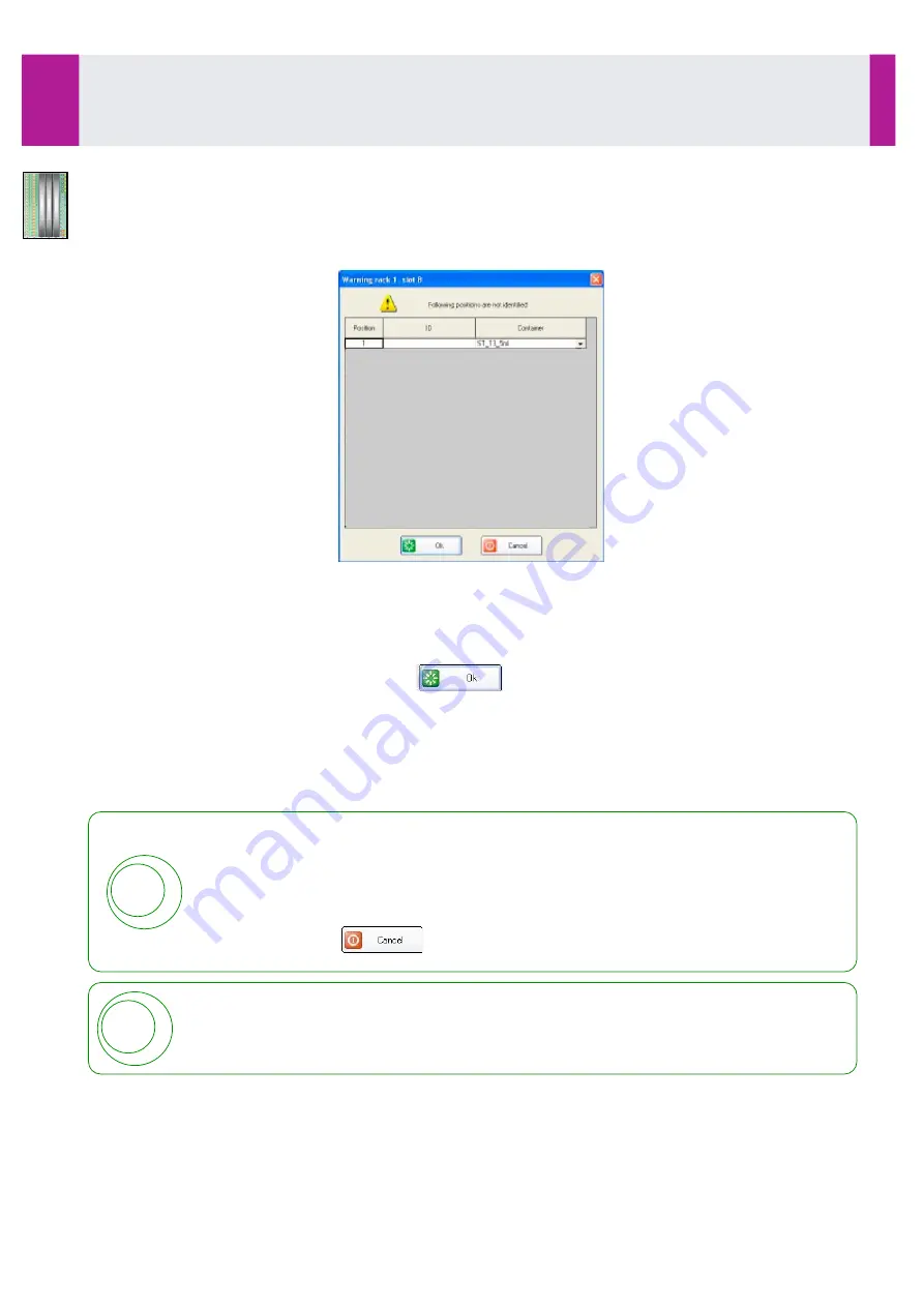
If  the  barcode  identification fails  for  at  least  one  position,  or  if  the  tray  has been  configured,  a  window  is 
displayed with the list of the positions occupied but not identified.
If the tray has been configured from the interface, each position is considered as occupied but not identified. 
This window allows the positions to be identified by programming the identifier and the container type.

Click on the box corresponding to the identifier to program.

Use the keyboard to enter the identifier.

Select the container type from the list.

Use the keyboard to enter the barcode identifier.

Repeat for each position of the list.

When all the positions are identified, click on 

 .

By default, the positions are identified as «specimen» .
A  position  may  be  identified  as  occupied  by  a  calibrator  or  a  control  (see 

3-6-3-  Configure  a  position 

without barcode

, page 65). 

For  tubes from patients whose profile has  already been sent through via a centralised computer or manually 
programmed, the profile in the memory is automatically associated with the position.

If the profile is not in the memory, the profile programming window opens (see Section 3-7, page 69).

When  the  tray  has   been  identified  by  the  barcode  reader,  and  when  the  window  is 
displayed, the tray can be removed  to check identifier(s).
In this case, information can be entered, but can only be validated only after replacing the 
tray in the same position, with a new automatic identification.
Should automatic identification fail, the information will not be saved.

In this case, click on


 .

!

!

For  the  calibrators  and  controls supplied by IDS, enter the  12 figures  from the  barcode: the 
product,  the  lot  number,  the  expiry  date  as well  as the  table  of  corresponding  values  are 
automatically entered.

Use

3-6- L

oading of Calibrators, Controls or Samples in the Sample Compartment (continued)

IDS-iSYS User Manual - Revision M1

Use 3-6


63

Software version V 14

Summary of Contents for IDS-iSYS

Page 1: ...4 For further assistance please contact IDS Technical Support Tel 0191 519 6153 Fax 0191 519 0760 Email techsupport uk idsplc com IDS France 42 rue St phane Mazeau 21320 POUILLY EN AUXOIS FRANCE IDS L...

Page 2: ...res nor the use of the system The manual comprises the following sections and appendices Section 1 Operating Principle Section 2 User Interface Software Section 3 Use Section 4 Messages Section 5 Main...

Page 3: ...ming dilutions page 77 post dilutions carried out on user request Modification in 3 10 1 Result of a calibration page 84 the validation criteria calibrator CV in RLU is modified Modification in 3 10 3...

Page 4: ...ng of the solid waste is now displayed proportional to a maximal capacity of 400 cuvettes Post dilutions can be performed either automatically or on request An automatic maintenance requested by infec...

Page 5: ...the relevant assays must be deselected uncheck the box prior to be selected again Rounding at 0 1 mAbs may be di erent for the same result When two analytes use the same cartridge the number of avail...

Page 6: ...ns for use Caution recommended see Safety Precautions Risk of biological contamination Risk of crushing injury Electrical and electronic waste Dispose of in accordance with current country specific la...

Page 7: ......

Page 8: ...14 1 6 Precautions for Use 15 1 6 1 General precautions 15 1 6 2 Special precautions 16 1 6 3 Safety precautions 16 Section 2 User Interface Software 17 2 1 Structure of the Software 18 2 2 Main Scre...

Page 9: ...a position without barcode 65 3 6 4 End of loading 66 3 6 5 Colour codes associated with sample positions 67 3 6 6 Colour codes associated with removable trays 67 3 6 7 Colour codes associated with po...

Page 10: ...haft 122 5 3 1 3 Cleaning the IDS iSYS D Sorb pump and level sensor shafts 123 5 3 1 4 Cleaning the liquid waste level sensor 123 5 3 1 5 Checking lamp references 124 5 3 1 6 Switch off the instrument...

Page 11: ...stem Configuration 151 7 1 Programming the automatic qualification profile 152 7 2 Creating the reflex tests 153 7 2 1 Creating a new rule 154 7 2 2 Launch option of reflex tests 156 7 2 3 Modifying a...

Page 12: ...ols used on the IDS iSYS Cuvettes cube A 6 A4 2 Storage of the IDS iSYS Cuvette cubes A 6 A 5 Sample barcode symbology managed by the system A 7 A 6 Analyser long stoppage period A 8 A6 1 Less than14...

Page 13: ...SECTION 1 Operating principle...

Page 14: ...11 1 4 3 Connections 11 1 5 Operating principles 12 1 5 1 Luminescence measurements 12 1 5 2 Absorbancy measurements 12 1 5 3 Immunoassays 13 1 5 4 Biochemistry assays 14 1 6 Precautions for Use 15 1...

Page 15: ...oimmunity Biochemistry Substrates Enzymes Electrolytes Specific Proteins The analyser is intended for professional use and must only be used by trained personnel working in compliance with the precaut...

Page 16: ...ried out in disposable cuvettes which are automatically loaded onto a carousel Asynchronous management allows each cuvette to be processed individually and transferred to the relevant reaction modules...

Page 17: ...cy from certain Immunoassay Biochemistry and Turbidimetry reactions 5 A sedimentation module for magnetic particles 6 An automatic cuvette loader holding 960 cuvettes at a time pre formed as a cube 7...

Page 18: ...nalyser up to 15 Immunoassay parameters can be programmed simultaneously or up to 36 Biochemistry parameters or a combination of both up to the maximum number of positions available For Immunoassays t...

Page 19: ...ys trigger reagents are added to produce luminescence For enzymatic assays substrate is added and the photometric changes are measured continuously by the spectrophotometer When measurement is complet...

Page 20: ...etric and enzymatic assays Turbidimetric assays Samples Serum plasma or urine Primary tubes 5 mL 13 x 75 mm 7 mL 13 x 100 mm 10 mL 16 x 75 mm Secondary tubes 13 x 75 mm Cups ref IS CSC105 and ref IS C...

Page 21: ...540 580 and 620 nm Light source Halogen lamp Spectrophotometer with LEDs 12 wavelengths interferential filters 340 405 450 500 540 550 580 620 650 700 720 and 750 nm Light sources multiple LEDs Lumin...

Page 22: ...ws 7 16 GB available hard disk space 32 bit or 20 GB 64 bit Ethernet 2 independent Ethernet network adaptors Ports USB ports min 2 one of which at front Serial port for connection to centralised compu...

Page 23: ...tilated air environment The analyser must be placed on a flat work surface capable of supporting its weight 103 kg without significant vibration The surrounding temperature must be between 15 C and 30...

Page 24: ...Field IDS iSYS System Liquid White All IDS iSYS Wash Solution Blue Immunoassay Liquid Waste Red All IDS iSYS D Sorb Black All AP Substrate Green Immunoassay Depending on the analyser configuration Con...

Page 25: ...h results in the oxidation of the ester into an excited form The return to a stable state is accompanied by the emission of light which is measured and is expressed in relative light units RLU by the...

Page 26: ...generated by detection of the captured complexes is directly proportional to the concentration of analyte in the sample Calculation of results The results are calculated in comparison to a calibratio...

Page 27: ...tinction coe cient of analyte in L mol 1 cm 1 Comment In the set up the factor entered is equal to x 100 The results are calculated either in relation to a calibration or multiplied by a factor The fu...

Page 28: ...tain 400 cuvettes The waste can be emptied during operation It is recommended to empty the solid waste before starting the run cycle Make sure that the reagent and sample racks are clean at all times...

Page 29: ...r than 30 C If necessary provide air conditioning for the site 1 6 2 Special precautions The precautions for use specific to certain handling procedures described throughout the user manual are indica...

Page 30: ...SECTION 2 User Interface Software...

Page 31: ...25 2 3 1 FILE Menu 25 2 3 2 SESSIONS menu 26 2 3 3 DATA menu 27 2 3 4 MAINTENANCE menu 28 2 3 4 MAINTENANCE menu continued 29 2 3 5 SETUP menu 30 2 3 6 MANAGEMENT OF LOTS menu 31 2 3 7 HELP menu 32 2...

Page 32: ...XP or Vista The PC is linked to the analyser via an Ethernet cable The analyser uses embedded software which interprets instructions from the user interface application software into actions to be pe...

Page 33: ...s Reagent Compartment Function buttons Sample Compartment2 Status bar Unlock lid button1 1 Only for analyser equipped with a lid locking system 2 Configurations of Sample compartment Removable trays F...

Page 34: ...of tests remaining Status of the reagent indicated by a colour code see Section 3 page 43 Status of the current calibration see Section 3 page 44 Detailed information for each analyte may be accessed...

Page 35: ...rkload requested including Missing reagents required to perform queued assays Expired reagents Unavailable tests Tests stopped during the cycle due to calibration failures Westgard rules violation etc...

Page 36: ...ing detailed information can be displayed by clicking on the reagent button Identifier and name of the reagent Lot number Number of the container in the lot Type of container Lot expiry date In use st...

Page 37: ...and the planned workload will be modified a green contour colour indicates that all the tests programmed for the sample are completed It is possible to configure the software in LOCAL SYSTEM SETTINGS...

Page 38: ...shes blue in normal activity COM fixed when there is a break in communication the connection activity with the centralised computer system LIS flashes blue in normal activity LIS fixed when there is a...

Page 39: ...Stored results The database is saved under the format used in the application Allows the user to restore all or part of the saved database as desired including Analytical configuration Personal libra...

Page 40: ...vailable volumes and the number of tests for each on board reagent before or during the run cycle Programming and processing of tests for the reagent Cartridge Check System CCS Simplifies programming...

Page 41: ...on of the control results with selected rules History by product record of the results obtained for each reagent and for all tests using this reagent Printouts global printouts of Levey Jennings data...

Page 42: ...les are cleaned by aspirating IDS iSYS D SORB solution The relevant volume is pipetted by the sampling needle and distributed into four cuvettes The cuvettes are transferred to the washer module After...

Page 43: ...s Support allows the user to deactivate a washer module or a specific wavelength in case of failure Displays the analyser status see Section 2 2 page 21 User Interface Software 2 3 Menus continued IDS...

Page 44: ...an unlimited number of profiles which can be used for programming For removable tray configuration Allows the operator to define for each removable rack the type of rack M mixed for samples calibrato...

Page 45: ...n the system Allows users to manually input the values for each lot of calibrator Allows activation of the calibrator lots used for a specific assay Lists controls used on the system Allows users to e...

Page 46: ...LP menu Displays information concerning software for example specific version User Interface Software 2 3 Menus continued IDS iSYS User Manual Revision M1 User Interface Software 2 3 32 Software versi...

Page 47: ...options from the main screen F2 Work list F3 Start the run cycle F4 Storage F5 Calibrations F6 Run cycle monitoring F8 Status of analyser F9 Stop run cycle User Interface Software 2 4 Functions keys...

Page 48: ...SECTION 3 Use...

Page 49: ...nfigure a position without barcode 65 3 6 4 End of loading 66 3 6 5 Colour codes associated with sample positions 67 3 6 6 Colour codes associated with removable trays 67 3 6 7 Colour codes associated...

Page 50: ...the lid can not accidentally fall down Analysers without locking system The lid can be opened directly The sensors on the analyser will detect that he lid has been opened and prevent any movement of...

Page 51: ...to the piston rod until the clips is fully inserted Closing the lid Hold the lid in upper position using its handle Remove the lid support tool Gently lower the lid until closing Use Information on th...

Page 52: ...cting Start up from the session menu All modules are initialised and the ancillary reagents are automatically primed If a new version of the software is detected on the analyser after opening a messag...

Page 53: ...the drawer light flashes red and green When opening the reagent compartment during the run cycle assays which are under way may be stopped if a reagent was scheduled to be added when the compartment w...

Page 54: ...re supplied in the form of individual reagent bottles Biochemistry reagent racks are designed to contain either 6 x 20 mL bottles or 3 x 50 mL bottles Rack 3 x 50 ml Rack 6 x 20 ml If the reagents hav...

Page 55: ...sequence until use begins automatically Each time a cartridge or a reagent bottle already stabilized on board is removed then installed again in the compartment a countdown before use begins even for...

Page 56: ...the barcode identifier To select another type of rack click on Rack Then select the type of rack installed 3 x 50 mL for Biochemistry reagents 6 x 20 mL for Biochemistry reagents 3 x 50 ml rack 6 x 20...

Page 57: ...is stopped and a new countdown begins A countdown may be stopped in certain clearly identified cases e g quick unloading of a reagent previously on board Click on the relevant cartridge or reagent In...

Page 58: ...ation is displayed by clicking on the relevant reagent Immunoassay cartridges Deadline for using the cartridge on the system Date is replaced by expiry time when the day of expiry date begins Countdow...

Page 59: ...he format Days Hours Minutes Seconds All this information can be displayed by clicking on the position occupied by the reagent and is stored in the menu MANAGEMENT OF LOTS REAGENTS The two following s...

Page 60: ...expiry date The on board expiry date in days and hours is initially calculated from the first installation date of the reagent and from the on board stability supplied with the lot data The expiry tim...

Page 61: ...ot expiry date The expiry time is set at 23 59 for all ancillary reagents A message displayed in the WARNING window the last day of use for a consumable indicates that expiry will occur later that day...

Page 62: ...ner Scan the ancillary with the barcode reader The analyser will beep for the first time Within 10 seconds install the new bottle in its position identified by colour code Install the supply line into...

Page 63: ...gent for the IDS iSYS D Sorb and IDS iSYS Wash solutions The analyser will beep a second time Replace the lid and the plunger of the IDS iSYS System Liquid Priming of the IDS iSYS System Liquid takes...

Page 64: ...arcode is not read by the barcode reader click on the ancillary reagent then use the keyboard to enter the identifier Once a new bottle is installed a message is displayed Click on to confirm the prim...

Page 65: ...into the loader with the window to the front Remove the protective plastic strip pull forwards to break the seal Gently pull upwards to remove the protective strip Place the protective strip over the...

Page 66: ...plates will cause the analyser to jam Correct positioning of the cube of cuvettes in the loader is essential for the automatic cuvette loading module to function correctly The cuvettes are disposable...

Page 67: ...rt of the automatic start up of the analyser see Section 7 7 1 Programming the automatic qualification profile page 152 3 4 1 Programming the qualification profile From the main screen select The qual...

Page 68: ...On the Text Import screen click on OK In the OpenO ce Scalc worksheet highlight line 1 to line 18 results for CCS Many important data are not visible on the screen as some columns in the file are not...

Page 69: ...nel Do not perform immunoassays if the analyser performance level is not satisfactory valid Refer to Section 6 of this manual Troubleshooting see Section 6 page 143 Complete the form with the laborato...

Page 70: ...5 1 Programming calibrations Accepting an automatic action Automatic requests for calibration are generated only for the reagent lots on board either when a new lot of a Biochemistry reagent is detect...

Page 71: ...Programming a Calibration of a New Reagent Lot When calibrating a new Immunoassay reagent lot the calibrators associated with this lot must be placed into the sample rack before programming the reque...

Page 72: ...ow shows a list of all tests in the personal library It also includes the date and time of the last calibration for the on board analytes Click on the box in the column in front of the lot to be calib...

Page 73: ...tic request controls are run in the number of replicates defined in the assay setup Accepting an automatic action Automatic requests for controls are generated for each level and only for reagent lots...

Page 74: ...of a control level not validating the calibration and managed in frequency the number of replicates can be selected for each run From the main screen click on To request a QC1 QC2 QC3 or QC4 quality c...

Page 75: ...hed in order to maintain the performance of the analyser Any position of the sample compartment may be used to install samples calibrators and controls Each of these have an associated icon shown in t...

Page 76: ...is inserted in the rail the positions and the barcoded tubes are automatically identified by the integrated barcode reader On the interface the tray is displayed with the free and occupied positions...

Page 77: ...in at its position with its barcode label facing inwards Once the removable tray is installed into the compartment this sample must be identified using the keyboard Configure a tray Click on the tray...

Page 78: ...gure a position without barcode page 65 For tubes from patients whose profile has already been sent through via a centralised computer or manually programmed the profile in the memory is automatically...

Page 79: ...in a free position on the rack If the association process is correct the analyser will beep On the interface the display will indicate that the position has been identified For tubes from patients who...

Page 80: ...ier 1 to 32 alphanumeric characters Select type of product as Sample and click on For samples whose profiles have already been programmed or sent through via a centralised computer the profile in the...

Page 81: ...n menu any new assays waiting to be carried out are added to the analyser s workload For the others the new assays will be added to the analyser s workload after clicking on the corresponding button F...

Page 82: ...a calibrator no associated request Position occupied by a control no associated request 3 6 6 Colour codes associated with removable trays Rail free Tray not used by the analyser Tray detected but no...

Page 83: ...a predictive list of assays This list is established according to test priority and according to the order of the sample tray positions As the tests have not yet been sent to the analyser the sample...

Page 84: ...asma Urine Other Serum Plasma must be selected for each blood sample whether collected in a dry tube serum or collected in a tube containing anticoagulants plasma Urine must be used only when defined...

Page 85: ...on board tray will be carried out whether or not defined for automatic start 3 8 1 Performing assays Assays are carried out in the following order Calibrations Controls Emergency STAT samples Samples...

Page 86: ...ompartment The trays defined for automatic start are automatically added to the analyser s workload For the others the new assays will be added to the analyser s workload after clicking on the corresp...

Page 87: ...t into the compartment the lag time before use is automatically managed by the system The reagents must be stabilised at the temperature of the refrigerated compartment before use Magnetic particles i...

Page 88: ...he fault then click on If the fault cannot be resolved during the assay the software displays a message Release this message then either wait for the end of the current workload or request all assays...

Page 89: ...rinsing the arm stops at the position where the fault is detected Click on A message confirming the request displays To stop the cycle click on If assays are under way the analyser finishes these befo...

Page 90: ...ay is managed The tray can be removed when all the positions have been completed The option indicating the end of sampling does not take into account the dilution if applicable when a result is outsid...

Page 91: ...for each of the reflex tests associated to this analyte Only a calculated result of a patient profile can generate reflex tests A result of a reflex test with message RFX will not generate reflex test...

Page 92: ...lytical configuration a post dilution can be performed either automatically or after accepting an automatic une action or programming from the profile edition Option Post dilution is automatically per...

Page 93: ...or which a dilution must be performed The post dilution is requested by selecting Then click on Programming in the worklist Click on then select the relevant result Click on The post dilution is reque...

Page 94: ...ly identified by the integrated barcode reader as the tray is inserted in the rail On the interface the tray is displayed with the free and occupied positions Each identified position is labelled with...

Page 95: ...e calculated but at least one of the results has an attention message Calibrators Controls Samples a lack of reagent sample or another fault prevents the requested assays being carried out in full Onl...

Page 96: ...for each control associated with the calibration QC1 for Biochemistry QC1 to QC4 for Immunoassay is also given If the calibration is validated the message OK is displayed In the event of an invalid ca...

Page 97: ...lidating a Calibration Calculated percentage of translation is lower than the programmed limit Immunoassay Percentage of the deviation on calibrator signal RLU is within acceptable limits provided by...

Page 98: ...pted at the discretion of the user Accepting a calibration without modification In this case click on the button The control s is are calculated Any forcing of a calibration is recorded in the journal...

Page 99: ...are calculated with the new curve equation When points have been excluded the icon is displayed with the calibration date When the recalculated calibration is valid with the control s within acceptab...

Page 100: ...Yes Yes No No No No No 22s The violation of certain rules will generate automatic requests In this event the icon flashes in the WARNING button The violation of 2 2S 4 1S 10 X rules will automaticall...

Page 101: ...measurement the message OMR is accompanied by High limit of the sample measurement range Limits are expressed in working units Comment When the message ORA accompanies the messages OMR or OMR the resu...

Page 102: ...k on To print out all the results of the work list select Print results and click on Programming reflex tests Select the relevant profile Double click on the line to display the profile Click on to pr...

Page 103: ...corresponding CV Results are displayed in the order of positions in the sample compartment Other sorting criteria may be selected for the display by using one of the following options The selected op...

Page 104: ...l configuration If the ASU message accompanies the message RED one of the absorbances is still outside the limits of reaction defined after dilution In this case the sample must be re diluted to a lev...

Page 105: ...case the sample must be tested again is displayed instead of the result MES Luminescence Error when recovering the measurements Spectrophotometry Error when recovering the measurements or the result c...

Page 106: ...alue given takes into account the dilution factor RFX Result obtained for a reflex test RT Storage temperature of reagents outside limits during the assay SUB Spectrophotometry Detection of enzymatic...

Page 107: ...d thresholds POS The result is positive above the defined threshold The result is positive above the defined threshold The result is positive above the defined threshold The result is positive above t...

Page 108: ...selection profiles without message then click The incomplete profiles can be stored when the analyser is not carrying out an assay This option automatically removes the analysis requests remaining in...

Page 109: ...red to analyser software s database When using the options Selection or All results always verify that the relevant profiles have been stored prior to remove them display the work list in standard mod...

Page 110: ...e examination The results and the statistical calculations can be displayed for a selected period of time 60 days maximum including mean standard deviation CV and charts control results plotted around...

Page 111: ...be selected in the relevant dropdown list Select the period of time required for display then click on The results of the control are displayed for the selected time period Use 3 13 Quality Control Ma...

Page 112: ...rol Another lot can be selected in the relevant dropdown list Select the time period of interest then click on Then select the test in the relevant dropdown list Use 3 13 Quality Control Management co...

Page 113: ...clicking on the tab 3 13 2 Westgard rules The Westgard rules are selected for each test in the QUALITY CONTROL tab of the analytical configuration with an application of 1 or 2 levels of control In t...

Page 114: ...ontrol levels one measurement exceeds the 2s limit and the other exceeds the 2s limit The run is judged to be OUT OF CONTROL 4 1s 4 consecutive control measurements within or across a run exceeds the...

Page 115: ...empty the drip tray if necessary Empty the solid waste tray see 3 14 1 Emptying the solid waste page 101 and the liquid waste if necessary see 3 14 2 Emptying the liquid waste page 102 Waste must be d...

Page 116: ...5 5 5 1 Decontaminating the containers of solid and liquid wastes page 147 With disposable solid waste container Remove the disposable container from the solid waste tray Discard the disposable solid...

Page 117: ...te the liquid waste container see Section 5 5 5 1 Decontaminating the containers of solid and liquid wastes page 147 Replace the level sensor in the empty waste container Then release the solid waste...

Page 118: ...n the left hand side of the analyser into position 0 In order to maintain the performance of the operating system the computer must be turned o one time per week When the analyser has been inactive fo...

Page 119: ...SECTION 4 Messages...

Page 120: ...d with Calibrations 105 4 2 Messages Associated with Calibration Controls 107 4 3 Messages Associated with Results 108 4 4 Warning Messages 112 4 5 Error Messages 113 Section 4 IDS iSYS User Manual Re...

Page 121: ...ide the limits specified in the analytical configuration of the test Fail of calibration calculation All fields The calibration could not be calculated Sensitivity out of range Biochemistry The sensit...

Page 122: ...for one assay Biochemistry The slope of the kinetics calculated for one of the calibrators was calculated on a non linear section of the curve No control for checking All fields The control measureme...

Page 123: ...ontrol are displayed with the calibration curve in the control section Message Meaning Failed calibration Biochemistry Immunoassay The control was not calculated as the calibration is invalid Failed r...

Page 124: ...side the limits of reaction defined after dilution In this case the sample must be re diluted to a level higher than that programmed in the analytical configuration then tested again BLR Biochemistry...

Page 125: ...sted again is displayed instead of the result MES Luminescence Error when recovering the measurements Spectrophotometry Error when recovering the measurements or the result can not be calculated becau...

Page 126: ...given takes into account the dilution factor RFX Result obtained for a reflex test RT Storage temperature of reagents outside limits during the assay SUB Spectrophotometry Detection of enzymatic hyper...

Page 127: ...resholds POS The result is positive above the defined threshold The result is positive above the defined threshold The result is positive above the defined threshold The result is positive above the d...

Page 128: ...icking If the user does not want to accept these actions it is possible to cancel the request by clicking This action will be detailed in the Records Daily weekly or monthly maintenance has not been c...

Page 129: ...way to complete or ask for the run cycle to be stopped The fault must be released again after stopping the run cycle At the time of release the element concerned is automatically initialised Errors i...

Page 130: ...SECTION 5 Maintenance...

Page 131: ...124 5 3 2 Immunoassay Maintenance 124 5 3 2 1 Cleaning the IDS iSYS Wash Solution pump and level sensor shafts 124 5 3 2 2 Rinsing of the AP Substrate tubing 125 5 4 Analyser Interventions 126 5 4 1...

Page 132: ...ning and closing The lid must always be fully open and the lid support tool must always be installed Take care not to knock the lid during any analyser intervention When the lid is not fully open ther...

Page 133: ...analyser are in contact with biological samples There is therefore a potential risk of infection Wear disposable gloves for all handling procedures Do not use any spray products on the analyser Open...

Page 134: ...ess of the needle Remove the lid support tool and close the lid see page 36 Handle the probe with care Do not twist or bend the probe during cleaning 5 1 1 4 Decontamination of the probe This maintena...

Page 135: ...y during opening and closing The lid must always be fully open and the lid support tool must always be installed Take care not to knock the lid during any analyser intervention When the lid is not ful...

Page 136: ...ose the lid see page 36 When maintenance is complete click on the corresponding then confirm the maintenance by clicking on YES 5 2 1 2 Cleaning the sample tray and Plexiglas WARNING RISK OF BIOLOGICA...

Page 137: ...rt the lid support tool see pages 35 and 36 Pour alcohol at 70 v v ethyl or isopropyl into the rinsing well Use a cotton bud soaked in alcohol at 70 v v ethyl or isopropyl to clean the well When maint...

Page 138: ...any error the date and time are recorded This procedure can be carried out with the lid opened When this maintenance is completed proceed to the weekly shutdown of the computer From the File menu clic...

Page 139: ...e two clips at either side and gently pulling ensuring the tubes remain connected Clean the pump shaft with absorbent paper soaked in alcohol at 70 v v ethyl or isopropyl Return the pump body to its s...

Page 140: ...ips at either side and gently pulling ensuring the tubes remain connected Clean the pump shaft with a cloth soaked in alcohol at 70 v v ethyl or isopropyl Return the pump body to its shaft Put the cov...

Page 141: ...afts Remove the cover located on the right hand side of the analyser Click on the corresponding button in front of this item in this maintenance list No spindle must rotate operate while this maintena...

Page 142: ...AP Substrate bottle with the de ionised water bottle Click on When the rinsing is complete the following message displays Remove the de ionised water bottle and replace the original AP Substrate bott...

Page 143: ...onnect the lamp from its supply Unscrew the securing screws located on both sides of the lamp in order to remove the lamp support unit Remove the old lamp WARNING RISK OF BURNS Do not touch the lamp w...

Page 144: ...ort tool see pages 35 and 36 When the lid of the analyser is equipped with a locking system the sampling arm moved to its home position Install the specific protective tray under the probe Unscrew the...

Page 145: ...analyser Switch the analyser o and unplug the power cable Using a screwdriver remove the fuse holder from its housing Replace the faulty fuse ensuring it is of the same value and the same type time d...

Page 146: ...flat head screwdriver Insert a flat head screwdriver into the fuse holder and turn anti clockwise to unscrew Take out the fuse holder and replace the faulty fuse with one of the same value and the sa...

Page 147: ...the pump with absorbent paper soaked in alcohol at 70 v v ethyl or isopropyl Put the pump back in place on its shaft Replace the cover of the analyser Switch the analyser back on again and perform th...

Page 148: ...sopropyl Put the pump back in place on its shaft Replace the cover Remove the lid support tool and close the lid see page 36 Carry out partial priming of the arm in order to prime the circuit again 5...

Page 149: ...s procedure only at the request of IDS Technical Service Support personnel Depending on whether the locking system is present or not the procedure is di erent The operations to be performed in each ca...

Page 150: ...e installed Take care not to knock the lid during any analyser intervention When the lid is not fully open there is a risk of it falling During closing maintain the lid open when removing the lid supp...

Page 151: ...e lid and insert the lid support tool see pages 35 and 36 Gently touch the probe the probe must slightly resist to the lateral movement WARNING RISK OF BIOLOGICAL CONTAMINATION The probe is in contact...

Page 152: ...etting arm will move to the rinsing well A message confirming completion of the procedure is displayed Click on to validate this message A window containing the settings values is displayed Click on T...

Page 153: ...ing arm will move to the rinsing well A message confirming cancellation of the procedure is displayed Click on to validate this message The main position adjustment window is displayed 5 4 10 2 Adjust...

Page 154: ...a particular use of the analyser without user s protection against the pipetting arm movements The pipetting arm will move with the lid opened Contact with the moving pipetting arm may cause severe in...

Page 155: ...ft Right Forward Backward The probe must be centered on the pin of the target Then adjust the Z position click on the Down 1 mm button twice Adjust the probe position using repeatedly the Down 0 1 mm...

Page 156: ...to the rinsing well A message confirming completion of the procedure is displayed Click on to validate this message The message displays Remove the activation key The removal is detected by the analy...

Page 157: ...active in two windows Clicking on this button will cancel changes in the position adjustment and the current adjustment will be kept To keep the previous adjustment Click on The pipetting arm will mo...

Page 158: ...pen the lid and insert the lid support tool see pages 35 and 36 If the lid of the analyser is equipped with a locking system the sampling arm moves to its home position Install the specific protective...

Page 159: ...probe by screwing it in by hand as far as possible to avoid risk of leakage Remove the protective tray Remove the lid support tool and close the lid see page 36 When the analyser is not in cycle mode...

Page 160: ...the washers or a particular wavelength of the spectrophotometer the relevant element can be temporarily deactivated using the SYSTEM CONFIGURATION menu This should only be used when following guidance...

Page 161: ...sher deselection may impair the Immunoassay analytical throughput Deactivate a wavelength To deactivate a wavelength uncheck the relevant box to deselect the wavelength Then click on When the modifica...

Page 162: ...su cient volumes From the MAINTENANCE menu select REPEAT AN AUTOMATIC MAINTENANCE then select As soon as the menu option is selected the maintenance is carried out by the system When maintenance is c...

Page 163: ...e of the lid Open the lid and insert the lid support tool see pages 35 and 36 Switch o the analyser Decontaminate the internal side of the lid with a disinfectant wipe solution suitable for medical de...

Page 164: ...le for medical devices Rinse it with water then decontaminate again with a disinfectant solution suitable for medical devices Dry the tray prior to replacing in its compartment Liquid waste container...

Page 165: ...SECTION 6 Problems Corrective Action...

Page 166: ...Problems Corrective Action 148 6 1 Resolving Errors in Cartridge Check System CCS 149 Section 6 IDS iSYS User Manual Revision M1 148 Software version V 14...

Page 167: ...of bubbles in the reagents there should be none 3 Check that the probe is not blocked or bent Carry out a decontamination of the probe see Section 5 1 1 4 page 117 if applicable If the probe is bent r...

Page 168: ...t a full priming of the arm 2 Check for the presence of bubbles in the reagents there should be none 3 Check that the probe is not blocked or bent Carry out a decontamination of the probe see Section...

Page 169: ...SECTION 7 System Configuration...

Page 170: ...tion of reflex tests 156 7 2 3 Modifying an existing rule 157 7 2 4 Importing exporting rules 157 7 2 5 Removing a rule 157 7 3 Configuring the print settings 158 7 4 Options of validating and transfe...

Page 171: ...The fields for programming the qualification profile are displayed From the drop down list select the necessary test and programme the required number of replicates see CCS IFU and click Repeat the op...

Page 172: ...le mode These tests can be created or imported from a file The existing reflex tests can be displayed by any level of access even during a run cycle Tests to launch when the defined conditions are met...

Page 173: ...ondition and the programmed value lower lower or equal higher higher or equal by clicking the appropriate radio button Click on The rule is created with its number in the list and is immediately appli...

Page 174: ...a reference Then click on Click in the cell of the Test to launch column The tests of the personal library are displayed Select the additional test s to launch by clicking in the relevant box Then cl...

Page 175: ...profile after accepting the automatic action or by using a specific button in the profile edition Tests are automatically added to the profile Tests are added to the profile after user s indication Ti...

Page 176: ...an then be imported into the software interface Exporting the rules Click on Select the assigned folder and enter the file name Click on SAVE Importing the rules Click on Select the source file file f...

Page 177: ...er the header text To insert a line break use CTRL ENTER Select the desired printing options by clicking the appropriate radio button Select the printer if necessary Exit the menu by clicking on to sa...

Page 178: ...sults are validated as soon as available the result is validated and sent to the centralised computer The completed profile is automatically stored Results without messages are validated only the resu...

Page 179: ...dependent on user level Certain menus can be not accessible for certain levels or can only be displayed but cannot be modified Adding new users is allowed from the Supervisor level Each user is define...

Page 180: ...ord and its cases combination of characters in capital and lower cases Then select in the list the level of access Click on to record the new user Modify a user Select the user to modified then click...

Page 181: ...CD by indicating the relevant pathway When the update starts a window is displayed with the list of the modified analytes and with the result of each modification In case of error message or failure w...

Page 182: ...Appendices...

Page 183: ...ist of symbols used on the IDS iSYS Cuvettes cube A 6 A4 2 Storage of the IDS iSYS Cuvette cubes A 6 A 5 Sample barcode symbology managed by the system A 7 A 6 Analyser long stoppage period A 8 A6 1 L...

Page 184: ...ccordance with current local regulations Except when an automated system of liquid waste treatment is used liquid waste must be processed prior to disposal in order to eliminate a biological risk This...

Page 185: ...ssential for this declaration to accompany the analyser during any transportation e g return to factory Cleaning decontamination process Decontaminate the probe with a wipe soaked in a decontaminating...

Page 186: ...RESS This analyser was cleaned and decontaminated on I declare that I have carried out all stages of cleaning and disinfecting described in the user manual NAME Position optional SIGNATURE LABORATORY...

Page 187: ...ith solid waste must be disinfected Solid and liquid waste as well as liquid waste tubing must be disposed of according to the current local laws In the event of resale to a third party the first OWNE...

Page 188: ...re Quantity A4 2 Storage of the IDS iSYS Cuvettes cube Always store IDS iSYS Cuvettes cube in their original packaging Never store IDS iSYS Cuvettes cube outside the original packaging Always store th...

Page 189: ...yes yes Codabar no yes yes EAN UPC yes no no Recommendations The barcode should contain at least 5 digits for the removable rack configuration sample tubes identified by the barcode reader integrated...

Page 190: ...dic circuit pump and may have an impact on CCS results A6 1 Less than 14 days The analyser is placed in standby mode with a daily automatic wake up Ancillary reagents are kept on board except AP Subst...

Page 191: ...nce by clicking on Repeat this procedure a second time After the two rinsing procedures are completed perform the Rinsing of the AP Substrate tubing maintenance for a third time to compete the rinse a...

Page 192: ...ithout exception days Program a daily automatic shut down without exception days One hour time delay between wake up and shut down is required If necessary unselect the automatic QC profile option Cli...

Page 193: ...nance a third time for rinsing and emptying the fluidic circuits Replace the two Trigger bottles by two 250 mL bottles containing distilled water When the first step of the maintenance is completed re...

Page 194: ...th current local regulations see APPENDIX I Waste disposal page A2 WARNING RISK OF BIOLOGICAL CONTAMINATION Waste which contains or has been in contact with biological specimens must be considered to...

Page 195: ...e installed a message proposing an automatic priming is displayed Click on to confirm the priming of the product s The analyser starts the priming sequence Request twice ALL SYSTEM FULL PRIMING from t...

Page 196: ...ntact IDS Technical Support Tel 0191 519 6153 Fax 0191 519 0760 Email techsupport uk idsplc com IDS France 42 rue St phane Mazeau 21320 POUILLY EN AUXOIS FRANCE IDS Ltd 10 Didcot Way Boldon Business P...

Page 197: ...ection setup 17 3 ASTM Compatible V2 Version 19 3 1 General information 19 3 2 The Header Block 21 3 3 The Patient Block 22 3 4 The Test Order Block 24 3 5 The Result Block 27 3 6 The Comment Block 29...

Page 198: ...ication Line 54 4 10 1 Equipment configuration 54 4 10 2 Change to connection setup 54 4 10 3 Transferring quality control results 56 5 Examples of Data Transfer 57 6 Examples of Data Transfer 58 6 1...

Page 199: ...sion o ers additional functionalities for the transfers to the LIS transfer of the traceability associated with a result transfer of messages associated with a result in a Comment block transfer of qu...

Page 200: ...lways preceded by a Test Order block or by another Result block If several results are sent through for one test there will then be several Result blocks following a Test Order block typically if a te...

Page 201: ...n ASTM message H _ IDS iSYS B300B0378 P 2 20111124135800 P 1 20105863 BONTEMPS Robert 19500226 M DUPONT Comment Radiology O 1 01 7148345 25OHD R A S O R 1 25OHD 25 2 ng mL 10 0 to 100 0 N F 2011112413...

Page 202: ...cape delimiter _ which indicates an escape sequence for dealing with special characters N B The record delimiter is fixed and is always the character ASCII 13 carriage return Message Control ID Not us...

Page 203: ...e Assigned Patient ID Not used Laboratory Assigned Patient ID 20105863 PID Patient ID Not used Patient Name BONTEMPS Robert Field consisting of 5 components last name first name initials su x and titl...

Page 204: ...Not used Practice Field 1 Not used Practice Field 2 Not used Admission and Discharge Dates Not used Admission Status Not used Location Not used Nature of Alternative Diagnostic Code Not used Alternat...

Page 205: ...Primary Tube ST for Secondary Tube For correct functioning of the apparatus it is important to allocate the correct type of container used for the sample If this component is null the default containe...

Page 206: ...ume Not used Collector ID Not used Action Code A Action to be carried out on the block test or tests This field may contain the values A for Add C for Cancel N for New P for Pending Q for QC For the d...

Page 207: ...System Not used Instrument Section ID Not used Report Type O This field may take the values O Order C Correction P Preliminary results F Final results X Cancel I Instrument pending in response to a re...

Page 208: ...he unique IDS iSYS identifier of the analyte Data or Measurement Value 25 2 The value in the form of ASCII chain Results which cannot be calculated are sent in the format Each character is separated b...

Page 209: ...take the following values C Correction P Preliminary results F Final results X Request not honored I Results pending S Partial results Date of change in Instrument Normative Values Not used Operator I...

Page 210: ...the PID optional and the SID obligatory allowing the profile quoted to be identified Ending Range ID Number Not used Universal Test ID ALL This field can either indicate 1 particular test in the ident...

Page 211: ...direction IDS iSYS to LIS A is used when the LIS does not respond to a request In such cases the request is cancelled this field takes the value A The request is transmitted 3 times after which the t...

Page 212: ...1 Always at 1 as there is only one sequence per message Termination code N This code designates of end of the message with the following values depending on the situation N Normal T Abandon issuer R...

Page 213: ...32C link DB9 standard pinouts TCP IP link Ethernet cable RJ45 8 pins 2 8 2 Change to connection setup The connection set up for the interface can be found under SET UP SETTINGS LOCAL SYSTEM With RS232...

Page 214: ...this container type until the sample is processed by the analyser blue colour code Configurable options continued Active for the option Clot Detection When a clot is detected in a sample results from...

Page 215: ...ock typically if a test has been carried out on several analytes the result of each of these will be provided in one single message but in several Result blocks The Manufacturer Information block this...

Page 216: ...OHD R A S O R 1 25OHD 04 F 1 63 9 ng mL 10 0 to 100 0 N F 20111123171733 IDS iSYS B300B0378 C 1 I FOR MRE N M 1 25OHD 04 F 1 51 25OHD 0952 209525602987 20120229 System Liquid 72634 00162 20121209 Cuve...

Page 217: ...delimiter _ which indicates an escape sequence for dealing with special characters N B The record delimiter is fixed and is always the character ASCII 13 carriage return Message Control ID Not used Ac...

Page 218: ...D 20105863 PID Patient ID Not used Patient Name BONTEMPS Robert Field consisting of 5 components last name first name initials su x and title Only the first 2 fields are used When sending a control fr...

Page 219: ...ile Patient Active Medication Not used Patient Diet Not used Practice Field 1 Not used Practice Field 2 Not used Admission and Discharge Dates Not used Admission Status Not used Location Not used Natu...

Page 220: ...cate the correct type of container used for the sample If this component is null the default container type defined for the tray will be used The SID of the profile concerned by the request Instrument...

Page 221: ...Not used Collector ID Not used Action Code A Action to be carried out on the block test or tests This field may contain the values A for Add C for Cancel N for New P for Pending Q for QC For the devi...

Page 222: ...tem Not used Instrument Section ID Not used Report Type O This field may take the values O Order C Correction P Preliminary results F Final results X Cancel I Instrument pending in response to a reque...

Page 223: ...t type 02 for a control 04 for a patient Result type F for final P for partial Replicate number 1 2 up to 10 Control identifier defined as follow 21 for a control Level 1 22 for a control Level 2 23 f...

Page 224: ...S Sex R Race And is able to provide an indication about the bases on which the values of normality were determined Result Status F This field forces to F or P replicate on the IDS iSYS can take the fo...

Page 225: ...for each comment block in the message Comment Source I Issuer can take the following values P Practice L computer system in the direction LIS I Instrument Comment Text FOR MRE If the field Comment Typ...

Page 226: ...versal test ID name NULL Universal test ID type NULL Manufacturer s code Test type 02 for a control 04 for a patient Result type always F for final Depending on the test a final result can be a mean v...

Page 227: ...this option is not checked this field consists of NaOH Lot Bottle Number Expiry date H2O2 Lot Bottle Number Expiry date Wash S Lot Bottle Number Expiry date Wash1 Number of the washer Wash2 Number of...

Page 228: ...PID optional and the SID obligatory allowing the profile quoted to be identified Ending Range ID Number Not used Universal Test ID ALL This field can either indicate 1 particular test in the identifi...

Page 229: ...rection IDS iSYS to LIS A is used when the LIS does not respond to a request In such cases the request is cancelled this field takes the value A The request is transmitted 3 times after which the tran...

Page 230: ...Always at 1 as there is only one sequence per message Termination code N This code designates of end of the message with the following values depending on the situation N Normal T Abandon issuer R Aba...

Page 231: ...32C link DB9 standard pinouts TCP IP link Ethernet cable RJ45 8 pins 3 10 2 Change to connection setup The connection set up for the interface can be found under SET UP SETTINGS SYSTEM With RS232C sel...

Page 232: ...e analyser blue colour code The sample container sent by the LIS is ignored and is set with the container type defined for the removable rack or for the fixed tray The user can modify this container t...

Page 233: ...nding to the traceability of AP SUBSTRATE and washer s used in the pretreatment step The relevant field is described in page 31 The field Specific ancillaries in the Manufacturer block will contain th...

Page 234: ...ock typically if a test has been carried out on several analytes the result of each of these will be provided in one single message but in several Result blocks The Manufacturer Information block this...

Page 235: ...HD R A S O R 1 25OHD 04 F 1 63 9 ng mL 10 0 to 100 0 N F 20111123171733 IDS iSYS B300B0378 C 1 I FOR MRE N M 1 25OHD 04 F 1 51 25OHD 0952 209525602987 20120229 System Liquid 72634 00162 20121209 Cuvet...

Page 236: ...delimiter _ which indicates an escape sequence for dealing with special characters N B The record delimiter is fixed and is always the character ASCII 13 carriage return Message Control ID Not used Ac...

Page 237: ...tient ID 20105863 PID Patient ID Not used Patient Name BONTEMPS Robert Field consisting of 5 components last name first name initials su x and title Only the first 2 fields are used When sending a con...

Page 238: ...Practice Field 1 Not used Practice Field 2 Not used Admission and Discharge Dates Not used Admission Status Not used Location Not used Nature of Alternative Diagnostic Code Not used Alternative Diagno...

Page 239: ...cate the correct type of container used for the sample If this component is null the default container type defined for the tray will be used The SID of the profile concerned by the request Instrument...

Page 240: ...Not used Collector ID Not used Action Code A Action to be carried out on the block test or tests This field may contain the values A for Add C for Cancel N for New P for Pending Q for QC For the devi...

Page 241: ...tem Not used Instrument Section ID Not used Report Type O This field may take the values O Order C Correction P Preliminary results F Final results X Cancel I Instrument pending in response to a reque...

Page 242: ...yte Test type 02 for a control 04 for a patient Result type F for final P for partial Replicate number 1 2 up to 10 Control identifier defined as follow 21 for a control Level 1 22 for a control Level...

Page 243: ...S iSYS can take the following values C Correction P Preliminary results F Final results X Request not honored I Results pending S Partial results Date of change in Instrument Normative Values Not used...

Page 244: ...for each comment block in the message Comment Source I Issuer can take the following values P Practice L computer system in the direction LIS I Instrument Comment Text FOR MRE If the field Comment Typ...

Page 245: ...versal test ID name NULL Universal test ID type NULL Manufacturer s code Test type 02 for a control 04 for a patient Result type always F for final Depending on the test a final result can be a mean v...

Page 246: ...322 20121104 Wash1 2 Wash 2 Wash3 DSORB If the field Assay type takes the value 51 this field consists of NaOH Lot Bottle Number Expiry date H2O2 Lot Bottle Number Expiry date Wash S Lot Bottle Number...

Page 247: ...PID optional and the SID obligatory allowing the profile quoted to be identified Ending Range ID Number Not used Universal Test ID ALL This field can either indicate 1 particular test in the identifi...

Page 248: ...rection IDS iSYS to LIS A is used when the LIS does not respond to a request In such cases the request is cancelled this field takes the value A The request is transmitted 3 times after which the tran...

Page 249: ...Always at 1 as there is only one sequence per message Termination code N This code designates of end of the message with the following values depending on the situation N Normal T Abandon issuer R Aba...

Page 250: ...32C link DB9 standard pinouts TCP IP link Ethernet cable RJ45 8 pins 4 10 2 Change to connection setup The connection set up for the interface can be found under SET UP SETTINGS SYSTEM With RS232C sel...

Page 251: ...e analyser blue colour code The sample container sent by the LIS is ignored and is set with the container type defined for the removable rack or for the fixed tray The user can modify this container t...

Page 252: ...uality control results select the corresponding option in the tab under SET UP SETTINGS SYSTEM menu 4 ASTM Compatible V3 Version 4 10 Line of Communication continued IDS iSYS Connection Protocol Revis...

Page 253: ...t of assay identifiers The list of assay identifiers is obtained in the SET UP PERSONAL LIBRARY menu The list of assay identifiers can also be printed 9 Line of Communication The list of assay identif...

Page 254: ...12 2011 15 46 40 2P 1 20105863 BONTEMPS Robert 19500226 M DUPONT Comment Radiology CR ETX 4D CR LF 05 12 2011 15 46 40 ACK 05 12 2011 15 46 40 STX 05 12 2011 15 46 40 3O 1 01 7148344 25OHD R A S Q CR...

Page 255: ...5 20 ENQ 05 12 2011 11 25 20 ACK 05 12 2011 11 25 20 STX 05 12 2011 11 25 20 1H IDS iSYS Simulator 2 D 1 20111205112519 CR ETX 1F CR LF 05 12 2011 11 25 20 ACK 05 12 2011 11 25 20 STX 05 12 2011 11 25...

Page 256: ...1 2011 10 22 16 4L 1 N CR ETX 07 CR LF 23 11 2011 10 22 16 ACK 23 11 2011 10 22 16 STX 23 11 2011 10 22 16 5H IDS iSYS Simulator 2 D 1 20111123102214 CR ETX 19 CR LF 23 11 2011 10 22 16 ACK 23 11 2011...

Page 257: ...37 26 ACK 24 11 2011 13 37 26 STX 3O 1 7148345 25OHD R S CR ETX 78 CR LF 24 11 2011 13 37 26 ACK 24 11 2011 13 37 27 STX 4R 1 25OHD 25 2 ng mL 10 0 to 100 0 N F 20111124133726 IDS iSYS B300B0378 CR ET...

Page 258: ...0 0 to 100 0 N F 20111123152310 IDS iSYS B300B0378 CR ETX 7D CR LF 23 11 2011 15 23 11 ACK 23 11 2011 15 23 11 STX 5M 1 25OHD 04 F 1 51 25OHD 0952 209525602987 20120229 System Liquid 72634 00162 20121...

Page 259: ...245 00049 20130203 TRIGA 70244 00200 20130203 Wash S 72508 00322 20121104 Wash1 3 Wash2 Wash3 DSORB CR ETX 46 CR LF 05 12 2011 12 02 50 ACK 05 12 2011 12 02 50 STX 7R 2 25OHD 04 F 2 5 0 ng mL F 201111...

Page 260: ...STX 6h1 3 Wash2 Wash3 DSORB CR ETX 89 CR LF 23 11 2011 11 59 55 ACK 23 11 2011 11 59 55 STX 7P 2 25DCTL1 02 CR ETX B2 CR LF 23 11 2011 11 59 55 ACK 23 11 2011 11 59 55 STX 0O 1 207284703325 25OHD 02...

Page 261: ...30 39 STX 07 05 2015 15 30 39 1H IDS iSYS Simulator 2 D 1 20150507153038 CR ETX 28 CR LF 07 05 2015 15 30 39 ACK 07 05 2015 15 30 39 STX 07 05 2015 15 30 39 2P 1 007 FRANCKY JEAN 19900107 U WHO TANNER...

Page 262: ...07 05 2015 15 53 04 ACK 07 05 2015 15 53 04 STX 4R 1 00000 04 F 1 0 03 mDO 0 75 to 1 15 N F SYSTEM SYSTEM 20150507155304 IDS iSYS0000000001 CR ETX 57 CR LF 07 05 2015 15 53 04 ACK 07 05 2015 15 53 04...

Page 263: ...if the last component s takes a NULL value the last component delimiter s can be not sent The exchanges between IDS iSYS and LIS can be recorded by selecting the option available in the tab under SET...

Reviews: