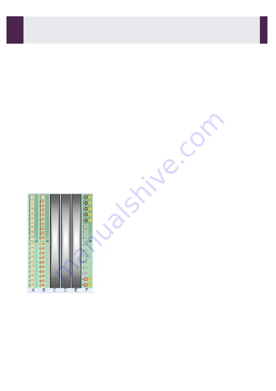
Sample compartment
The illustration of the sample compartment depends on the analyser configuration. For the two
configurations (fixed sample tray or removable trays), the occupied positions are shown.
Each position can be occupied by:
•
Calibrators.
•
Controls.
•
Samples.
•
Stat.
An icon identifies the type of sample installed in a position (see Section 3, page 67).
For each occupied position the following options are available:
•
Entry of the identifier and the type of product installed (without a barcode).
•
Programming of the sample analyses to be carried out.
•
Results display for controls or samples.
A colour coded analysis status is associated with the center of the position (see Section 3, page 80).
A colour code is associated to the contour of the positions, to inform whether the system is using the installed
product (see Section 3, page 68). During a run cycle:
•
a blue contour colour indicates that the installed product is scheduled in the workload and can still be
removed; remove this product and the planned workload will be modified.
•
a green contour colour indicates that all the tests programmed for the sample are completed. It is
possible to configure the software in
LOCAL SYSTEM SETTINGS
menu to change the contour colour at
the end of sampling rather than completion of assays. The same colour code is applied on each tray for
the removable-tray configuration.
Removable trays
The illustration to the left shows the sample
compartment with the on-board trays
The tray and its samples are identified by the integrated
barcode reader when loading the tray in the
compartment.
Each tray is numbered.
For each tray, the free and occupied positions are
displayed. Each position can be occupied by :
•
calibrators,
•
controls,
•
samples
The positions occupied but not identified by barcode
reading are programmed after loading the tray in the
sample compartment.
Any position of a 20 position-tray may be used to load a
calibrator, a sample or a stat sample.
A colour code is associated with the removable-tray
configuration (see Section 3, page 67).
User Interface Software
2-2-
Main Screen (continued)
IDS-iSYS User Manual - Revision M1
User Interface Software 2-2
23
Software version V 14
Summary of Contents for IDS-iSYS
Page 7: ......
Page 13: ...SECTION 1 Operating principle...
Page 30: ...SECTION 2 User Interface Software...
Page 48: ...SECTION 3 Use...
Page 119: ...SECTION 4 Messages...
Page 130: ...SECTION 5 Maintenance...
Page 165: ...SECTION 6 Problems Corrective Action...
Page 169: ...SECTION 7 System Configuration...
Page 182: ...Appendices...


