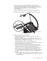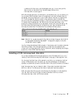
10.
Install
a
heat
sink
on
the
microprocessor:
a.
Remove
the
plastic
protective
cover
from
the
bottom
of
the
heat
sink,
if
one
is
present.
Attention:
1)
Do
not
set
down
the
heat
sink
after
you
remove
the
plastic
cover.
2)
Do
not
touch
the
thermal
grease
on
the
bottom
of
the
heat
sink.
Touching
the
thermal
grease
will
contaminate
it.
If
the
thermal
grease
becomes
contaminated,
contact
your
service
technician.
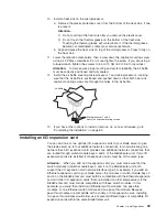
b.
Align
and
place
the
heat
sink
on
top
of
the
microprocessor.
Press
firmly
on
the
heat
sink.
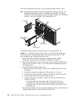
11.
Lower
the
retention
mechanism;
then,
screw
down
the
captive
mounting
screw
using
a
#2
Pillips
screwdriver.
Do
not
over-tighten
the
screw.
If
you
are
using
a
torque
wrench,
tighten
the
screws
to
8,5
to
13
Nm
(6.3
to
9.6
foot-pounds).
Attention:
To
help
ensure
proper
cooling
and
system
reliability
the
air
baffle
must
be
correctly
positioned
and
fully
seated.
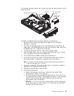
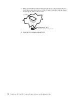
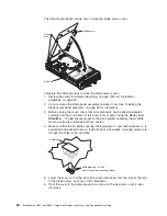
12.
Install
the
air
baffle
covering
microprocessor
1
and
microprocessor
4,
making
sure
that
the
air
baffle
is
positioned
and
pushed
down
so
that
both
heat
sink
captive
mounting
screws
are
through
the
holes
in
the
air
baffle.
Air baffle
Microprocessor 1 and 4
heat sink captive mounting screws
13.
If
you
have
other
options
to
install
or
remove,
do
so
now;
otherwise,
go
to
“Completing
the
installation”
on
page
62.
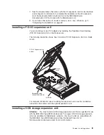
Installing
an
I/O
expansion
card
You
can
add
one
or
two
optional
I/O
expansion
cards
to
your
blade
server
to
give
the
blade
server
up
to
four
additional
network
connections
for
communicating
on
a
network.
Each
I/O
expansion
card
provides
two
additional
network
connections
that
are
routed
through
switch-module
bays
3
and
4
of
the
BladeCenter
unit.
If
two
I/O
expansion
cards
are
installed,
both
expansion
cards
must
be
of
the
same
type.
Attention:
When
you
add
an
I/O
expansion
card,
you
must
make
sure
that
the
switch
modules
in
switch-module
bays
3
and
4
on
the
BladeCenter
unit
both
support
the
I/O
expansion
card
network-interface
type.
For
example,
if
you
add
an
Ethernet
expansion
card
to
your
blade
server,
the
modules
in
switch-module
bays
3
and
4
on
the
BladeCenter
unit
must
both
be
compatible
with
the
Ethernet
expansion
card.
All
other
I/O
expansion
cards
that
are
installed
on
other
blade
servers
in
the
BladeCenter
unit
must
also
be
compatible
with
these
switch
modules.
In
this
example,
you
could
then
install
two
Ethernet
switch
modules,
two
pass-thru
modules,
or
one
Ethernet
switch
module
and
one
pass-thru
module.
Because
pass-thru
modules
are
compatible
with
a
variety
of
I/O
expansion
cards,
installing
two
pass-thru
modules
would
allow
use
of
several
different
types
of
compatible
I/O
expansion
cards
within
the
same
BladeCenter
unit.
Chapter
4.
Installing
options
49
Summary of Contents for HS40 - BladeCenter - 8839
Page 1: ...BladeCenter HS40 Type 8839 Hardware Maintenance Manual and Troubleshooting Guide ERserver...
Page 2: ......
Page 3: ...BladeCenter HS40 Type 8839 Hardware Maintenance Manual and Troubleshooting Guide ERserver...
Page 6: ...iv BladeCenter HS40 Type 8839 Hardware Maintenance Manual and Troubleshooting Guide...
Page 10: ...viii BladeCenter HS40 Type 8839 Hardware Maintenance Manual and Troubleshooting Guide...
Page 20: ...10 BladeCenter HS40 Type 8839 Hardware Maintenance Manual and Troubleshooting Guide...
Page 30: ...20 BladeCenter HS40 Type 8839 Hardware Maintenance Manual and Troubleshooting Guide...
Page 42: ...32 BladeCenter HS40 Type 8839 Hardware Maintenance Manual and Troubleshooting Guide...
Page 86: ...76 BladeCenter HS40 Type 8839 Hardware Maintenance Manual and Troubleshooting Guide...
Page 114: ...104 BladeCenter HS40 Type 8839 Hardware Maintenance Manual and Troubleshooting Guide...
Page 131: ...Appendix B Safety information 121...
Page 132: ...122 BladeCenter HS40 Type 8839 Hardware Maintenance Manual and Troubleshooting Guide...
Page 133: ...Appendix B Safety information 123...
Page 134: ...124 BladeCenter HS40 Type 8839 Hardware Maintenance Manual and Troubleshooting Guide...
Page 135: ...Appendix B Safety information 125...
Page 136: ...126 BladeCenter HS40 Type 8839 Hardware Maintenance Manual and Troubleshooting Guide...
Page 137: ...Appendix B Safety information 127...
Page 149: ...Appendix B Safety information 139...
Page 150: ...140 BladeCenter HS40 Type 8839 Hardware Maintenance Manual and Troubleshooting Guide...
Page 151: ...Appendix B Safety information 141...
Page 152: ...142 BladeCenter HS40 Type 8839 Hardware Maintenance Manual and Troubleshooting Guide...
Page 153: ...Appendix B Safety information 143...
Page 154: ...144 BladeCenter HS40 Type 8839 Hardware Maintenance Manual and Troubleshooting Guide...
Page 166: ...156 BladeCenter HS40 Type 8839 Hardware Maintenance Manual and Troubleshooting Guide...
Page 171: ......
Page 172: ...Part Number 25K8105 Printed in USA 1P P N 25K8105...

