157
Part 1 Specification
[1] Write position table data
An example of writing the target position, positioning band and speed data one by one to the position table under No.
10 corresponding to positioner mode axis (0) is explained.
•
Target position
100 mm
→
10000 = 2710H
•
Positioning band
0.3 mm
→
30 = 001EH
•
Speed
2 mm/sec
→
200
=
00C8H
z
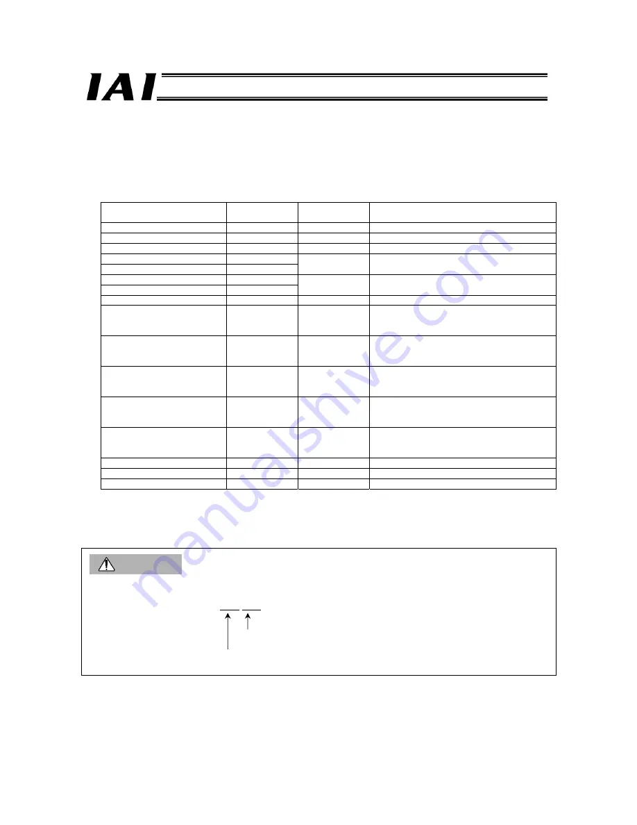
Target Position Write Query
Field name
RTU mode data
(8 bits)
Data length
(bytes)
Remarks
Header None
-
Slave address
3F H
1
Fixed.
Function code
10 H
1
Starting address
(upper)
F6 H
Starting address
(lower)
02 H
2
Initial request command register address of axis
(0)
Number of registers
(upper)
00 H
Number of registers
(lower)
05 H
2
The number of registers is 5.
Bytes
0A H
1
Number of registers x 2 = 10 (0AH)
New data 1
(upper)
10 H
New data 1
(lower)
00 H
1 each for upper
and lower words
2
Request command (position write)
New data 2
(upper)
00 H
New data 2
(lower)
0A H
1 each for upper
and lower words
2
Data 0: Position No. 10 is specified.
New data 3
(upper)
27 H
New data 3
(lower)
10 H
1 each for upper
and lower words
2
Data 1: Lower word of target position data
New data 4
(upper)
00 H
New data 4
(upper)
00 H
1 each for upper
and lower words
2
Data 2: Upper word of target position data
New data 5
(upper)
00 H
New data 5
(upper)
00 H
1 each for upper
and lower words
2
Data 3: An axis number is specified (axis 0).
Error check
(CRC)
16 bits
2
Based on calculation result (6891)
Trailer None
-
Total bytes
19
Sent Query:
3F10F60200050A1000000A27100000
00006891
Received Response: 3F10F6020005969C
Caution
Each gateway command must be cleared after use. If the command area is not cleared, the next command cannot be
accepted.
Query sent in this example: 3F 06 F602 0000 1F5C
Request command clear code
Request command area address
Summary of Contents for RoboNet
Page 1: ...Operation Manual Forth Edition ROBONET ...
Page 257: ...237 Part 2 Startup Chapter X Installed face down X Installed face up ...
Page 354: ...334 ...
Page 395: ...375 ...
Page 396: ...376 ...
Page 397: ...377 ...


