background image


106 

Part 1  Specification


*  Set an appropriate time so that “T1 

 0 ms” is satisfied, by considering the scan time of the host controller. 


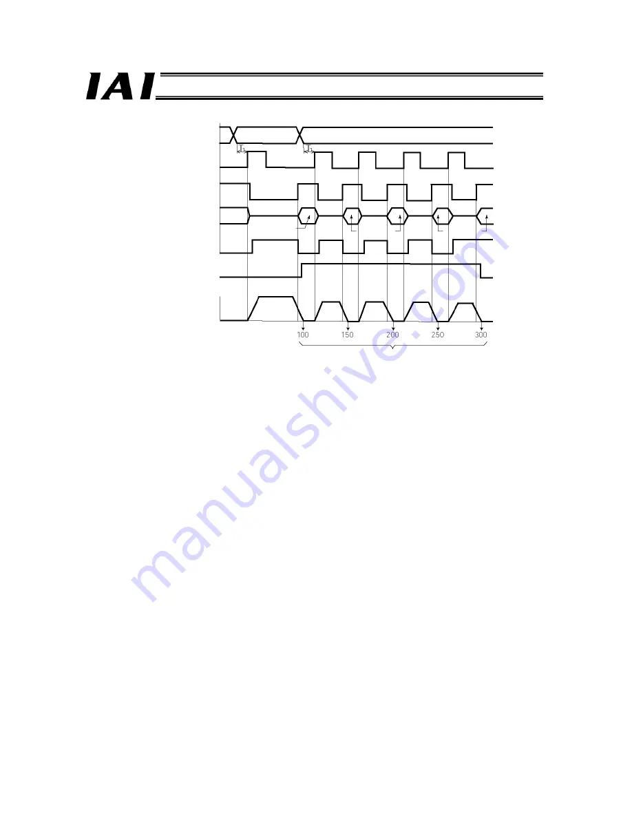
[Explanation of Operation]   

[1]  Positioning operation to position 1 (100.00 mm) is performed.   
[2]  Upon completion of positioning to position 1, the position complete signal (PEND) turns “1” (ON). The zone signal 

(PZONE) also turns “1” (ON).   
The position number is changed from 1 to 2, and the start signal (CSTR) is turned “1” (ON).   

[3]  Once the actuator starts moving, the position complete signal (PEND) changes from “1” (ON) to “0” (OFF) and 

the moving signal (MOVE) changes from “0” (OFF) to “1” (ON). Turn the start signal (CSTR) “0” (OFF) after 
confirming that the PEND has turned “0” (OFF). 

[4]  After the actuator has moved by 50 mm, the position complete signal (PEND) turns “1” (ON) and the moving 

signal (MOVE) turns “0” (OFF) again. At this time, the PLC registers the first count in the movement counter.   
Next, the start signal (CSTR) is turned “1” (ON) to start the next 50-mm movement.   

[5]  Steps [3] and [4] are repeated hereafter.   


The PLC checks the status of the zone signal (PZONE) upon completion of positioning. If the signal is “0” (OFF), the PLC 
determines that this is the last load.   
If the count in the PLC does not match the zone signal status, the signal timings may not be synchronized. 

[1]

[2]

[3]

[4]

[5]

Command position 

Start  

(CSTR)


Position complete 

(PEND) 

Moving (MOVE)

Actuator movement

Completed position

Speed

Position 1 

Position 2 

Position 1 

Position 2 

Position 2 

Zone signal 

(PZONE) 

Distances from home


Time


Summary of Contents for RoboNet

Page 1: ...Operation Manual Forth Edition ROBONET ...

Page 2: ...ical Standard for Industrial Machinery If a single class2 power supply unit is insufficient to provide enough power use multiple class2 power supply units At that time follow the example below for the wiring layout Also 0 V line to each power supply is required to be common Simple absolute R unit Simple absolute R unit Simple absolute R unit R unit unit unit unit unit unit Power Supply Power Suppl...

Page 3: ...odel RCB TU SIO A B One e CON connector one junction and one terminal resistor are supplied with one controller link cable e CON connector 3 1473562 4 by AMP Junction 5 1473574 4 by AMP GateWay R unit Terminal resistor Controller link cable Model CB RCB CTL002 24 V power supply Notes on Connecting PC and Teaching Pendant to ROBONET Whose 24 V Power Supply Is Grounded at Positive Terminal If the po...

Page 4: ...ot be connected directly to the GateWayR unit If a teaching pendant or PC is connected directly to the GateWayR unit the power supply may be short circuited causing the PC or teaching pendant to suffer damage Cannot be connected directly PC GateWay R unit This teaching pendant cannot be used 24 V power supply ...

Page 5: ...ides the information you need to know to use the ROBONET Before using your ROBONET peruse this manual and understand its contents fully Unauthorized reproduction of this manual whether in part or in whole is strictly prohibited The information provided in this manual is subject to change without notice for the sake of improvement This manual has been created with the utmost attention to accuracy S...

Page 6: ...nger leading to death or serious injury Danger Warning Failure to observe the instruction may result in death or serious injury Warning Caution Failure to observe the instruction may result in injury or property damage Caution Note The user should take heed of this information to ensure the proper use of the product although failure to do so will not result in injury Note Also note that this produ...

Page 7: ... has qualifications for crane operation and sling work z When using a crane or equivalent equipments make sure not to hang a load that weighs more than the equipment s limit z Use a hook that suits for the load Consider the safety factor of the hook in such factors as shear strength z Do not get on the load that is hanged on a crane z Do not leave a load hanged up with a crane z Do not stand under...

Page 8: ... z Implement measures to prevent the loads etc from dropping due to a power outage or emergency stop z Ensure safety by wearing protective gloves protective goggles and or safety shoes as necessary z Do not insert fingers and objects into openings in the product Doing so may result in injury electric shock product damage fire etc 5 Teaching z Whenever possible perform teaching from outside the saf...

Page 9: ...rator should carry a handy emergency stop switch so that the operation can be stopped any time when an abnormality occurs z When working inside the safety fences appoint a safety watcher in addition to the operator so that the operation can be stopped any time when an abnormality occurs The safety watcher must also make sure the switches are not operated inadvertently by a third party z Put up a s...

Page 10: ...eripherals and ensure compliance of these models with the related standards under the EMC Directives 2 Applicable Standards Low voltage Directive EN50178 Electronic equipment used in electrical installations EMC Directives EN55011 Radio interference characteristics of industrial scientific and medical equipment generating radio frequency EN61000 6 2 Immunity in industrial environment EN61000 4 2 I...

Page 11: ...A device in which additional safety measures are taken against electric shock without depending solely on the basic insulation by connecting conductors that may become contactable should the basic insulation fail to a protective grounding conductor of a fixed cable of the facility In other words a protection class I device refers to a device for which grounding connection is required ...

Page 12: ...control panel constructed to shut off water oil carbon dust etc IP54 2 Power supply A Use the ROBONET in an environment of overvoltage category II as specified in IEC 60664 1 Accordingly be sure to install a circuit breaker between the power distribution board and ROBONET controller B For the 24 VDC power supply use a SELV power supply bearing a CE Mark with reinforced insulation of inputs outputs...

Page 13: ...tely near the cable connectors on the controller unit One clamp filter is required for each gateway unit and two for each controller unit On the field network cable install each clamp filter by looping it twice around the cable Manufacturer TDK Corp Model ZCAT3035 1330 External View of Clamp Filter Shape dimensions mm Shape dimensions ZCAT type ...

Page 14: ...facturer Okaya Electric Model ZCAT3035 1330 External View of Surge Protector 7 Cables Take note that cables are also subject to various limitations A All cables connected to the ROBONET such as the motor cable encoder cable and various network cables must be less than 30 m long B For the CC Link cable use a dedicated Version 1 10 cable terminal resistance 110 Ω BWZ series ...

Page 15: ...sed on the science or technology available when the product was shipped from IAI 5 Problem resulting from an act of God natural disaster accident or any other event beyond the control of IAI 6 Natural fading of paint or other deterioration normally expected over time 7 Wear of consumable parts due to use 8 Noise and other perceptive phenomena that do not affect the function of the facility The war...

Page 16: ...M PM 01 Operation Manual Not sold in the US market Manual revision history 1 August 2008 First edition Integration of the ROBONET Operation Manual Specification ROBONET Operation Manual Startup Maintenance and operation manual of the ROBONET extension unit 2 February 2009 Second edition Addition of UL standards application page 3 March 2009 Third edition Change in Gateway Parameter Setting Tool ...

Page 17: ...ternal Dimensions 19 3 5 1 Name of Each Part 19 3 5 2 LED Indicators 20 3 5 3 MODE Switch 22 3 5 4 TP Connector 22 3 5 5 User Setting Switches 22 3 5 6 ROBONET Communication Connector 22 3 5 7 Power supply Input Terminal Block 22 3 5 8 FG Terminal Frame Ground 23 3 5 9 EMG Connector Emergency Stop 23 3 5 10 Field Network Connector 25 3 5 11 External Dimensions 29 3 6 Operation Function List 30 3 7...

Page 18: ...ators 184 4 3 3 Brake Release Switch 186 4 3 4 User Setting Switches 186 4 3 5 Axis Number Setting Switch 186 4 3 6 ROBONET Communication Connector 187 4 3 7 Simple Absolute R Unit Connector 187 4 3 8 Power supply Input Terminal Block 187 4 3 9 Motor Cable Connector 189 4 3 10 Encoder Cable Connector 190 4 3 11 External Dimensions 191 4 4 Parameters 192 4 4 1 Parameter List 192 4 4 2 Parameters Re...

Page 19: ...ositive Terminal of 24 V Power Supply 262 Chapter 3 Controller Address Setting 263 Chapter 4 Absolute Reset 264 4 1 Overview of Simple Absolute System 264 4 2 Setting the Configuration Switches 265 4 3 Connecting the Backup Battery 267 4 4 Setting the Parameters 267 4 5 Performing an Absolute Reset 267 4 5 1 Performing an Absolute Reset in the PC Software 267 4 5 2 Performing an Absolute Reset fro...

Page 20: ...Indicator Statuses Corresponding to Representative Alarms 348 1 3 Alarms of the Controller Unit and Simple Absolute R Unit 349 1 3 1 Overview of Alarms 349 1 3 2 Alarms Causes and Actions 352 1 3 3 Messages Displayed during Operation Using the Teaching Pendant or PC Software 360 Chapter2 Maintenance Inspection 362 2 1 Periodic Inspection Items 363 2 2 Important Information on Unit Replacement 364 ...

Page 21: ...N units RAC RCA2 RCL controllers and RPCON unit RCP2 RCP3 controllers Up to 16 axes can be controlled in one ROBONET system You can also configure an absolute system by connecting a simple absolute R unit to the controller of each axis The GateWayR unit is available in four types DeviceNet type CC Link type PROFIBUS type and RS485 SIO type The ROBONET is treated as a slave station in a field netwo...

Page 22: ...ion circuit boards which substantially reduces the hassle of wiring 4 Easy Installation All units are installed on a DIN rail 35 mm so installation to a control panel or equipment is easy Units can also be installed side by side with other components 5 Simple Absolute System The axis drive unit is either a RPCON unit for 24 V pulse motor actuators or RACON unit for 24 V servo motor actuators Altho...

Page 23: ... and electrical current cannot be monitored If an alarm occurs however a corresponding simple alarm code will be output to the completed position number area so you can monitor simple alarm codes in this area 3 Direct numerical specification mode In this mode the actuator is operated by specifying the position data speed acceleration deceleration positioning band and push current limiting value di...

Page 24: ...Position table Direct specification Position table Position table Completed position number monitor X Zone output monitor Position zone output monitor X Teaching operation X X X Jogging operation X Inching operation X Various status signal monitor 1 X Current position monitor 1 X Alarm code monitor 1 X Speed electrical current monitor 1 X X X X Axis monitor function in AUTO mode 2 Handshake X Posi...

Page 25: ...cupied area information The ROBONET occupied area information set on the master side can be checked 6 Operation of parameter files Setting of the positioner 2 mode setting of reserved axes and operation of parameter files are supported when the version of the parameter setting tool is 1 0 3 0 or later and the firmware version of the GateWayR unit is 000B or later Settings of the Solenoid valve mod...

Page 26: ...s Also the ROBONET extension unit can be used to implement a ROBONET system of multiple row layout multi stage layout and connect non ROBONET controller units SCON PCON CF ERC2 to a ROBONET system via external SIO link A ROBONET system configuration is shown on the next page 2 2 List of Component Units The units comprising a ROBONET system are listed below Product name Model DeviceNet specificatio...

Page 27: ...le absolute R unit RPCON unit Simple absolute R unit Simple absolute connection circuit board Terminal resistor circuit board ROBONET communication connection circuit board Power supply connection plates RACON unit RPCON unit Emergency stop circuit RCA RCL actuators RCP actuator RCA RCL actuators RCP actuator RCA RCL actuators RCP actuator ROBONET Configuration 1 Basic ...

Page 28: ... board Power supply connection plates Extension unit RACON unit RPCON unit Extension unit Unit link cable Multi stage layout Controller connection cable External SIO link 4 way junction 4 way junction Terminal resistor Axis 0 Axis 1 Axis 2 Axis 3 Axis 4 Axis 5 Axis 6 Axis 7 Field network DeviceNet CC Link PROFIBUS RS485 SIO ROBONET Configuration 2 Multi stage layout and external SIO link ...

Page 29: ... cable when the ROBONET communication connection circuit board simple absolute connection circuit board or ROBONET extension unit is used multi stage layout or external SIO link Installation method Installation on a DIN rail 35 mm However controllers corresponding to external SIO link axes are excluded 2 4 24 V Power Current Consumption of Each Unit Current consumption GateWayR unit 600 mA max Com...

Page 30: ...on in the case that a remote sensing function is equipped Reference 1 It is recommended that the ROBONET power be turned on off on the AC power supply side primary side of the 24 V power supply If the ROBONET power is turned on off on the output side of the 24 V power supply the large current will flow for a brief moment when the power is turned on as explained in 2 Turning on the power on the AC ...

Page 31: ... a simple absolute R unit 24 V power supply Terminal block Emergency stop circuit RPCON encoder cable port RACON encoder cable CB ACS PA GateWayR unit Field network connector PG white Simple absolute R unit PG red Motor cable CB RCP2 MA RPCON encoder cable CB RCP2 PA Motor cable CB ACS MA RACON encoder cable port Simple absolute R unit not connected ...

Page 32: ...ed ROBO Cylinders The GateWayR unit is available in four types to support field networks of CC Link DeviceNet PROFIBUS and RS485 SIO communication types A total of up to 16 axes can be connected by combining dedicated ROBONET controller units RACON RPCON and non ROBONET controller units SCON PCON CF ERC2 and each axis can be monitored in the AUTO mode only when the touch panel display RCM PM 01 is...

Page 33: ... 08ABGYAU by Phoenix Contact DeviceNet communication connector MSTB2 5 5 ST 5 08ABGYAU by Phoenix Contact RS485 SIO communication connector MC1 5 4 ST 3 5 by Phoenix Contact None Terminal resistors 110 Ω 130 Ω 1 2 W None None None 1 2 3 Main unit EMG connector Terminal resistor circuit board Common accessories Dedicated accessories for CC Link type Communication connector terminal resistors Dedica...

Page 34: ...n 2 00 Its specifications vary depending on the extended cyclic setting This product supports the following functions of CC Link Version 2 00 Extended cyclic transmission Relaxed limitation on station link cable length CC Link Version 1 10 is also supported as long as the extended cyclic transmission setting of x1 four stations occupied can be used ...

Page 35: ...th type 2 wire method corresponding to EIA RS485 Baud rate 230 4k bps Error control method CRC with no parity bit 2 Communication cable ROBONET communication connection circuit board supplied ROBONET extension cable when an extension unit is used SIO communication specification Number of connectable units 16 axes max Surrounding air temperature 0 to 40 C Surrounding humidity 95 RH max non condensi...

Page 36: ...ype 2 wire method corresponding to EIA RS485 Baud rate 230 4k bps Error control method CRC with no parity bit 2 Communication cable ROBONET communication connection circuit board supplied ROBONET extension cable when an extension unit is used SIO communication specification Number of connectable units 16 axes max Surrounding air temperature 0 to 40 C Surrounding humidity 95 RH max non condensing S...

Page 37: ... circuit board supplied ROBONET extension cable when an extension unit is used SIO communication specification Number of connectable units 16 axes max Surrounding air temperature 0 to 40 C Surrounding humidity 95 RH max non condensing Surrounding environment Free from corrosive gases flammable gases oil mist or powder dust Storage temperature 25 to 70 C Storage humidity 95 RH max non condensing Vi...

Page 38: ...ations Cable length 100 m max master RGW SIO Transmission path configuration IAI s dedicated multi drop differential communication Communication method Half duplex Synchronization method Start stop method Transmission path format Conforming to EIA RS485 2 wire type Baud rate 230 4 k bps Error control method No parity bit CRC 2 Communication cable ROBONET communication connection circuit board supp...

Page 39: ... same except for the field network connector provided on top of the unit 3 5 1 Name of Each Part Front cover open User setting switches ROBONET communication connector Power supply input terminal block MODE switch LED indicators Field network connector Varies according to the network type EMG connector FG terminal TP connector ...

Page 40: ...rding to the field network type as shown in the table below 1 CC Link Name Indicator color Status Explanation Steady An error CRC error station number setting error or baud rate setting error is present STATUS 1 Orange Blinking The station number or baud rate has changed from the set value due to a reset STATUS 0 Green Steady A refresh polling command has been received successfully or a refresh co...

Page 41: ...An error parameter error or PROFIBUS configuration error is present Steady Initialization has completed Green Blinking Initialization has completed diagnosis event has occurred STATUS 0 Orange Steady An error exceptional error is present 4 RS485SIO Name Indicator color Status Explanation STATUS 1 Green Steady Sending data STATUS 0 Green Steady Receiving data ...

Page 42: ... SW3 Always OFF SW2 Always OFF Endian 2 ON SIO through mode OFF Modbus gateway mode SW1 When this switch is set to ON the TP enable switch signal is effective 1 SW1 to SW4 are ON when set to the right side and OFF when set to the left side 2 Remote I O endian ON Little endian LSB first PLC by Mitsubishi Omron etc OFF Big endian MSB first PLC by Siemens 3 5 6 ROBONET Communication Connector This co...

Page 43: ...F the drive sources of all axes simultaneously Gateway end connector MC1 5 2 GF 3 81 by Phoenix Contact Cable end connector MC1 5 2 STF 3 81 by Phoenix Contact Standard accessory Signal name Explanation EMG Emergency stop switch EMG Emergency stop switch RACON unit Simple absolute R unit RPCON unit ROBONET communication connection circuit boards Power supply connection plates Interconnections of R...

Page 44: ...the emergency stop can be reset using the emergency stop reset switch If an emergency stop is actuated with a teaching pendant however the emergency switch will be reset when the same emergency switch is turned and reset EMG connector TP connector Teaching pendant GateWayR unit Axis controller unit Axis controller unit ROBONET Communication Connector TP connection detection circuit Drive source cu...

Page 45: ...e ground This signal is internally connected to SLD and the enclosure The cable end connector terminal resistor 110 Ω 1 2 W and terminal resistor 130 Ω 1 2 W are supplied A terminal resistor must be connected to the units at both ends of the CC Link system If the RGW CC is a terminal unit of the CC Link system connect the supplied terminal resistor between the DA and DB pins of the connector The a...

Page 46: ...onnector Item Description Applicable wire size Stranded wire AWG24 to 12 0 2 to 2 5 mm 2 Cable stripping length 7 mm stripping length of cable sheath Although the RGW DV does not come with terminal resistors a terminal resistor must be connected to both ends of the main DeviceNet line Use a T branch tap with terminal resistor 121 Ω 1 1 4 W or terminal block type terminal resistor 121 Ω 1 1 4 W at ...

Page 47: ... to the enclosure Caution 1 The mating cable end connector D sub 9 pin connector is not supplied 2 The RGW PR does not have terminal resistor setting switches If the RGW PR is connected at the end of a network connect a terminal resistor to the network connector or use a connector with terminal resistor as specified below z Connecting a terminal resistor z PROFIBUS connector with terminal resistor...

Page 48: ...communication connector Signal name Explanation SA Communication line A SB Communication line B Built in terminal resistor 220 Ω conforming to RS485 SG Signal ground FG Frame ground This signal is connected to the enclosure Applicable Wire for Cable end Connector Item Description Applicable wire size Stranded wire AWG28 to 16 0 14 to 1 5 mm 2 Cable stripping length 7 mm ...

Page 49: ...29 Part 1 Specification 3 5 11 External Dimensions Installable on a 35 mm DIN rail 50 from DIN rail center 69 3 from DIN rail surface ...

Page 50: ...n the position table separately U Set acceleration and deceleration in the position table separately Push operation U Set in the position table U Set in the position table Speed change during movement U Combine two or more position numbers U Combine two or more position numbers Pause O Solenoid valve mode 1 X Solenoid valve mode 2 Zone signal Set using the position table and user parameters Output...

Page 51: ...oning is started change the acceleration deceleration data while the actuator is moving and restart the operation in order to decelerate the actuator at a value different from the acceleration U Set in the position table Specify the push current limiting value 8 bit integer and also specify the push direction DIR and push mode PUSH U Combine two or more position numbers Since the speed data is acc...

Page 52: ... Data 0 Data 0 Data 1 Data 1 Data 2 Data 2 Data 3 Data 3 Command area Cannot be used 6 Cannot be used 6 In the direct numerical specification mode the command area cannot be used but this area is occupied as part of the data area 2 Data Area Configuration in the Positioner Mode and Simple Direct Mode PLC output Axis input Axis output PLC input Upper byte Lower byte Number of words Positioner mode ...

Page 53: ...indicates the upper word of 2 word data 4 Data Area Configuration in the Position 2 Mode Solenoid valve mode 1 And Solenoid Valve 2 Mode Upper byte Lower byte Number of words Upper byte Lower byte Number of words Position specification area Command position number 1 Completed position number 1 Control signal area Control signal 1 Status signal 1 3 7 1 Examples of Overall Address Configuration Over...

Page 54: ...ition data specification L RWr 0CH Axis 3 Current position data L RWw 0DH Axis 3 Position data specification H RWr 0DH Axis 3 Current position data H RWw 0EH Axis 3 Command position number RWr 0EH Axis 3 Completed position number 16 words x1 setting 4 stations 2 RWw 0FH Axis 3 Control signal RWr 0FH Axis 3 Status signal 4 words 32 words x4 setting 2 stations RWw 1FH Axis 7 Control signal RWr 1FH A...

Page 55: ... number RWw 0BH Axis 5 Control signal RWr 0BH Axis 5 Status signal RWw 0CH Axis 6 Command position number RWr 0CH Axis 6 Completed position number RWw 0DH Axis 6 Control signal RWr 0DH Axis 6 Status signal RWw 0EH Axis 7 Command position number RWr 0EH Axis 7 Completed position number 16 words x1 setting 4 stations 2 RWw 0FH Axis 7 Control signal RWr 0FH Axis 7 Status signal RWw 10H Axis 8 Command...

Page 56: ...r 19 Axis 2 Control signal Axis 2 Status signal 4 words 20 Axis 3 Position data specification L Axis 3 Current position data L 21 Axis 3 Position data specification H Axis 3 Current position data H 22 Axis 3 Command position number Axis 3 Completed position number 23 Axis 3 Control signal Axis 3 Status signal 4 words 39 Axis 7 Control signal Axis 7 Status signal 55 Axis 11 Control signal Axis 11 S...

Page 57: ... 5 Command position number Axis 5 Completed position number 19 Axis 5 Control signal Axis 5 Status signal 20 Axis 6 Command position number Axis 6 Completed position number 21 Axis 6 Control signal Axis 6 Status signal 22 Axis 7 Command position number Axis 7 Completed position number 23 Axis 7 Control signal Axis 7 Status signal 24 Axis 8 Command position number Axis 8 Completed position number 2...

Page 58: ...is 2 Control signal Axis 2 Status signal 4 words 40 Axis 3 Position data specification L Axis 3 Current position data L 42 Axis 3 Position data specification H Axis 3 Current position data H 44 Axis 3 Command position number Axis 3 Completed position number 46 Axis 3 Control signal Axis 3 Status signal 4 words 78 Axis 7 Control signal Axis 7 Status signal 110 Axis 11 Control signal Axis 11 Status ...

Page 59: ...xis 5 Command position number Axis 5 Completed position number 38 Axis 5 Control signal Axis 5 Status signal 40 Axis 6 Command position number Axis 6 Completed position number 42 Axis 6 Control signal Axis 6 Status signal 44 Axis 7 Command position number Axis 7 Completed position number 46 Axis 7 Control signal Axis 7 Status signal 48 Axis 8 Command position number Axis 8 Completed position numbe...

Page 60: ...number F712 F613 Axis 2 Control signal 38 Axis 2 Status signal F713 F614 Axis 3 Position data specification L 40 Axis 3 Current position data L F714 F615 Axis 3 Position data specification H 42 Axis 3 Current position data H F715 F616 Axis 3 Command position number 44 Axis 3 Completed position number F716 F617 Axis 3 Control signal 46 Axis 3 Status signal F717 F627 Axis 7 Control signal 78 Axis 7 ...

Page 61: ...and position number 36 Axis 5 Completed position number F712 F613 Axis 5 Control signal 38 Axis 5 Status signal F713 F614 Axis 6 Command position number 40 Axis 6 Completed position number F714 F615 Axis 6 Control signal 42 Axis 6 Status signal F715 F616 Axis 7 Command position number 44 Axis 7 Completed position number F716 F617 Axis 7 Control signal 46 Axis 7 Status signal F717 F618 Axis 8 Comma...

Page 62: ...esses are used by the CC Link and DeviceNet types while byte addresses are used by the PROFIBUS and RS485 SIO types With the CC Link type the asterisk in bit register addresses is a value between 0 and F With the CC Link type b10 to b15 are indicated as bA to b7 due to hexadecimal notation With the PROFIBUS and RS485 SIO types b8 to b15 are indicated as b0 to b7 due to use of byte addresses PLC ou...

Page 63: ... is maintained 13 ERRT ROBONET communication error output This signal turns ON upon detection of a ROBONET communication SIO communication error The signal is synchronized with the ERROR T LED on the front panel of the unit 12 MOD MODE switch output This signal is ON when the MODE switch on the front panel of the unit is set to MANU 11 10 Cannot be used 9 W8B16 8 W8B8 7 W8B4 6 W8B2 5 W8B1 Number o...

Page 64: ...0 Data 2 Data 2 RX 5F to 50 RY 6F to 60 Data 3 Data 3 RX 6F to 60 RY 7F to 70 Cannot be used Cannot be used RX 7F to 70 1 Bit register address 2 If a command error occurs the most significant bit b15 of the response command will turn ON and an error code will be set in response data 1 1 DeviceNet PROFIBUS RS485SIO 1 Address PLC output Gateway Axis input Axis output Gateway PLC input Word Byte b15 ...

Page 65: ...007H Write push current limiting value Position table data write 1 1008H Write load current threshold X 1040H Read target position 1041H Read positioning band 1042H Read speed 1043H Read individual zone boundary 1044H Read individual zone boundary 1045H Read acceleration 1046H Read deceleration 1047H Read push current limiting value Position table data read 1048H Read load current threshold X Grou...

Page 66: ...sed RY 2 RX 2 2 4 5 1002H RY 3 RX 3 3 6 7 Position number RY 4 RX 4 4 8 9 RY 5 RX 5 5 10 11 Speed data 5 RY 6 RX 6 6 12 13 Axis number 0 to FH Write speed RY 7 RX 7 7 14 15 Cannot be used RY 2 RX 2 2 4 5 1003H RY 3 RX 3 3 6 7 Position number RY 4 RX 4 4 8 9 RY 5 RX 5 5 10 11 Position data 2 RY 6 RX 6 6 12 13 Axis number 0 to FH Write individual zone boundary RY 7 RX 7 7 14 15 Cannot be used RY 2 R...

Page 67: ...ponds to the upper byte of 1 word data while the larger byte address on the right corresponds to the lower byte of 1 word data 2 Set as a hexadecimal number using a 32 bit signed integer unit 0 01 mm Example To set 25 4 mm specify 0009ECH decimal number 2540 The maximum settable value is 9999 99 mm 999999 decimal number 0F423FH hexadecimal number Since a negative value is indicated as a 2 s comple...

Page 68: ...ber 0 to FH Read speed RY 7 RX 7 7 14 15 Cannot be used If the command has been successful the value returned in the response is the same as the value set in the request RY 2 RX 2 2 4 5 1043H RY 3 RX 3 3 6 7 Position number If the command has been successful the value returned in the response is the same as the value set in the request RY 4 RX 4 4 8 9 0 RY 5 RX 5 5 10 11 0 Individual zone boundary...

Page 69: ...number 0 to FH Read push current limiting value RY 7 RX 7 7 14 15 Cannot be used If the command has been successful the value returned in the response is the same as the value set in the request RY 2 RX 2 2 4 5 1048H RY 3 RX 3 3 6 7 Position number If the command has been successful the value returned in the response is the same as the value set in the request RY 4 RX 4 4 8 9 0 0000 to 00FFH 00FFH...

Page 70: ... RY 5 RX 5 5 10 11 0 RY 6 RX 6 6 12 13 0 RY 7 RX 7 7 14 15 Cannot be used If the command has been successful the value returned in the response is the same as the value set in the request 1 If this value is 0 all linked axes will move regardless of the group specification The group number is set using a system parameter in the PC software 2 If a move command is issued using an axis specific contro...

Page 71: ...lt of check the data will not be sent to the controller but an error code will be set in the response data instead 2 If no link is established yet nothing will be shown in the response command 5 How to Use Commands To use various commands process the data in command areas according to the flow shown below In this flow only one command is processed Use a command Clear the request command area and d...

Page 72: ... positioning operation in the positioner mode or simple direct mode a position table must be created beforehand using a teaching tool For details on how to set a position table refer to PC Software RCM 101 Operation Manual or CON T Teaching Pendant Operation Manual As explained in the previous section the position table can also be read or written from the host PLC using various commands Take note...

Page 73: ...ordination specification The target position is 10 mm plus the current position Relative coordination specification The target position is 10 mm minus the current position On the teaching pendant RCM T this sign indicates that the position is specified in relative coordinates 3 Speed Input the speed at which to move the actuator mm sec The default varies according to the actuator type Position Spe...

Page 74: ...is value will significantly affect the allowable load capacity or may even cause a system failure 5 Push Select positioning operation or push operation The factory setting is 0 0 Normal positioning operation Other than 0 The set value indicates a current limiting value The push operation mode is selected when a current limiting value is set 6 Threshold This field is not used with this controller T...

Page 75: ...l turns ON A separate zone can be set for each target position Only the zone setting for the currently executed position number becomes effective and the zone settings for all other position numbers remain ineffective For Index Mode of Rotary Actuators Speed When the load is contacted push operation is deemed complete and the position complete signal turns ON Push speed Target position Positioning...

Page 76: ...or earlier zone output is not performed for the setting below Zone setting zone setting For application version V0016 or earlier zone output is not performed for the setting below Zone setting zone setting Set value Set value Zone signal output Zone signal output Current Position Zone setting 70mm Zone setting 30mm Zone setting 30mm Zone setting 70mm ...

Page 77: ...till want the actuator to accelerate and decelerate gradually immediately after starting and before stopping The S motion level is set in parameter No 56 S motion ratio setting The setting unit is and the setting range is 0 to 100 The above graph assumes a ratio of 100 When this parameter is set to 0 the S motion mode will be disabled Note however that the parameter will not be reflected in joggin...

Page 78: ...ion The factory setting is 0 0 Absolute coordinate specification 1 Relative coordinate specification 11 Command Mode This field is not used with this controller The factory setting is 0 12 Stop mode This field is invalid with RACON controllers With RPCON controllers define the power saving method to be applied during the standby period after completion of positioning to the target position set in ...

Page 79: ...data Signed integer PLC input Axis status signal Completed position Number Status signal EMGS CRDY ZONE2 ZONE1 PZONE MODES WEND PM512 PM256 PM128 PM64 PM32 PM16 PM8 PM4 PM2 PM1 PSFL SV ALM MOVE HEND PEND b15 b14 b13 b12 b11 b10 b9 b8 b7 b6 b5 b4 b3 b2 b1 b0 Address Upper byte Lower byte RS485SIO CC Link DeviceNet RWw m 0 n 0 RWw m 1 n 1 RWw m 2 n 2 RWw m 3 n 3 n 0 n 1 n 2 n 3 n 4 n 5 n 6 n 7 3 7 5...

Page 80: ...nary number X 3 8 2 11 Command position number b9 b0 PC Move data other than the specified position data is set in the position table Specify the position number as a binary number X 3 8 3 3 b15 BKRL Forced brake release 3 8 2 19 b10 MODE Teaching mode command X 3 8 2 17 b9 PWRT Position data load command X 3 8 2 18 b8 JOG Jog command 3 8 2 14 b7 JOG Jog command b6 JVEL Jogging speed inching dista...

Page 81: ...sition number b9 b0 PM The completed position number is read as a binary number A simple alarm code is output while an alarm is present 3 8 3 3 b15 EMGS Emergency stop status 3 8 2 2 b14 CRDY Controller ready 3 8 2 1 b13 ZONE2 Zone output monitor 1 3 8 2 13 b12 ZONE1 Zone output monitor 2 b11 PZONE Position zone output monitor X b10 MODES Teaching mode status X 3 8 2 18 b9 WEND Position data load ...

Page 82: ...ata error A2 Position data error X X X X X X X z z X 6 A3 Position command information data error B6 Phase Z detection timeout X B7 Indeterminable magnetic pole X B8 Excited phase detection error X BA Home sensor not detected X X X X X X X z z z 7 BE Home return timeout X X X X X X z X X X 8 C0 Excessive actual speed C8 Overcurrent X C9 Overvoltage CA Overheat CB Current sensor offset adjustment e...

Page 83: ... the applicable actuator and set the target position data within the soft stroke range Setting units Current limiting value 1 Acceleration deceleration 0 01 G or Speed 0 1 mm sec Position data positioning band 1 100 mm m indicates the initial register address of each axis n indicates the relative address at the beginning of each address The CC Link and DeviceNet types use word addresses while the ...

Page 84: ...et types use word addresses while the PROFIBUS and RS485 SIO types use byte addresses PLC input Axis status signal Address 1 word 16 bits Upper byte Lower byte Current position data Signed integer Current position data Signed integer Actual motor current Signed integer Actual motor current Signed integer Current speed Cannot be used Alarm code Status signal PROFIBUS ...

Page 85: ...and will not be applied 3 8 3 5 Speed 16 bit data Set as a hexadecimal number using a 16 bit integer unit 1 0 mm sec or 0 1mm Sec Example To set 200 mm sec specify 00C8H decimal number 200 z If speed is not set or the set speed is 0 the actuator will remain stopped and no alarm will generate If the speed setting is changed to 0 while the actuator is moving the actuator will decelerate to a stop Sw...

Page 86: ...8 2 19 b14 Cannot be used b13 DIR Push direction specification 0 Home return direction 1 Opposite home return direction b12 PUSH Push operation mode specification 3 8 3 5 3 8 4 1 b11 Cannot be used b10 Cannot be used b9 Cannot be used b8 JOG Jog command b7 JOG Jog command 3 8 2 14 b6 JVEL Jogging speed inching distance switching 3 8 2 15 b5 JISL Jogging inching switching 3 8 2 16 b4 SON Servo ON c...

Page 87: ...omplement the most significant bit becomes 1 3 8 3 5 Current speed 16 bit data Output as a hexadecimal number using a 16 bit integer unit 1 0 mm sec Example If the data is 200 mm sec 00C8H decimal number 200 is output 3 8 3 5 Alarm code 16 bit data The present alarm code is output The ALM is turned ON Refer to the list in 3 7 5 for the alarm details Take note that these are not simple alarm codes ...

Page 88: ...icates the relative address at the beginning of each address The CC Link and DeviceNet types use word addresses while the PROFIBUS and RS485 SIO types use byte addresses The I O signal list and alarm list are the same as those of the positioner 1 mode Refer to 3 7 5 1 word 16 bits Address Upper byte Lower byte Command position Number Control signal PROFIBUS Address Upper byte Lower byte Completed ...

Page 89: ...l m indicates the initial register address of each axis n indicates the relative address at the beginning of each address The CC Link and DeviceNet types use word addresses while the PROFIBUS and RS485 SIO types use byte addresses Address 1 word 16 bits Upper byte Lower byte Command position Number Control signal Address Upper byte Lower byte Completed position Number Status signal ...

Page 90: ...rn command 3 8 2 6 PLC output Control signal b0 Cannot be used b15 b7 Cannot be used b6 PE6 Current position number signal 6 b5 PE5 Current position number signal 5 b4 PE4 Current position number signal 4 b3 PE3 Current position number signal 3 b2 PE2 Current position number signal 2 b1 PE1 Current position number signal 1 Completed position number b0 PE0 Current position number signal 0 3 8 2 22 ...

Page 91: ...l m indicates the initial register address of each axis n indicates the relative address at the beginning of each address The CC Link and DeviceNet types use word addresses while the PROFIBUS and RS485 SIO types use byte addresses Upper byte Lower byte 1 word 16 bits Command position Number Control signal Address Upper byte Lower byte Completed position Number Status signal Address ...

Page 92: ...ommand 3 8 2 4 PLC output Control signal b2 0 Cannot be used b15 b3 Cannot be used b2 LS2 Intermediate position detecting b1 LS1 Front end position detecting Completed position number b0 LS0 Rear end position detecting b15 EMGS Emergency stop mode 3 8 2 23 b14 b13 Cannot be used b12 ZONE1 Zone output 1 monitor 3 8 2 13 b11 PZONE Position zone output monitor 3 8 2 13 b10 b5 Cannot be used b4 SV Rea...

Page 93: ...e master station remote I O station transmission delay time Yt and remote I O station master station transmission delay time Xt refer to the operation manuals of the CC Link master unit and the PLC installed in the master unit Note If a communication error occurred due to a problem along the transmission path etc communication will be retried by up to three times and consequently the SIO link cycl...

Page 94: ...tion alarms and cold start alarms 3 Alarm ALM PLC Input Signal This signal turns 1 ON when the controller s protective circuit function has detected an alarm Function This signal turns 1 ON when a protective circuit function is activated due to detection of an error When the cause of the alarm is removed and the reset RES signal is turned 1 ON the signal will turn 0 OFF With cold start alarms the ...

Page 95: ...s turned ON the SV LED green on the front panel of the controller will illuminate The SV signal is synchronized with this LED indicator Function The SON signal can be used to turn ON OFF the controller servo The controller servo remains on and thus the controller can be operated while the SV signal is 1 ON The relationship of SON and SV signals is shown below ...

Page 96: ...ute reset must be performed for each axis controller unit connected to a simple absolute R unit when the system is started To perform an absolute reset from the host PLC output the home return signal HOME For details refer to the section on starting up the simple absolute R unit in Part 2 Startup Caution 1 If a positioning command is issued in the positioner mode immediately after the power has be...

Page 97: ...eration and jogging operation Use the MOVE signal together with the PEND signal for status judgment on the PLC side This signal will turn 0 OFF once the actuator completes positioning home return or push operation or is paused 9 Position complete PEND PLC Input Signal This signal turns 1 ON when the actuator has moved to the target position and entered the positioning band or push operation has co...

Page 98: ...return to 1 ON if the current position is within the positioning band INP with respect to the target position when the servo turns ON again If the positioning band INP is exceeded the signals will remain 0 OFF These signals also turn 1 ON when push operation has completed or the load has been missed 13 Zone PZONE ZONE1 ZONE2 PLC Input Signal These signals remain 1 ON while the current actuator pos...

Page 99: ... performed for the setting below Zone setting zone setting For application version V0016 or earlier zone output is not performed for the setting below Zone setting zone setting Areas that the zone signal is ON Set Valve Zone setting 70 Zone setting 315 Set Valve Zone setting 315 Zone setting 70 Set value Set value Zone signal output Zone signal output Current Position Zone setting 70mm Zone settin...

Page 100: ...on cause the actuator to decelerate to a stop change the active JOG signal from 1 ON to 0 OFF or turn both the JOG and JOG 1 ON 2 Inching operation The actuator can be inched when the jogging inching switching signal JISL is 1 ON The actuator moves by the inching distance every time the JOG signal changes from 0 OFF to 1 ON The JOG signal causes the actuator to inch in the direction opposite home ...

Page 101: ...rate to a stop and the inching function will become effective If the JISL signal switches to 0 OFF during inching operation the actuator will complete the inching operation and then the jogging function will become effective Jogging and inching operation commands are based on a combination of JISL JVEL and JOG JOG signals The relationships of these signals are summarized in the table below Jogging...

Page 102: ...l and positioning start CSTR signal are 0 OFF 18 Position Data Load Command PWRT PLC Output Signal In the positioner mode only Position Data Load Complete WEND PLC Input Signal The PWRT signal is effective when the MODES signal is 1 ON When the PWRT signal remains 1 ON for 20 msec or more 1 the current position data will be written to the Position field under the position number PC1 to PC512 curre...

Page 103: ... moving to the new position after reaching the target position Table of Input Signal and Command Position Input signal Command position ST0 Position No 0 ST1 Position No 1 ST2 Position No 2 ST3 Position No 3 ST4 Position No 4 ST5 Position No 5 ST6 Position No 6 If a movement command is issued when the first home return is not yet completed after the power is turned on home return will be performed...

Page 104: ... remain OFF 23 Position Detection Output LS0 to LS2 Solenoid valve mode 2 PLC Input Signal It has the same meaning as the LS signal of the air cylinder It turns ON when the current position is within the positioning band of each target position Note Even if the servo turns OFF or an emergency stop is occurred when the actuator is stopped at the target position it remains ON as long as it is within...

Page 105: ... positioner mode or simple direct mode set optimal values in the Position Speed Acceleration Deceleration and other fields of the position table Caution If the power is turned ON while an emergency stop is actuated and then the emergency stop is cancelled SON signal 1 ON it will take a maximum of 1 6 seconds after the cancellation of emergency stop for the servo to turn ON Emergency stop cancelled...

Page 106: ...es depending on the ball screw lead On rare occasions the actuator may move by up to around one half the ball screw lead depending on the position at which the power is turned ON If the power is turned ON while the actuator is positioned near a mechanical end the actuator may contact the mechanical end during the detection operation and reverse its direction Exercise due caution not to let the loa...

Page 107: ...es its direction and moves to the home position upon reaching which the actuator stops The home return complete signal HEND turns 1 ON PLC processing 2 Turn the home return command HOME signal 0 OFF after confirming that the HEND signal has turned 1 ON PLC processing 3 The actuator starts continuous operation Caution Take heed of the following points when performing home return 1 Confirm that no o...

Page 108: ...priate time after the PEND has turned 1 ON time needed to travel the remaining distance Caution When the start signal turns ON the position complete output will turn OFF and the moving output will turn ON Always turn the start signal OFF after confirming that the position complete output has turned OFF If the start input remains ON the position complete output will not turn ON after the actuator c...

Page 109: ...T1 0 ms is satisfied by considering the scan time of the host controller 2 Yt 2Mt Xt tdpf Yt 2Mt Xt 7 ms 1 2 4 3 5 6 1Mt 1Mt Command position number PLC GW Start command CSTR PLC GW Position complete PEND GW PLC Completed position number GW PLC Moving MOVE GW PLC ...

Page 110: ...til CSTR turns 0 OFF 6 The MOVE turns 1 the moment the PEND turns 0 OFF or within 1 Mt thereafter 7 The current position data is constantly updated When the remaining travel distance has become within the specified positioning band INP the PEND turns 1 ON if the CSTR is 0 OFF Accordingly check the completed position number following the position complete after waiting for an appropriate time after...

Page 111: ...an time of the host controller 2 Yt 2Mt Xt tdpf Yt 2Mt Xt 7 msec 3 twcsON 1Mt 4 twcsOFF 1Mt 1 2 3 4 5 6 7 8 3 twcsON 4 twcsOFF 2 tdpf 1Mt 1Mt Command position number PLC GW Start command CSTR PLC GW Position complete PEND GW PLC Current position GW PLC Moving MOVE GW PLC Position data setting PLC GW 1 ...

Page 112: ...n is performed in the direction opposite home return direction when the DIR signal is 1 ON or in the home return direction when the DIR signal is 0 OFF 7 Next turn the start command signal CSTR 1 ON after confirming that the position complete signal PEND is 1 ON The data set in 1 to 4 is loaded to the controller at the 0 OFF Æ 1 ON edge leading edge of the CSTR 8 The PEND turns 0 OFF tdpf after th...

Page 113: ...0 11 13 12 1Mt 1Mt Target position data setting PLC Æ GW Speed and acceleration deceleration data setting PLC GW Positioning band data setting PLC GW Push current limiting value data setting PLC GW Push mode PUSH PLC GW Push direction DIR PLC GW Start command CSTR PLC GW Current position GW PLC Position complete missed load in push operation PEND PSFL GW Æ PLC Moving MOVE GW PLC 1 2 ...

Page 114: ...and acceleration deceleration is shown below 1 twcsON 1Mt 2 twcsOFF 1Mt Caution 1 If speed data is not set or the set speed is 0 the actuator will remain stopped and no alarm will generate 2 The speed data setting is changed to 0 while the actuator is moving the actuator will decelerate to a stop 3 Target position data must be set even if you only want to change the acceleration deceleration or sp...

Page 115: ...F to 1 ON 2 After a movement is started PEND turns to 0 OFF when tdpf is complete 3 PEND will turn to 1 ON when the remaining travel amount is within the positioning band that is set in advance and movement complete PE will be output Therefore confirm the movement complete PE read at the positioning complete in a while after PEND turns to 1 ON 4 After confirming the output of movement complete PE ...

Page 116: ...tioning band range of value that was set in the position table 4 Switch the movement command to 0 OFF after confirming that the position detecting output of the target position front end position detecting output for the example below is turned to 1 ON Rear end move command input ST0 Intermediate point move command input ST2 Front end move command input Rear end position detecting output Intermedi...

Page 117: ...es is defined as the negative direction Exercise caution because if the push direction is set incorrectly the actuator will not operate correctly and push the load at a position offset toward the start point by the distance of positioning band x 2 Speed When the load is contacted completion of push is recognized and the position complete signal turns ON Travel distance Push speed Target position P...

Page 118: ...the positioner 1 2 mode simple direct mode solenoid valve mode 1 or 2 the sign in the Positioning band field of the position table specifies the push direction In the direct numerical specification mode set 0 OFF or 1 ON in the control signal DIR bit 13 Push Completion Judgment Push completion judgment is based on the motor generated torque push force and push time To set the push force set a push...

Page 119: ...n the direction opposite push direction The load is pushed back because the reactive force of the load is too strong If the reactive force of the load exceeds the push force and the load is pushed back after completion of push operation the actuator will be pushed back continuously until the push force balances with the reactive force of the load The position complete signal remains 1 ON If the ac...

Page 120: ...d after completing the push operation but the target position under the position number based on which the push operation was executed In this example setting the position number as 40 mm in relative coordinates will cause the actuator to move to the position at 240 mm 280 40 If the push mode is specified the actuator will execute an incremental move from the stopped position Speed Travel distance...

Page 121: ... When the cancellation of the pause command STP is recognized thereafter the position complete signal PEND will turn 1 ON within approx 1 msec The command is cancelled upon detection of the leading edge of the reset signal Command position Position start CSTR Position complete PEND Moving MOVE Actuator movement Completed position Pause command STP 4 msec Max Decelerate to a stop Start of remaining...

Page 122: ...t upon stopping Example Positioning to position 2 300 mm from the home where the actuator is moved at a speed of 200 mm sec to intermediate position 1 200 mm from the home and at a speed of 20 mm sec thereafter Example of Position Table Set an appropriate time so that T1 0 ms is satisfied by considering the scan time of the host controller Position 1 Position 2 Position 1 Position 2 Position 1 Pos...

Page 123: ... has turned 0 OFF when CSTR is turned 1 ON 2 By setting a large positioning band for position 1 speed change can be implemented smoothly without causing the actuator to stop Caution If a pause command is issued during home return the move command will be retained if the actuator has not yet contacted a mechanical end If the actuator has already reversed its direction after contacting a mechanical ...

Page 124: ...same The acceleration deceleration data 16 bit data becomes effective when the data is received by the axis controller at the 0 OFF 1 ON leading edge of the CSTR signal To cause the actuator to decelerate at a different value than the acceleration change the acceleration deceleration data while the actuator is moving Example Make sure T1 0 ms is satisfied by considering the scan time of the host c...

Page 125: ...n repeated at a 50 mm pitch starting from position No 1 The position table shown below is created End of operation is determined based on the count managed by the PLC The zone signal can be used to doubly confirm that operation has ended Example of Position Table Position 1 50 mm pitch Direction of front end Last load Zone output signal The coordinate immediately before the last load is set as the...

Page 126: ...firming that the PEND has turned 0 OFF 4 After the actuator has moved by 50 mm the position complete signal PEND turns 1 ON and the moving signal MOVE turns 0 OFF again At this time the PLC registers the first count in the movement counter Next the start signal CSTR is turned 1 ON to start the next 50 mm movement 5 Steps 3 and 4 are repeated hereafter The PLC checks the status of the zone signal P...

Page 127: ...ion 40 mm from home If during positioning operation a start signal is input multiple times for a position number specified in relative coordinates the actuator will move to the initial target position plus relative travel distance x number of times the signal is input Example If a start signal is input twice while the actuator is moving to position 1 the actuator will travel to a position 50 mm fr...

Page 128: ...nal was input plus the relative travel distance Therefore the end position becomes indeterminable Example If a start signal for positioning to position 2 is input while the actuator is moving to position 1 in the push mode the actuator will travel to a position 10 mm from the position at which the start signal was input Command position Start Position complete Actuator movement Completed position ...

Page 129: ...n detecting the change of the request command to a value other than zero the gateway sends the request data to the applicable axis 3 Upon receiving a response from the applicable axis the gateway outputs the response result 4 Upon confirming the response result the PLC application clears the request command 5 Upon detecting the clearing of the request command the gateway clears the response comman...

Page 130: ...700 onward in the PLC Normally communication messages must be created using a PLC ladder sequence If the number of communications increases however the required ladder sequence will become large and complex and creating an appropriate sequence will require a longer time Accordingly the Modbus cyclic communication FBL is provided as a dedicated communication function block This function block is ve...

Page 131: ...of this protocol refer to the specification document Modbus Application Protocol Specification V1 1a published by Modbus IDA http www modbus ida org along with this specification 1 Basic Specifications The basic specifications were explained in 3 4 4 Key items are summarized below Item Method condition Interface Conforming to EIA RS485 Communication method Half duplex communication Synchronization...

Page 132: ...lly to the slave The query transmission format consists of the slave address or broadcast specification function code defining the request and data error check fields The response message transmission format consists of the request check field and data error check fields The transmission formats of query and response messages are shown below Query and response communication cycle 3 Serial Transfer...

Page 133: ...ree functions can be used in the Modbus gateway mode Code Hex Name Function Broadcast support 03H Read Holding Registers Read holding registers 06H Preset Single Register Write holding register 10H Preset Multiple Registers Write multiple holding registers simultaneously 4 Data field This field is used to append data relating to the function code The data field has a variable length and it can be ...

Page 134: ...n the exclusive OR gate The result is shifted toward the least significant digit and zero is inserted in the most significant digit Thereafter the least significant digit is taken out and checked If the least significant digit is 1 the register is again compared based on the exclusive OR gate If the least significant digit is 0 the exclusive OR gate is not applied This process is repeated until th...

Page 135: ...e Register address F600 Gateway control signal 0 Gateway status signal 0 F700 F601 Gateway control signal 1 Gateway status signal 1 F701 F602 Request command Response command F702 F603 Data 0 Data 0 F703 F604 Data 1 Data 1 F704 F605 Data 2 Data 2 F705 F606 Data 3 Data 3 F706 F607 Cannot be used Cannot be used F707 F608 Axis 0 Position data specification L Axis 0 Current position data L F708 F609 A...

Page 136: ...l F713 F614 Axis 3 Position data specification L 40 Axis 3 Current position data L F714 F615 Axis 3 Position data specification H 42 Axis 3 Current position data H F715 F616 Axis 3 Command position number 44 Axis 3 Completed position number F716 F617 Axis 3 Control signal 46 Axis 3 Status signal F717 F627 Axis 7 Control signal 78 Axis 7 Status signal F727 F637 Axis 11 Control signal 110 Axis 11 St...

Page 137: ...8 PM256 PM512 1 1 X 8 Read status signal status 1 1 1 3 9 3 3 2 8 Position complete PEND Home return complete HEND Moving MOVE Alarm ALM Ready SV Missed load in push operation PSFL Position data load command status WEND X X Teaching mode status MODES X X Position zone output monitor PZONE X X Zone output monitor 1 ZONE1 Zone output monitor 2 ZONE2 Controller ready CRDY 03H Read multiple registers ...

Page 138: ...nd 2 words X X 2 3 Speed command 1 word X X 1 4 Acceleration deceleration command 1 word X X 1 5 Push current limiting value 1 word X X 1 6 Control signal output 1 word X X 1 The content is the same as when the applicable register is written 10H Write multiple registers simultane ously 7 Send request command data 0 to 3 if a gateway command is used 1 each 1 each X 3 9 3 5 4 Positioner mode axes in...

Page 139: ...H 1 Fixed Function code 03 H 1 Starting address upper Arbitrary Starting address lower Arbitrary 2 The address varies depending on the axis arrangement Number of registers upper Arbitrary Number of registers lower Arbitrary 2 Refer to the query list Error check CRC 16 bits 2 Trailer None Total bytes 8 2 Response format Field name RTU mode data 8 bits Data length bytes Remarks Header None Slave add...

Page 140: ...egister of axis 0 is shown below z Query Field name RTU mode data 8 bits Data length bytes Remarks Header None Slave address 3F H 1 Fixed Function code 03 H 1 Starting address upper F7 H Starting address lower 00 H 2 Initial address of gateway status signal 0 1 Number of registers upper 00 H Number of registers lower 02 H 2 Number of registers 1 register 1 word 2 Error check CRC Based on calculati...

Page 141: ...ower Arbitrary 1 each for upper and lower words 2 Data 2 upper Arbitrary Data 2 lower Arbitrary Same as above Data of gateway status signal 0 1 Error check CRC Based on calculation result 2 Trailer None Total bytes Arbitrary z Actual Example Sent Query 3F03F7000002F2A1 Received Response 3F0304802100031C3B Gateway status signal 0 is 8021H while status signal 1 is 0003H In other words the RUN W8B1 W...

Page 142: ...A H 1 1 word register x 5 10 bytes Data 1 upper lower Response command 2 Data 2 upper lower Data 0 2 Data 3 upper lower Data 1 2 Data 4 upper lower Data 2 2 Position number specified in the request command Data 5 upper lower Data 3 2 Address Error check CRC Based on calculation result 2 Trailer None Total bytes z Actual Example Example of reading the response data after issuing a command to read t...

Page 143: ...ailer None Total bytes 8 z Response Field name RTU mode data 8 bits Data length bytes Remarks Header None Slave address 3F H 1 Fixed Function code 03 H 1 Data bytes 04 H 1 1 word register x 2 4 bytes Data 1 upper Arbitrary Data 1 lower Arbitrary 1 each for upper and lower words 2 Lower word of the current position Data 2 upper Arbitrary Data 2 lower Arbitrary Same as above Upper word of the curren...

Page 144: ...se Field name RTU mode data 8 bits Data length bytes Remarks Header None Slave address 3F H 1 Fixed Function code 03 H 1 Data bytes 04 H 1 1 word register x 2 4 bytes Data 1 upper Arbitrary Data 1 lower Arbitrary 1 each for upper and lower words 2 Lower word of the current electrical current Data 2 upper Arbitrary Data 2 lower Arbitrary Same as above Upper word of the current electrical current Er...

Page 145: ...ata length bytes Remarks Header None Slave address 3F H 1 Fixed Function code 03 H 1 Data bytes 02 H 1 1 word register x 1 2 bytes Data 1 upper Arbitrary Data 1 lower Arbitrary 1 each for upper and lower words 2 Current speed data Error check CRC Based on calculation result 2 Trailer None Total bytes z Actual Example Sent Query 3F03F7100001B365 Received Response 3F030200009181 Explanation The curr...

Page 146: ...er 1 word 2 Error check CRC Based on calculation result 2 12 A5 Trailer None Total bytes 8 z Response Field name RTU mode data 8 bits Data length bytes Remarks Header None Slave address 3F H 1 Fixed Function code 03 H 1 Data bytes 02 H 1 1 word register x 1 2 bytes Data 1 upper Arbitrary Data 1 lower Arbitrary 1 each for upper and lower words 2 Error check CRC Based on calculation result 2 Trailer...

Page 147: ...registers lower 01 H 2 Number of registers 1 register 1 word 1 Error check CRC Based on calculation result 2 92 A2 Trailer None Total bytes 8 z Response Field name RTU mode data 8 bits Data length bytes Remarks Header None Slave address 3F H 1 Fixed Function code 03 H 1 Data bytes 02 H 1 1 word register x 1 2 bytes Data 1 upper Arbitrary Data 1 lower Arbitrary 1 each for upper and lower words 2 Co...

Page 148: ...of axis 0 Number of registers upper 00 H Number of registers lower 01 H 2 Number of registers 1 register 1 word 1 Error check CRC Based on calculation result 2 C3 62 Trailer None Total bytes 8 z Response Field name RTU mode data 8 bits Data length bytes Remarks Header None Slave address 3F H 1 Fixed Function code 03 H 1 Data bytes 02 H 1 1 word register x 1 2 bytes Data 1 upper Arbitrary Data 1 lo...

Page 149: ...Query 3F03F70B0001C362 Received Response 3F03024011604D Explanation The CRDY SV and PEND signals are ON z Actual Example After axis 0 home return Sent Query 3F03F70B0001C362 Received Response 3F03027013F58C Explanation The CRDY ZONE1 ZONE2 SV HEND and PEND signals are ON ...

Page 150: ...ngth of 1 holding register 1 word 2 bytes 16 bits Field name RTU mode data 8 bits Data length bytes Remarks Header None Slave address 3F H 1 Fixed Function code 06 H 1 Starting address upper Arbitrary Starting address lower Arbitrary 2 The address varies depending on the axis arrangement New data data written upper Arbitrary New data data written lower Arbitrary 2 Error check CRC 16 bits 2 Based o...

Page 151: ...urn this signal ON to enable the applicable control z Query Field name RTU mode data 8 bits Data length bytes Remarks Header None Slave address 3F H 1 Fixed Function code 06 H 1 Starting address upper F6 H Starting address lower 00 H 2 Address of gateway control signal 0 register New data data written upper 80 H New data data written lower 00 H 2 Error check CRC 16 bits 2 Based on calculation resu...

Page 152: ...n code 06 H 1 Starting address upper F6 H Starting address lower 0A H 2 Address of the command position number register of axis 0 New data data written upper 00 H New data data written lower 01 H 2 A position number 1 is specified Error check CRC 16 bits 2 Based on calculation result Trailer None Total bytes 8 z Response If the data has been changed written successfully the response is the same as...

Page 153: ...rks Header None Slave address 3F H 1 Fixed Function code 06 H 1 Starting address upper F6 H Starting address lower 0B H 2 Address of the control signal register of axis 0 New data data written upper 00 H New data data written lower 10 H 2 Error check CRC 16 bits 2 Based on calculation result Trailer None Total bytes 8 z Response If the data has been changed written successfully the response is the...

Page 154: ...ss of the control signal register of axis 0 New data data written upper 00 H New data data written lower 12H 2 Error check CRC 16 bits 2 Based on calculation result Trailer None Total bytes 8 z Response If the data has been changed written successfully the response is the same as the query z Actual Example Sent Query 3F06F60B00124F53 Received Response 3F06F60B00124F53 Be sure to turn on the servo ...

Page 155: ...al Example Sent Query 3F06F60B00110F52 Received Response 3F06F60B00110F52 Function Upon detection of the signal edge for executing the position command when the new data is in normal state the content of the position number register will be read and positioning will be performed to the target position of the corresponding position data If the position start command for the new data remains ON the ...

Page 156: ...wer 0B H 2 Address of the control signal register of axis 0 New data data written upper 00 H New data data written lower 14 H 2 The SON and STP signals are 1 Error check CRC 16 bits 2 Based on calculation result Trailer None Total bytes 8 z Response If the data has been changed written successfully the response is the same as the query z Actual Example Sent Query 3F06F60B0014CF51 Received Response...

Page 157: ...wer 0B H 2 Address of the control signal register of axis 0 New data data written upper 00 H New data data written lower 08 H 2 The SON and RES signals are 1 Error check CRC 16 bits 2 Based on calculation result Trailer None Total bytes 8 z Response If the data has been changed written successfully the response is the same as the query z Actual Example Sent Query 3F06F60B0008CE98 Received Response...

Page 158: ...on code 06 H 1 Starting address upper F6 H Starting address lower 0B H 2 Address of the control signal register of axis 0 New data data written upper Arbitrary New data data written lower Arbitrary 2 Used in combination with the JOG JVEL and SON signals Error check CRC 16 bits 2 Based on calculation result Trailer None Total bytes 8 z Response If the data has been changed written successfully the ...

Page 159: ...ng speed 2 Parameter No 49 Inching distance 2 z Query Field name RTU mode data 8 bits Data length bytes Remarks Header None Slave address 3F H 1 Fixed Function code 06 H 1 Starting address upper F6 H Starting address lower 0B H 2 Address of the control signal register of axis 0 New data data written upper Arbitrary New data data written lower Arbitrary 2 Used in combination with the JISL JOG and S...

Page 160: ...nal is turned 1 while the JISL signal is 0 jogging mode the actuator will jog in the direction opposite home The speed corresponds to the jogging speed of the parameter specified by the JVEL signal while the acceleration deceleration corresponds to the rated acceleration deceleration the specific value varies depending on the actuator How to Stop Jogging Operation in Direction Change the JOG signa...

Page 161: ...e JOG signal is turned 1 while the JISL signal is 0 jogging mode the actuator will jog in the direction home The speed corresponds to the jogging speed of the parameter specified by the JVEL signal while the acceleration deceleration corresponds to the rated acceleration deceleration the specific value varies depending on the actuator How to Stop Jogging Operation in Direction Change the JOG signa...

Page 162: ...n the actuator Speed Parameter 47 Parameter 47 Travel distance Parameter 49 JVEL 1 Acceleration deceleration Rated value The specific value varies depending on the actuator Rated value The specific value varies depending on the actuator Condition for operation Either the JOG or JOG is 1 Either the JOG or JOG changes from 0 to 1 z Actual Example of Jogging Operation JOG Axis 0 Sent Query 3F06F60B01...

Page 163: ...ting address upper F6 H Starting address lower 0B H 2 Address of the control signal register of axis 0 New data data written upper 04 H New data data written lower 10 H 2 The MODE and SON signals are 1 Error check CRC 16 bits 2 Based on calculation result Trailer None Total bytes 8 z Response If the data has been changed written successfully the response is the same as the query z Actual Example S...

Page 164: ...l changes from 0 to 1 while in the teaching mode MODE 1 and this condition is maintained for 20 msec or more after it is recognized by the controller the current position data will be written to the target position corresponding to the position number in the command position number register effective at the time of detection If the position table is empty the default parameters will be written tog...

Page 165: ...ddress 3F H 1 Fixed Function code 06 H 1 Starting address upper F6 H Starting address lower 0B H 2 Address of the control signal register of axis 0 New data data written upper 10 H New data data written lower 00 H 2 The BKRL signals are 1 Error check CRC 16 bits 2 Based on calculation result Trailer None Total bytes 8 z Response If the data has been changed written successfully the response is the...

Page 166: ...he push speed corresponds to the specification of parameter No 34 while the maximum push amount corresponds to the specified positioning band A query in the push operation mode is described below z Query Field name RTU mode data 8 bits Data length bytes Remarks Header None Slave address 3F H 1 Fixed Function code 06 H 1 Starting address upper F6 H Starting address lower 13 H 2 Address of the contr...

Page 167: ...Field name RTU mode data 8 bits Data length bytes Remarks Header None Slave address 3F H 1 Fixed Function code 10 H 1 Starting address upper Arbitrary Starting address lower Arbitrary 2 The address varies depending on the axis arrangement Number of registers upper Arbitrary Number of registers lower Arbitrary 2 Bytes Arbitrary 1 New data 1 upper Arbitrary New data 1 lower Arbitrary 1 each for uppe...

Page 168: ... name RTU mode data 8 bits Data length bytes Remarks Header None Slave address 3F H 1 Fixed Function code 10 H 1 Starting address upper Arbitrary Starting address lower Arbitrary 2 The address varies depending on the axis arrangement Number of registers upper Arbitrary Number of registers lower Arbitrary 2 Error check CRC 16 bits 2 Based on calculation result Trailer None Total bytes 8 ...

Page 169: ...mm to 9999 99 mm 0F423F H Positioning Band 32 bit integer Register size 2 4 bytes Unit 0 01 mm Maximum settable value 9999 99 mm 0F423F H In normal positioning operation the allowable difference between the target position and current position upon detection of positioning completion is set In push operation the push band is set Whether to perform normal positioning or push operation is specified ...

Page 170: ...eleration Deceleration 16 bit integer Register size 1 2 bytes Unit 0 01 G The maximum settable value corresponds to the maximum actuator acceleration deceleration If a value exceeding the maximum actuator acceleration deceleration is set an alarm will generate when a movement start command is issued Push current Limiting Value 8 bit integer Register size 1 1 byte Unit Although the settable range i...

Page 171: ...peration the axis will not operate unless position data positioning band speed and acceleration deceleration are all written to the registers If any one of these data is missing an alarm simple alarm code 085 will generate z In push operation push current limiting value must also be written in addition to the above data z Even after all data has been written the axis will not operate unless the CS...

Page 172: ... 2 New data 2 upper 00 H New data 2 lower 00 H 1 each for upper and lower words 2 Position data specification 150 00 mm 15000 00003A98 H New data 3 upper 00 H New data 3 lower 0A H 1 each for upper and lower words 2 New data 4 upper 00 H New data 4 lower 00 H 1 each for upper and lower words 2 Positioning Band 0 1 mm 10 000A H New data 5 upper 00 H New data 5 lower 32 H 1 each for upper and lower ...

Page 173: ...dress of axis 1 Number of registers upper 00 H Number of registers lower 02 H 2 The number of registers is 2 corresponding to new data 1 to 2 Bytes 04 H 1 Number of registers x 2 4 04 H New data 1 upper 03 H New data 1 lower E8 H 1 each for upper and lower words 2 New data 2 upper 00 H New data 2 lower 00 H 1 each for upper and lower words 2 Position data specification 10 00 mm 1000 000003E8 H Err...

Page 174: ...ew data 1 lower 98 H 1 each for upper and lower words 2 New data 2 upper 00 H New data 2 lower 00 H 1 each for upper and lower words 2 Position data specification 150 00 mm 15000 00003A98 H Error check CRC 16 bits 2 Based on calculation result 9A81 Trailer None Total bytes 13 z Query Speed change Field name RTU mode data 8 bits Data length bytes Remarks Header None Slave address 3F H 1 Fixed Funct...

Page 175: ...ta 2 lower 00 H 1 each for upper and lower words 2 Position data specification 140 00 mm 14000 000036B0 H New data 3 upper 01 H New data 3 lower F4 H 1 each for upper and lower words 2 New data 4 upper 00 H New data 4 upper 00 H 1 each for upper and lower words 2 Positioning Band 5 0 mm 500 01F4 H New data 5 upper 00 H New data 5 upper 32 H 1 each for upper and lower words 2 Speed 50 mm sec 50 003...

Page 176: ...ords 32 bit signed integer 0 01 mm 999999 999999 Positioning band 2 words 32 bit integer 0 01 mm Up to 999999 Speed Note 2 words 32 bit integer 0 01 mm sec 0 999999 Individual zone boundary 2 words 32 bit integer 0 01 mm Within the actuator stroke Individual zone boundary 2 words 32 bit integer 0 01 mm Within the actuator stroke Acceleration 1 word 16 bit integer 0 01 G Deceleration 1 word 16 bit ...

Page 177: ... 00 H 1 each for upper and lower words 2 Request command position write New data 2 upper 00 H New data 2 lower 0A H 1 each for upper and lower words 2 Data 0 Position No 10 is specified New data 3 upper 27 H New data 3 lower 10 H 1 each for upper and lower words 2 Data 1 Lower word of target position data New data 4 upper 00 H New data 4 upper 00 H 1 each for upper and lower words 2 Data 2 Upper w...

Page 178: ...words 2 Data 0 Position No 10 is specified New data 3 upper 00 H New data 3 lower 1E H 1 each for upper and lower words 2 Data 1 Lower word of positioning band data New data 4 upper 00 H New data 4 upper 00 H 1 each for upper and lower words 2 Data 2 Upper word of positioning band data New data 5 upper 00 H New data 5 upper 00 H 1 each for upper and lower words 2 Data 3 An axis number is specified...

Page 179: ...words 2 Data 0 Position No 10 is specified New data 3 upper 00 H New data 3 lower C8 H 1 each for upper and lower words 2 Data 1 Lower word of speed data New data 4 upper 00 H New data 4 upper 00 H 1 each for upper and lower words 2 Data 2 Upper word of speed data New data 5 upper 00 H New data 5 upper 00 H 1 each for upper and lower words 2 Data 3 An axis number is specified axis 0 Error check CR...

Page 180: ... Starting address lower 02 H 2 Initial request command register address of axis 0 Number of registers upper 00 H Number of registers lower 05 H 2 The number of registers is 5 Bytes 0A H 1 Number of registers x 2 10 0AH New data 1 upper 10 H New data 1 lower 40 H 1 each for upper and lower words 2 Request command read target position New data 2 upper 00 H New data 2 lower 0A H 1 each for upper and ...

Page 181: ...mber of registers lower 05 H 2 The number of registers is 5 Bytes 0A H 1 Number of registers x 2 10 0AH New data 1 upper 10 H New data 1 lower 41 H 1 each for upper and lower words 2 Request command read positioning band New data 2 upper 00 H New data 2 lower 0A H 1 each for upper and lower words 2 Data 0 Position No 10 is specified New data 3 upper 00 H New data 3 lower 00 H 1 each for upper and ...

Page 182: ...ber of registers lower 05 H 2 The number of registers is 5 Bytes 0A H 1 Number of registers x 2 10 0AH New data 1 upper 10 H New data 1 lower 42 H 1 each for upper and lower words 2 Request command read speed New data 2 upper 00 H New data 2 lower 0A H 1 each for upper and lower words 2 Data 0 Position No 10 is specified New data 3 upper 00 H New data 3 lower 00 H 1 each for upper and lower words ...

Page 183: ...d Area Send a register read FC 03H query Sent Query 3F03F702000512A3 Received Response 3F030A 1042 000A 00C80000 0000 4C0C Speed data The data 00C8H written to the position table in 1 has been read Caution Each gateway command must be cleared after use ...

Page 184: ...en to the position table and the write results were checked The applicable position table in the RC PC software is shown as follows Before Sending the Write Query After Sending the Write Query Although acceleration deceleration was not written the default parameter value has been applied and written ...

Page 185: ...areas of the gateway unit with the I O memory of the PLC based on 1 1 address correspondence The function block constantly performs data exchange but only between the PLC I O memory and gateway unit memory whose addresses have been associated Accordingly the ladder sequence only needs to access the PLC s I O memory associated with the gateway unit memory as if accessing the gateway unit memory dir...

Page 186: ...at can be set by parameters include W internal auxiliary relays D data memory A special auxiliary relays E extended data memory H holding relays and CIO channel I Os The function block is able to exchange data between the specified I O memory areas and the gateway unit s memory areas linked to these I O memory areas via serial communication The conditions under which this function block can be use...

Page 187: ... link Communication settings Aligned with the ROBONET gateway Baud rate 115200 bps Character length 8 bits Parity None default 9 6 kbps 7 bits 2 bits Even The serial port communication settings can be specified using the serial gateway mode settings of the smart FBL SCx604_SetPortGATEWAY Shared Resource Communication port internal logical port Serial communication port Only the port on the serial ...

Page 188: ...e I O memory to be used by this signal Axis data write DataWrite_exe BOOL False Axis data specification is sent at the leading edge of this signal Set the bit address of the I O memory to be used by this signal Outputs Output Variables Name Variable name Data type Explanation of variable and parameter settings ENO May be omitted ENO BOOL 1 ON The FB operated normally 0 OFF The FB is not started or...

Page 189: ...gateway Axis data write table DataWrite _Table INT 64 A command for each axis is placed Set the I O memory address to be assigned to the initial axis input area PLC output address of the gateway Axis data read table DataRead _Table INT 64 A monitored value of each axis is returned Set the I O memory address to be assigned to the initial axis output area PLC input address of the gateway Caution Bef...

Page 190: ... data is set in the command request table and the command request write signal is turned ON the command request data 6 words will be written to the gateway unit at the leading edge of the signal 4 When data is set in the axis data write table and the axis data write signal is turned ON the axis control data 64 words will be written to the gateway unit at the leading edge of the signal 5 If an erro...

Page 191: ...ful response Error response Error clear FB_Busy Reading Successful response Error response Error clear If Continuation is set operation will continue even after an error occurs If a write command is received during communication the command will be executed by interrupting after the current processing GW control command Command Data write command FB_Busy GW control write Command write Axis data wr...

Page 192: ... of assigned addresses will inhibit normal operation EN input condition Connect the FB start condition input to the start trigger signal This FB is of constant execution type Limitation Input variables If the value of any input variable is out of range the ENO will be turned OFF and the FB will not be executed Output variables Do not turn ON OFF the output variable FB_BUSY from outside the FB GW c...

Page 193: ...setting the parameters or creating a ladder sequence therefore create an association matrix of SIO gateway addresses An example is shown on the next page This example assumes the following conditions z Gateway Address Assignments Axis 0 Positioner mode Axis 1 Numerical specification mode z PLC I O Memory Use W internal auxiliary relays and D data memory ...

Page 194: ...2 Data 3 Cannot be used Axis 0 Position data specification L Axis 0 Position data specification H Axis 0 Position number Axis 0 Control signal Axis 1 Position data specification L Axis 1 Position data specification H Axis 1 Positioning band specification L Axis 1 Positioning band specification H Axis 1 Speed specification Axis 1 Acceleration deceleration specification Axis 1 Push current limiting ...

Page 195: ... 1 Response command Data 0 Data 1 Data 2 Data 3 Cannot be used Axis 0 Current position data L Axis 0 Completed position number Axis 0 Status signal Axis 1 Current electrical current L Axis 1 Current electrical current H Axis 1 Current speed data Cannot be used Axis 1 Alarm Axis 1 Status signal Axis 0 Current position data H Axis 1 Current position data L Axis 1 Current position data H ...

Page 196: ...by variables instead of actual addresses When the block is placed and used in a program a parameter address or value is set for each of these variables As explained above a function block is a function having one or more input parameters and one output parameter It performs calculation based on the values given to each input parameter and outputs the result to the output parameter Use of function ...

Page 197: ...tion Block Definition 2 Instance To actually use a function block in a program a copy of its function block definition must be created and placed in the program An instance is a function block definition placed in a program A function block definition represents a function block not yet placed in a program and therefore not yet assigned to a memory still in an abstract form Once the function block...

Page 198: ...tself cannot be exchanged z The I O memory addresses that can be used as parameters are limited to CIO channel I Os A special auxiliary relays D data memory E extended data memory H holding relays and W internal auxiliary relays Function block definition A example Algorithm Variable definition Input variables a c Output variable b Internal variable d Program Instance of function block definition A...

Page 199: ...648 to 2147483647 LINT Quadruple precision integer 64 Positive value or followed by an integer Negative value followed by an integer 9223372036854775808 to 9223372036854775807 UINT Unsigned integer 16 UDINT Unsigned double precision integer 32 ULINT Unsigned quadruple precision integer 64 Positive value or followed by an integer 0 to 65535 0 to 4294967295 0 to 18446744073709551615 WORD 16 bit data...

Page 200: ...ntroller output current and read simple alarm codes 4 Since multiple controllers are interconnected using dedicated connection plates the hassle of wiring can be reduced substantially 5 Both controllers are installed on a DIN rail which makes installation to a control panel etc easy 4 1 2 How to Read the Model Name Base model Dedicated ROBONET controller Base model Dedicated ROBONET controller 2 2...

Page 201: ...1 2 pcs RPCON Unit Configuration RPCON controller 1 unit ROBONET communication connection circuit board model JB 1 1 pc Power supply connection plate model PP 1 2 pcs Standard accessory Main unit ROBONET communication connection circuit board Power supply connection plate Standard accessory Main unit ROBONET communication connection circuit board Power supply connection plate ...

Page 202: ...ble data and parameters are saved in the nonvolatile memory Serial EEPROM rewrite life 100 000 times max LED indicators Servo ON indicator alarm indicator communication status indicator status indicator Forced release of electromagnetic brake Brake release switch on the front panel Emergency stop circuit Built in drive source cutoff relay Surrounding air temperature 0 to 50 C 3 Surrounding humidit...

Page 203: ...same with both the RACON and RPCON However the connector is different between the RACON and RPCON 4 3 1 Name of Each Part Axis No setting switch Brake release switch LED indicators Front cover open User setting switches ROBONET communication connectors Power supply terminal block Simple absolute connector Motor cable connector Encoder cable connector ...

Page 204: ...her or not the servo is ON and an alarm is present 1 When the servo is ON When the servo is ON the STATUS LEDs on the front panel can be used to roughly monitor the motor current The command current ratios percentage ranges of the rated current and corresponding LED indicator statuses are shown below STATUS Command current ratio 3 2 1 0 RPCON RACON 0 00 to 6 24 0 00 to 18 74 z 6 25 to 24 99 18 75 ...

Page 205: ... phase detection error X BA Home sensor not detected z z z 7 BE Home return timeout z 8 C0 Excessive actual speed C8 Overcurrent X C9 Overvoltage CA Overheat CB Current sensor offset adjustment error X CC Control power supply voltage error z z 9 CE Control power supply voltage low D8 Deviation overflow D9 Software stroke limit over error DC Push operation range over error z z z B A4 Command counte...

Page 206: ...forcibly releasing the brake be sure to return the switch to the bottom NOM position before the next operation 4 3 4 User Setting Switches No Explanation 1 Keep this switch in the OFF position 2 Keep this switch in the OFF position 3 Keep this switch in the OFF position 4 This switch is used to set the flash ROM update mode ON right position Update mode Keep this user setting switch in the OFF lef...

Page 207: ... used for connecting the simple absolute R unit 4 3 7 Simple Absolute R Unit Connector The RACON RPCON can be operated as an absolute controller by connecting a simple absolute R unit This connector is used to connect the simple absolute R unit and the connection uses the ROBONET communication connection circuit board same board used for SIO communication supplied with the simple absolute R unit 4...

Page 208: ...rt 1 Specification The photographs below show the condition before and after interconnection of units GateWayR unit RPCON controller Simple absolute R unit RACON controller Before connection After connection ...

Page 209: ...3P 2 5DS Hirose Cable end DF1E 3S 2 5C Hirose Contact DF1E 2022SC 0 1376136 1 AMP Cable end 1 1318119 3 AMP Maximum connection length 20 m 20 m No Name Function No Name Function 1 U Motor phase U A1 A Motor drive line phase A 2 V Motor phase V A2 VMM Motor power line 3 W Motor phase W A3 B Motor drive line phase B B1 A Motor drive line phase A B2 VMM Motor power line Terminal assignments B3 B Moto...

Page 210: ...ower supply 6 5V Encoder power supply 7 VPS Encoder control signal 7 VPS Encoder control signal 8 NC Not connected 8 NC Not connected 9 ENZ SD Phase Z differential input Simple absolute transmission differential 9 ENB Phase B differential input 10 ENZ SD Phase Z differential input Simple absolute transmission differential 10 ENB Phase B differential input 11 ENB Phase B differential input 11 ENA P...

Page 211: ...ensions The external dimensions are exactly the same between the RACON and RPCON Take note that the motor cable connector and encoder cable connector are different 50 from DIN rail center Installable on a 35 mm DIN rail 69 3 from DIN rail surface ...

Page 212: ...ut polarity Set individually in accordance with the actuator characteristics 22 a OFST Home return offset mm Set individually in accordance with the actuator characteristics 23 a ZNM2 Zone boundary 2 mm Effective length of the actuator 24 a ZNL2 Zone boundary 2 mm Effective length of the actuator 26 b JOGV PIO jogging speed mm sec 100 28 b PDIR1 Default direction of excited phase signal detection ...

Page 213: ...ion type Set individually in accordance with the actuator characteristics 79 b ATYP Rotational axis mode selection Set individually in accordance with the actuator characteristics 80 b ATYP Rotational axis shortcut selection Set individually in accordance with the actuator characteristics 83 b ETYP Use absolute unit 0 Do not use 1 Use Set individually in accordance with the actuator characteristic...

Page 214: ...r than the desired effective range Example Set the effective range to between 0 and 80 mm Parameter No 3 80 3 Parameter No 4 0 3 z Home Return Direction No 5 ORG If not specified by the customer the home return direction is set to the motor side before shipment If you must change the home direction after the actuator has been assembled to your equipment change the setting of parameter No 5 Also ch...

Page 215: ...d the home return offset the soft limit parameters must also be reviewed z Zone Boundaries 1 Nos 1 2 ZONM ZONL 2 Nos 23 24 ZNM2 ZNL2 Set the zone within which the zone output signal ZONE1 or ZONE2 turns ON The zone signal turns ON when the actuator coordinate is inside the range set by the boundary and boundary For the ZONE1 signal set the boundary in parameter No 1 and boundary in parameter No 2 ...

Page 216: ...applicable position number when a target position has been written to the unregistered position table or the current position read into the table in the teaching mode Increasing this parameter value causes the position complete signal to output more quickly If necessary change the value set in parameter No 10 z Current limiting Value during Home Return No 12 SPOW Effective only on the RPCON This p...

Page 217: ...eter need not be changed in normal conditions of use However if the actuator is contacting a mechanical end or any obstacle when the power is turned on and cannot be moved by hand change the direction of detection to one in which the motor can be driven easily To do this set the value of parameter No 28 to either 0 or 1 If the direction of detection is to be the same as the home return direction s...

Page 218: ...ines the mode of this operation This parameter need not be changed in normal conditions of use so the customer is advised not to change the setting Definition of settings 0 Current suppression mode 1 Distance suppression mode The factory setting is 1 Distance suppression mode z Safety Speed No 35 SAFV This parameter defines the feed speed in manual operation Before shipment this parameter has been...

Page 219: ...d complete if the current limiting value set in the position table has been maintained for the time set in parameter No 6 Depending on the material and shape of the load etc set an optimal value in combination with the current limiting value The minimum setting unit is 1 msec and the maximum value is 9999 msec The factory setting is 255 msec The following shows a case in which the load has shifted...

Page 220: ...me sensor not detected error and outputs an alarm signal z Home Sensor Input Polarity No 18 LS The input polarity of the home sensor is defined by parameter No 18 Since the current RCA actuators do not adopt the home sensor method the factory setting of this parameter is 0 No sensor when these actuators are used On the RCP2 RTB RTC of home sensor specification this parameter is set before shipment...

Page 221: ...is 0 0 to 100 0 The factory setting is 0 msec If this parameter is set to 0 the primary delay filter will be disabled The greater the setting value the greater the delay level becomes z S motion Ratio Setting No 56 SCRV Effective only on the RACON Parameter No 56 defines the S motion level to be applied when 1 S motion is set in the Acceleration deceleration mode field of the position table The se...

Page 222: ...er saving mode 0 Full servo control mode 4 The factory setting is 0 Disable Full servo Control Method The holding current can be reduced by servo controlling the pulse motor Although the specific level varies according to the actuator model load condition etc the holding current will decrease to approx one half to one fourth Since the servo remains ON with this method position deviation does not o...

Page 223: ...can be performed in a range of 0 to 359 99 deg Caution 1 Push operation cannot be performed in the index mode Even if push data is input in the position table the data will be ignored and the actuator will perform normal movement The positioning band will conform to the setting of the default positioning band parameter 2 The index mode cannot be set for axes using a simple absolute R unit z Rotati...

Page 224: ...ted it will move in the same direction from the 270 position to 360 0 position when the shortcut mode is selected When the shortcut mode is not selected When the shortcut mode is selected z Use Absolute Unit No 83 ETYP This parameter is set when a simple absolute R unit is connected 0 Do not use 1 Use Position No 1 Position No 2 Position No 3 Position No 3 Position No 1 Position No 2 Position No 4...

Page 225: ...ft limit in the controller and accordingly the parameter settings will be ignored A soft limit error will not occur 2 With relative position commands the actuator will not perform rotational operation by shortcut even when the shortcut mode is selected 3 The ABS absolute designation relating to the encoder system indicates that the axis uses an absolute encoder or is connected to a simple absolute...

Page 226: ...f the PLC s sequence circuit In particular it is recommended that this parameter be set to 1 INP if the actuator is operated like an air cylinder and you want to use the position complete signal as an auto switch The ON OFF status of the position complete signal varies as follows depending on the setting of parameter No 39 Setting value of parameter No 39 Description 0 PEND 1 When the servo is ON ...

Page 227: ... following parameters must be changed Contact IAI for details Note Check the following items before performing servo adjustment 1 Is the load installed in a manner free from looseness play etc and is the load rigidity maximally maintained 2 Is the actuator installed firmly 3 Is the actuator mounting surface free from distortion z Servo Gain Number No 7 PLG0 Parameter number Unit Input range Defaul...

Page 228: ...ased mechanical vibration z Speed Loop Integral Gain No 32 VLPT Parameter number Unit Input range Default 32 1 to 217270 Set individually in accordance with the actuator characteristics This parameter determines the level of response with respect to a speed control loop Increasing the setting results in lower response with the speed command and decreases the reactive force upon load change Decreas...

Page 229: ...h may affect the stability of the control system z Current Control Band Number No 54 CLPF Effective only on the RACON Parameter number Unit Input range Default 54 0 to 7 Set individually in accordance with the actuator characteristics This parameter sets the control band of the PI current control system Caution This parameter need not be changed in normal conditions of use so the customer is advis...

Page 230: ...he actuator Do not change the home return direction parameter 2 Operation Position Setting Range The position value is determined by the angle of movement from the home position 330 rotation Specification The position specification range is 0 to 330 Multi rotational Specification The position specification range is as follows Mode Absolute position specification Relative position specification Rot...

Page 231: ...B Leading edge of the signal or detection of the signal OFF status 5 Movement by the offset 5 Home position If home return operation is started within the home sensor detection range the actuator will move out of the home sensor detection range and then perform home return operation 1 2 3 4 5 Operation range 330 Home end of rotation in forward direction Offset Mechanical stopper Rotational axis 33...

Page 232: ...nition of speed and acceleration Both the speed and acceleration commands apply to one finger With the 2 finger type the relative speed and acceleration are twice the command values 3 Gripper operation mode In applications where the load is gripped using the ROBO Gripper be sure to use the actuator in the push mode Note If the actuator is used in the positioning mode a servo error may generate whi...

Page 233: ...er is cut off If the gripped load must be removed while the power is cut off turn the open close screw or take out one finger attachment to remove the load 2 finger Type Turn the open close screw or take out one finger attachment 3 finger Type Take out one finger attachment OPEN Open close screw Turn counterclockwise using a screwdriver Finger attachment Fixing bolt Open direction Finger attachmen...

Page 234: ... is used as an absolute axis home return will not be necessary once an absolute reset is performed even after the controller unit power is turned OFF Controller unit Simple absolute R unit Encoder input connector Incremental pulse Absolute data Serial communication CPU control part U D counter Creation of absolute data Encoder receive circuit Backup battery Encoder signal incremental Actuator ...

Page 235: ...r supply connection plate Model PP 1 2 pcs The simple absolute connection circuit board is used to connect the simple absolute R unit to the controller unit The simple absolute connection circuit board is the same as the ROBONET communication connection circuit board JB 1 Base model Simple absolute R unit common to the RPCON and RACON Supplied Simple absolute R unit Backup battery Simple absolute ...

Page 236: ...s and dust Surrounding storage temperature 0 to 40 C If a battery is included approx 20 C is desired Surrounding storage humidity 95 RH max non condensing Vibration resistance XYZ directions 10 to 57 Hz half amplitude 0 035 mm continuous 0 075 mm intermittent 57 to 150 Hz 4 9 m s 2 continuous 9 8 m s 2 intermittent Impact resistance XYZ directions 147 mm s 2 11 ms half sine wave pulse Protection d...

Page 237: ...ges will cause the battery characteristics to deteriorate If you notice that the battery becomes low very quickly the battery has probably reached the end of its life In this case replace the battery Although the replacement interval varies depending on the surrounding air temperature and discharge condition as a guide the battery should be replaced after approx 3 years of connecting to the contro...

Page 238: ...ator connector 7 RCA RCA2 and RCL actuator connector Front view 4 Ni MH battery 5 Power supply terminal block reference battery replacement timining 1 Status indicator LEDs 2 Setting switches 3 Backup battery connector 8 Host controller connector 9 ROBONET communication connector 10 ROBONET communication connector Down view ...

Page 239: ...on error RDY steady red light STATUS 0 Steady green Steady orange Steady red Operation Battery is fully charged Battery charging Battery not connected A green LED comes on when the battery has been charged continuously for 72 hours or the battery voltage exceeds 4 25 V If the simple absolute R unit is connected to the controller unit a steady green light will come on when the battery is fully char...

Page 240: ...ery retention times are reference values based on use of the supplied battery at normal temperature and when operations within the specified speed are performed only sporadically and for a short period of time or when the actuator is not operated at all Even if the specified speed is not exceeded the battery will be consumed faster if the actuator is operated continuously 2 If the motor is turned ...

Page 241: ... 8 Host controller connector This connector enables encoder feedback to the host controller and serial communication of absolute data 9 10 ROBONET communication connectors These connectors are used to connect ROBONET communication RS485 SIO signals by the multi drop method Although the simple absolute unit does not use communication signals it exchanges signals with the adjoining controllers The s...

Page 242: ...222 Part 1 Specification 5 4 3 External Dimensions 50 from DIN rail center 35 mm DIN rail 69 3 from DIN rail surface ...

Page 243: ...tly contact each other Doing so may damage the equipment or cause burns due to generated heat 3 Never throw the battery into fire because the battery may explode Also avoid immersing the battery in water because the battery function may be lost 4 Do not solder the battery directly If the safety valve in the battery cap is damaged the battery may explode 5 If the power to the battery is cut off for...

Page 244: ...ller units along a single line to its right However the controllers may not be arranged in a single line due to physical limitations such as the width of the control panel In this case you can use extension units optional to arrange the controllers in multiple lines multi stage layout Also note that while the RPCON and RACON are specified as the standard controller units that can be used in ROBONE...

Page 245: ...g Vibration resistance XYZ directions 10 to 57 Hz half amplitude 0 035 mm continuous 0 075 mm intermittent 57 to 150 Hz 4 9 m s 2 continuous 9 8 m s 2 intermittent Environment Impact resistance XYZ directions 147 mm s 2 11 ms half sine wave pulse Protection degree IP20 Weight 140 g main unit only Outer diameter 34 W x 100 H x 73 3 D mm Caution The total distance from the GateWayR unit to the downs...

Page 246: ...t board x 1 Unit link cable standard 1 m Setting of multi stage layout Figure 2 Controller connection set REXT CTL Main unit x 1 Power supply connection plate x 2 Communication connection circuit board x 1 Controller connection cable standard 1 m Setting of external SIO link Figure 3 Unit link cable CB REXT SIO Cable for interconnecting ROBONET extension units Figure 4 Controller connection cable ...

Page 247: ...n circuit board Model JB 1 Power supply connection plates Model PP 1 ROBONET extension unit Unit link cable Fig 2 Controller connection set REXT SIO Communication connection circuit board Model JB 1 Power supply connection plates Model PP 1 ROBONET extension unit Controller connection cable ...

Page 248: ...k1 pink red1 pink black1 yellow red1 yellow black1 white red1 white black1 gray red1 gray black1 orange red1 orange black2 white red2 white black2 gray red2 gray black2 orange red2 orange black1 pink red1 pink black1 yellow red1 yellow black1 white red1 white black1 gray red1 gray black1 orange red1 orange Ground Legend of wiring colors Dot color number of dots insulator color Signal name Braided ...

Page 249: ...nnection View Connection Diagram indicates the cable length L Example 010 1 m Fig 5 Controller connection cable CB REXT CTL white gray orange gray orange white gray orange gray orange Signal name Signal name Braided shielded wire Ground ...

Page 250: ...r supply wire use a M3 round terminal of 6 mm or less in width Connection with a unit in the same row same stage uses a power supply connection plate PP 1 Indicator LEDs READY This LED indicates the status of the internal power supply 5 V of the unit Green light Normal Unlit Internal power supply error STATUS This LED indicates the connection statuses of connectors 4 and 5 Green light Normal Only ...

Page 251: ...r stage using a unit link cable CB REXT SIO To establish connection via external SIO link use a controller connection cable CB REXT CTL 6 FG terminal block This terminal block is used to connect grounding wires M3 round terminals It functions as a terminal block for connecting the shielded wire of the unit link cable CB REXT SIO or controller connection cable CB REXT CTL 6 4 2 External Dimensions ...

Page 252: ...ting tool Version 1 0 2 0 or later Setting of the positioner 2 mode setting of the reserved axes and operation of files are supported when the version of the parameter setting tool is 1 0 3 0 or later However the firmware version of the GateWayR unit must be 000B or later at the same time The Solenoid valve mode 1 Solenoid valve mode 2 and the special parameter function are supported in the Parame...

Page 253: ... of the controller unit Refer to Chapter 3 4 Perform an absolute reset when the simple absolute R unit is used Refer to 4 2 to 4 5 Perform an absolute reset to establish an absolute system 5 Set up the ROBONET Refer to 5 2 Use the ROBONET gateway parameter setting tool to set the station number baud rate operation mode of each axis etc 6 Set up the master in the field network Refer to 5 3 Set vari...

Page 254: ...netic field generates 3 Where power or drive lines are running nearby 2 Installation location in a panel Consider factors that affect the environmental resistance of the ROBONET when installing it in a control panel 1 Considerations to the surrounding air temperature The surrounding air temperature of the ROBONET is 0 C to 40 C Accordingly give consideration to the following items Provide a suffic...

Page 255: ... the coils Determine an appropriate diode capacity according to the load capacity In a DC system connecting the diode in reverse polarities may damage the diode internal controller parts and DC power supply Exercise due caution Surge killer Keep the wiring length from each coil to a minimum If the surge killer is installed on a terminal block etc an extra distance from the coils will reduce the no...

Page 256: ...up Chapter 3 Installation in a panel The ROBONET should be installed only in the manner shown below Installed correctly Never install the ROBONET in the manners shown below X Installed upside down X Installed sideways ...

Page 257: ...237 Part 2 Startup Chapter X Installed face down X Installed face up ...

Page 258: ... mm DIN rail Fixtures 2 pieces The DIN rail and the fixtures are provided by the customer Procedure 1 Release the DIN rail mounting pin provided at the back of the unit 1 hook the tabs on the upper side of the DIN rail 2 and push in the bottom side of the rail 3 2 Lock the bottom side with the DIN rail mounting pin 2 3 1 ...

Page 259: ...essary units have been installed be sure to set two fixtures on both ends to affix the units Orient each fixture so that the arrow points upward Hook the bottom of the fixtures on the DIN rail hook the top and then pull down the fixtures Tighten the screws to affix the fixtures in place ...

Page 260: ...e with power connection plates 2 Connecting ROBONET communication connection boards Connect the adjacent units using ROBONET communication connection boards as shown below All units other than the GateWayR unit come with ROBONET communication connection boards On the unit installed at the far right also install the terminal resistor board supplied with the gateway unit Power connection plates ROBO...

Page 261: ... connect the two using a simple absolute connection board same as the ROBONET communication connection board The simple absolute R unit comes with a simple absolute connection board Unit connection board Connects adjacent units Terminal resistor board Installed in the unit at the far right Simple absolute connection board GateWayR unit RPCON unit RACON unit Simple absolute R unit ...

Page 262: ...ront of the unit by following the correct installation method explained in 2 1 1 Take note that the above dimensions do not include wiring space Increase the clearances by the required wiring space The field network cable and emergency stop circuit cable will be connected to the top and bottom of the GateWayR unit respectively The motor cable and encoder cable will be connected to the bottom of th...

Page 263: ...nal M3 round terminal of 6 mm or less in width Example V1 25 3 AWG22 to 16 V2 MS3 AWG16 to 14 Manufactured by JST Temperature rating of insulation sheath 60 C or above Use a twisted pair cable and wire it separately from high power lines such as those of drive circuits etc Do not bundle them together or place them in the same cable duct The shape of the power supply terminal block is shown below M...

Page 264: ...e a twisted pair cable to wire each power supply to the terminal block 3 The twisted pair cables connecting the respective power supplies to the terminal block should be of the same wire size recommended AWG16 to 18 and same length whenever possible 4 Use a twisted pair cable to wire the ROBONET to the terminal block and also minimize the cable length A recommended wire size is AWG18 3 4 2 Twisted...

Page 265: ...re 2 0 to 5 5 mm 2 or larger Screw M3 2 2 3 EMG Connector Connect the emergency stop circuit refer to 3 5 9 in Part 1 Specifications to the EMG connector plug MC1 5 2 STF 3 81 manufactured by Phoenix Contact supplied with the GateWayR unit and insert the plug into the EMG connector receptacle shown above Wire compatible with EMG connector Wire size Stranded wire AWG28 to 16 0 14 mm 2 to 1 5 mm 2 W...

Page 266: ...ive connectors on the RPCON controller as shown below Bottom view of ROBONET 2 When the simple absolute R unit is connected to the RPCON controller Plug the motor cable into the connector on the RPCON and encoder cable into the connector on the simple absolute R unit as shown below Bottom view of ROBONET Motor cable Encoder cable Simple absolute R unit Motor cable Encoder cable ...

Page 267: ...tive connectors on the RACON controller as shown below Bottom view of ROBONET 4 When the simple absolute R unit is connected to the RACON controller Plug the motor cable into the connector on the RACON and encoder cable into the connector on the simple absolute R unit as shown below Simple absolute R unit GateWayR unit Motor cable Encoder cable Bottom view of ROBONET ...

Page 268: ... stage below are connected using a unit link cable CB REXT SIO and the grounding wire with a M3 round terminal is connected to the FG terminal block on each upstream extension unit Extension units 1 and 3 Connect the FG terminals on the downstream extension units 2 4 to the grounding terminal on the control panel in the same manner as with the GateWayR unit 5 Connect each extension unit to an adja...

Page 269: ...f supplying power from one power supply 2 Example of supplying power from multiple power supplies Caution 1 Use a common 0 V line for the power supply connected to each stage 2 Be sure to install the RABU unit simple absolute R unit paired with each RPCON unit or RACON unit in the same row stage as the applicable controller unit 3 Keep the total distance of internal SIO communication lines of the ...

Page 270: ...communication connection circuit board supplied with the extension unit 4 Place the extension unit for SIO link at the end of the lowermost stream bottom stage extension unit 3 and connect the controller connection cable CB REXT CTL to the downstream unit connector on the extension unit Connect the grounding wire with a M3 round terminal to the FG terminal block 5 Connect the e CON connector end o...

Page 271: ...e and also to the controller connected via the external SIO link ERC2 SE or PCON CF The power rise timing should be the same for each ROBONET stage and the controller connected via the external SIO link 1 The SCON power supply is specification single phase 100 or 200 V Example of supplying power from multiple power supplies Caution 1 Use a common 0 V line for the power supply connected to each ROB...

Page 272: ...be onto the cable 4 Insert the four core wires into the cable insertion holes in the connector without stripping the wires SDA SDB GND FG 5 With the cable inserted pressure weld the press fit cable housing from above 6 Heat and shrink the cable protection tube e CON connector pin numbers Be sure to insert a terminal resistor 220Ω 1 4 W at each end of the main communication line between Nos 1 and 2...

Page 273: ...ntroller unit ROBONET Communication Connector Drive source cutoff signal CPU control signal Motor drive source Drive source cutoff relay Power supply input terminal block Internal power supply common GND Emergency stop reset Emergency stop TP connection detection circuit 1 2 1 2 Axis controller unit Motor drive source Drive source cutoff relay Extension unit Unit link cable Unit link cable Extensi...

Page 274: ...nnector Drive source cutoff signal CPU control signal Motor drive source Drive source cutoff relay Power supply input terminal block Internal power supply common GND Emergency stop reset Emergency stop TP connection detection circuit Axis controller unit Motor drive source Drive source cutoff relay red black yellow orange gray Controller connection cable Control power e CON connector Motor drive p...

Page 275: ...ension unit cannot exceed 160mA in the total of 10mA the number of the controllers connected to the extension unit the coil current of the relay connected between EMG and EMG 3 Refer to the First Step Guide or the Operation Manual of each controller for the drive power of the connected controller 4 Do not short the EMG orange and EMG gray wires of the controller connection cable ...

Page 276: ...CC Link The details of the dedicated cable are as follows Color Signal type Blue Communication line A DA White Communication line B DB Yellow Communication ground line DG Shield SLD 4 A terminal resistor must be installed on both ends of the CC Link system Each terminal resistor is connected between DA and DB Take note that the required terminal resistor varies depending on the applicable cable as...

Page 277: ...s required on both ends of a trunk line bold line in the figure A cable branching from a trunk line normal line in the figure is called a branch line Use a dedicated 5 wire cable for DeviceNet Select a thick cable or thin cable according to the supplied current The dedicated cable is explained on the ODVA website The details of the dedicated cable are as follows Color Signal type Red Power cable V...

Page 278: ...pplied to each node via a 5 wire cable 5 A terminal resistor must be installed on both ends of a trunk line The GateWayR unit RGW DV does not come with a terminal resistor Connect Omron s terminal block terminal resistor 121 Ω 1 1 4 W or T branch tap with terminal resistor 121 Ω 1 1 4 W or other resistor of the same specification directly between the white and blue wires at the communication conne...

Page 279: ... node address 1 is reserved for a monitoring device 3 A terminal resistor must be installed at both ends of each segment of the network 4 For the PROFIBUS cable use a PROFIBUS DP cable of type A conforming to the EN 50170 standard This cable is a shielded 2 core twisted pair cable 5 The network connectors are D sub 9 pin connectors conforming to the EN 50170 standard As for network bus connectors ...

Page 280: ...ine Communication line A negative side 9 NC Not connected Housing Shield Cable shield Caution The RGW PR does not have terminal resistor setting switches If the RGW PR is connected at the end of a network connect a terminal resistor to the network connector or use a connector with terminal resistor as specified below z Connecting a terminal resistor z PROFIBUS connector with terminal resistor Exam...

Page 281: ...yR SDB on SCU SB on GateWayR SDA on SCU 2 Connect the shield to ground only on the PLC SCU end RS 422A 485 connector Cable connector supplied MC1 5 4 ST 3 5 manufactured by Phoenix Contact D sub 9 pin male connector as viewed from the soldered side Connector pin arrangements Pin No Abbreviation Signal name Input output 1 1 SDA Send data Output 2 1 SDB Send data Output 3 NC Not used 4 NC Not used 5...

Page 282: ...del CB RCB CTL002 24 V power supply 2 2 9 How to Connect Teaching Tool When Grounding Positive Terminal of 24 V Power Supply If the positive terminal of the 24 V power supply is grounded the 24 V side is grounded use a SIO converter as shown below to connect a teaching pendant or PC to the GateWayR unit At this time do not connect the FG of the SIO converter With the ROBONET basically the negative...

Page 283: ...ing the gateway parameter setting tool refer to 5 1 set an applicable address using the checkboxes by making sure no address duplication occurs An example of setting is shown below So that you can remember the addresses easily you may want to assign 0 to F to the respective units sequentially starting from the unit on the immediate right of the GateWayR unit The addresses of SCON PCON CF and ERC2 ...

Page 284: ... time the power to the controller unit is turned off An internal block diagram of the simple absolute R unit is shown below The startup procedure is as follows 1 Set the configuration switches piano switches 2 Connect the backup battery 3 Perform an absolute reset Controller unit Simple absolute R unit Encoder input connector Incremental pulses Absolute data Serial communication CPU control circui...

Page 285: ...on 4 Model selector switch Keep this switch in the ON position Speed setting switches If the motor speed reaches or exceeds the specified level while the controller power is off the absolute data will be lost and an absolute encoder error will generate A desired motor speed can be set from among the four levels The lower the motor speed the longer the backup battery will last Switch 1 2 Motor spee...

Page 286: ...switch need not be used in a normal condition of use and should therefore remain in the OFF position Do not set the switch to the ON position In the update mode the RDY ALM LED blinks in green and red alternately Model selector switch Switch 4 Function ON Keep this switch in the ON position default setting OFF ...

Page 287: ...t the factory User parameters are set using the PC software or teaching pendant Parameter to be changed User parameter No 83 Absolute unit 0 Do not use 1 Use If the absolute unit is to be used set this parameter to 1 Use 4 5 Performing an Absolute Reset 4 5 1 Performing an Absolute Reset in the PC Software 1 Connect the PC and GateWayR unit using a dedicated communication cable 2 Set the MODE swit...

Page 288: ...red manual operation mode Select teaching mode 1 or teaching mode 2 6 0EE Absolute encoder error 2 generates 7 Select Yes Y 8 From Position T 1 select Edit Teach E 2 select the applicable address 3 and then select OK Axis 1 generates this alarm ...

Page 289: ... main power 24 VDC to the GateWayR unit controller unit and simple absolute R unit 2 An absolute encoder error 2 alarm is output 3 Input the RES signal to reset the alarm 4 Cancel the STP signal pause 5 Input the SON signal servo ON If the signal command has been successful the SV lamp on the controller unit illuminates in green 6 Input the HOME signal home return to perform home return operation ...

Page 290: ... resolution of your PC to 800 600 SVGA or more A warning message will be displayed if starting up under a lower setting 2 Connect the GateWayR unit with the PC using the communication cable that came with the PC software and set the operation mode of the GateWayR unit to MANU 3 From the Start menu click Programs P click IAI click ROBONET and select ROBONET Gateway Parameter Setting Tool to launch ...

Page 291: ...the station number address baud rate and operation mode of each axis 5 1 3 Explanation of the Main Screen The screen in the setting example is explained by assuming a generic window The same screen is used with a CC Link DeviceNet PROFIBUS or RS485SIO system 6 5 4 1 2 3 9 11 Check box 7 8 10 ...

Page 292: ...y set parameters to a file 5 Open Open the saved parameters 6 New Create new parameters z Combo box operations 7 Address Select and set the address station number of the GateWayR unit to be used by the host 8 Baud Rate Select set an appropriate baud rate when the network type is CC Link or RS485 The baud rate is set automatically for all other network types The tool shows Auto 9 Setting of number ...

Page 293: ...to check the current settings The displayed items vary depending on the network type as shown below z Occupancy information display of the network types PROFIBUS DeviseNet and RS485 Out Output data size byte In Input data size byte z Occupancy information display of the network types CC Link ...

Page 294: ...ning mode are combined set positioner 1 mode and simple direct mode axes sequentially starting from the lowest axis number and then specify direct numerical specification positioning mode axes Setting cannot be made in the reverse order 2 The group of the positioner 1 mode simple direct mode and direct numerical specification positioning mode cannot be combined with the group of the positioner 2 m...

Page 295: ...the master unit has address 63 Desired value from 1 to 125 63 fixed 8 Baud rate 156 Kbps 635 Kbps 2 5 Mbps 5 Mbps 10 Mbps Auto Auto 9 6 Kbps 19 2 Kbps 38 4 Kbps 57 6 Kbps 115 2 Kbps 230 4 Kbps 38 4 Kbps 57 6 Kbps 115 2 Kbps 230 4 Kbps 10 Displayed occupancy information I O size bytes Number of positioner 1 simple direct mode axes 8 Number of direct numerical specification positioning mode axes 16 ...

Page 296: ...s read the parameters if the tool or GateWayR unit has been restarted 1 Click the Read button When a message box appears asking if you want to permit a parameter read select Yes to read the parameters 2 When all parameters have been read a message box appears to inform you of the completion of read Click OK 3 If the tool has failed to read the parameters the following message appears ...

Page 297: ... the firmware of the GateWayR unit does not support the settings of the positioner 2 mode solenoid valve mode 1 and solenoid valve mode 2 the following message will appear If the firmware is Ver 000A or earlier If the firmware is Ver 000B ...

Page 298: ...on mode positioning mode are assigned automatically after the axes in the simple direct positioner 1 modes Axes in the direct numerical specification mode positioning mode cannot be assigned before or between axes in the simple direct positioner 1 modes 2 For axes used in the simple direct positioner 1 modes click an applicable cell to the right of each applicable axis number to specify which mode...

Page 299: ... in the order of space not selected selected reserved axis every time it is clicked Setting of reserved axes You can set reserved axes in consideration of future expansion of axis configuration Click the cell of each applicable axis to display the mark An example of setting axes 2 and 3 as reserved axes in the positioner 1 mode is shown below Any axis of axis No 0 to 15 can be set as a reserved ax...

Page 300: ...dited set write the parameters to the GateWayR unit When writing the parameters set the operation mode of the GateWayR unit to MANU 1 Click the Write button 2 When a message box appears to confirm writing of parameters click Yes Y 3 When all parameters have been written click the OK button ...

Page 301: ...essage will appear if the following condition is not satisfied and the write will stop Selected station number Number of occupied stations determined by the final number of selected axes 1 station number of the selected station 64 Caution If parameters are written while the GateWayR unit is operating in the AUTO mode the following warning message will appear Change the operation mode to MANU and t...

Page 302: ...om left is checked the window will not show up from the next transfer Caution If the firmware version of the GateWayR unit does not support the new functions either of the following messages will appear when parameters are transferred and the transfer will be cancelled Refer to 5 Other Settings on the following pages and correct the settings of applicable parameters and then transfer the parameter...

Page 303: ...commands are to be ineffective when ERR T is occurred iii Servo OFF when ERR_C is occurred Select whether all the controllers should turn the servo OFF when ERR C is ocuurred iv Speed setting unit for direct numerical specification positioning mode only Set the speed setting unit of the axes that are set to the direct numerical specification position mode from either 1 0 mm sec or 0 1 mm sec 1 Ope...

Page 304: ...ether all the controllers turn the servo OFF and the control commands are to be ineffective The factory setting is ineffective Firmware version 000E to Caution Because there is a high risk of ERR T occurrence at the unstable condition of the system start start it with the control signal RTE set to 1 Refer to 3 7 2 Set RTE to 0 after confirming that the status signal RUN becomes 1 iii Servo OFF whe...

Page 305: ...re version 000E to Caution Speed setting unit for direct numerical specification positioning mode only cannot be changed unless one axis or more is set to the direct numerical specification positioning mode 3 After editing of the special parameters is complete press Close and close the window The following message will be displayed Press Yes to execute a transfer Press No and the transfer cannot b...

Page 306: ...en the parameter transfer is completed a message box appears and prompts you to restart the unit as shown below Click Yes Y 2 After the unit has been restarted a message box appears again prompting you to load the parameters Click Yes Y 3 When the parameter load is completed click the OK button Confirm that the displayed parameters are correct ...

Page 307: ... to File button in the top left hand corner of the window specify the destination and file name and then click the Save S button 8 Opening saved parameters Click the Open File button in the top left hand corner of the window specify the file in which parameters are saved and then click the Open O button ...

Page 308: ...ollowing error message will appear when a file is opened if the parameter file contains undefined data or missing data 2 The following error message will appear if an attempt is made to open a parameter file created or saved with the setting tool of a newer version than the tool currently used In this case update the setting tool to the latest version ...

Page 309: ...ck the OK button When the main screen for the selected network type appears set each parameter Caution The parameters created here can be transferred If the network type of the GateWayR unit to transfer the parameters to is different from the network type of the parameters the following alarm message will appear at the time of transfer When CC Link is selected as the network type ...

Page 310: ...of communication error occurrences ERR T and ERR C Caution For the monitor function be sure to put the MODE switch of GateWayR unit on the AUTO side Invalid data may be displayed if it is on MANU 1 If the monitor is selected from the menu in the main window of ROBONET Gateway Parameter Setting Tool a popup to select either I O data or diagnosis information will appear as shown below ...

Page 311: ... Data consists of bit F 15 on the left end and bit 0 on the right end Data consists of bit F 15 on the left end and bit 0 on the right end Data Adress Received data from master Sent data to master Data read cycle can be changed 100 to 500 ms Display can be switched between binary and hexadecimal number displays The contents of sent data and received data scroll together if this box is checked ...

Page 312: ...number of ERR_T C occurrences window There may be some items that are not displayed depending on the version of ROBONET Gateway Parameter Setting Tool Caution There is a case that ERR T or ERR C occurs straight after the power is turned ON Please note that it does not affect the operation ...

Page 313: ...ect help from the menu in the main window of the ROBONET Gateway Parameter Setting Tool then select PIO pattern for each mode 2 Match the PIO pattern set by parameters of the used controller to the mode that was already set This window will show up also when a transfer operation is executed If Do not display this window at the transfer box at the bottom left is checked the window will not show up ...

Page 314: ...memory of the master station RX RY etc address of the CPU device to be refreshed automatically number of retries after failed communication and station information How each parameter is set is explained below along with a setting example For details refer to the CC Link operation manual for your PLC 1 Launching GX Developer Launch GX Developer and click New Project from the Project menu The screen...

Page 315: ...roject data list double click Network Parameters When the network parameter selection dialog box appears click the CC Link button 2 When the CC Link network parameter setting screen appears set 1 under Number of Units Master station is set for 1 in this operation ...

Page 316: ...e system configuration parameters described in 5 2 are set as follows First I O No I O address of the master unit Set to 0080 Total Number of Connected Units Number of remote stations Set to 1 Remote Input RX Refresh Device X100 Remote Output RY Refresh Device Y100 Remote Register RWr Refresh Device D200 Remote Register RWw Refresh Device D100 Special Relay SB Refresh Device SB80 Special Relay SW ...

Page 317: ... remote station as shown below and then click the Apply button at the bottom of the screen The settings should conform to the occupancy information reflecting the settings of ROBONET gateway parameter The ROBONET gateway parameter setting screen below applies to the example of system configuration used in 5 2 5 Save the project ...

Page 318: ...ection destination Click Specify Connection Destination C from the Online O menu The following connection destination specification screen appears Confirm that the respective items are set as follows PC I F Serial USB PLC I F CPU unit Other Station Other station not specified If the settings are correct click the OK button ...

Page 319: ...ton and then select MAIN and PC Network under Programs and Parameters respectively Clicking the Write button starts the writing of parameters When all parameters have been written a confirmation message box appears Click OK and then Close to complete the parameter write 3 Resetting the PLC CPU The parameters will become effective when the CPU of the PLC is reset ...

Page 320: ...n 2 10 based on free assignment is explained DeviceNet Configurator is a software program for configuring setting and managing DeviceNet systems through graphical screen operations Caution The scan list and settings to be created specified in the following steps will be downloaded to the master unit in the last step Since the PLC must be in the program mode when the data is downloaded activate the...

Page 321: ...k configuration 1 Installing the EDS file Select Install I from the EDS File S menu specify the location where the EDS file is saved and install the file When the installation is completed a new HMS Fieldbus System AB level is created below Vendor ...

Page 322: ...nual registration Drag the applicable master unit CJ1W DRM21 to the network configuration window from below Communication Adapter under Device Type and drop it onto the window Bring the cursor over the master unit in the above screen to select the master node and click the right mouse button In the displayed menu left click Change Node Address A Hardware list Network configuration window ...

Page 323: ...ormally the master unit is used with its node address set to the maximum value or 63 The master node address has been set to 63 at the factory b Automatic recognition Select Communication Adapter under Device Type and click the connection button in the toolbar to connect to the PLC Click the network upload button in the toolbar ...

Page 324: ... the network configuration window on the right side of the screen 3 Registering a slave In the hardware list select the EDS file you have registered in 1 and drag and drop the file onto the network configuration window Each slave will be assigned a node address in the order of registration to the network configuration window ...

Page 325: ... configurator to assign I Os to each slave station and register the assignments to the master station 1 Setting the slave station I O size Assigning I Os for the gateway unit a Select a desired slave station node added in 2 3 click the right mouse button and left click Properties P b When the AnyBus CC DeviceNet Properties dialog box opens left click the I O Information tab and then left click the...

Page 326: ...the Poll area The settings should conform to the occupancy information reflecting the settings of ROBONET gateway parameter The ROBONET gateway parameter setting screen below applies to the example of system configuration used in 5 2 Axis 0 Positioner mode Axis 1 Direct numerical specification mode OUT 40 Byte IN 40 Byte ...

Page 327: ...on The AnyBus CC Properties dialog box appears Confirm the settings and click the Close button 2 Registering a slave station gateway unit to the master a In the network configuration window drag and drop a desired slave station onto the master to register the slave station to the master ...

Page 328: ... Edit Device Parameters dialog box and confirm that the list of registered devices matches the settings made in 3 1 c In the Edit Device Parameters dialog box accessed in the following step check the Master I O Assignments OUT tab and Master I O Assignments IN tab to confirm the result of automatic assignment ...

Page 329: ... 2 Startup Chapter d Once the slave station has been registered to the master station a return icon appears at the bottom right of the slave station followed by a sign and the node address of the master station ...

Page 330: ...N menu left click Connect to bring the unit online You can also achieve an online status by left clicking the connect button in the toolbar 2 When the interface settings are displayed change them according to the settings in the screen example and click the OK button ...

Page 331: ...blue and the text changes from Off line to On line 5 Downloading the master scan list Download to the network master station the scan list and settings you have created Take note that a scan list can be downloaded only when the PLC is in the program mode 1 Double click the master station icon confirm the device parameters again and left click the Download button ...

Page 332: ...og box appears and asks if you want to permit writing of device parameters left click the Yes button 3 The following dialog box is displayed while the scan list is being written 4 When all device parameters have been written click the OK button ...

Page 333: ...wnloaded in advance The GSD file you need is IAIOB2F gsd which can be downloaded from our website Launch the HW Config software and install the downloaded GSD file Select Options from the menu bar and left click Install New GSD in the pull down menu Importing the GSD file When the GSD file has been successfully imported a new ANYBUS PDP level is created in the catalog window of HW Config as shown ...

Page 334: ... Insert from the menu bar select Master System in the pull down menu and left click DP The PROFIBUS DP master system is inserted Inserting the master system When the insertion has been successful the master system is displayed as shown below Inserted PROFIBUS DP master system ...

Page 335: ...alog box The address of the gateway rack must correspond to the address switch setting of the gateway Inserting the rack into the network 4 Setting I O assignments Inserting the universal module Insert the universal module into the rack described in the preceding step as shown below Since the universal module provides only up to 64 input bytes and 64 output bytes another universal module must be i...

Page 336: ...by the ROBONET gateway parameter setting tool In the example below four numerical axes are connected Since the addresses are set automatically change them if necessary Setting the I O lengths of the universal module When the OK button is left clicked the settings are reflected in the universal module as shown below Universal module after the I O lengths have been set All settings are now completed...

Page 337: ...codes and parameters To access data consistently consistency parameters must be set in HW Config and SFC14 or SFC15 must be used to access data With command related FBs SFC14 or 15 is used to access the first five words in the command area Accordingly consistency parameters must be set for the I O area data corresponding to these five words as explained in the example below Double click or select ...

Page 338: ...efinitions Download the dedicated ROBONET function block file RBNET_RW from the website to the PC 3 Assign the function block definitions Generate an instance Insert a function block in the ladder section window 4 Set parameters for the function block Set parameters for the function block instance and assign I Os for communication with external devices 5 Create a ladder sequence The above procedur...

Page 339: ...s and include serial communication units DeviceNet master units and controller link units If two or more of these units are used set a unique number for each unit According to the unit number settings 25 channels of internal assignment area are allocated for each unit Turning the terminal resistor on off The terminal resistor should be turned on Accordingly set this switch to the right position TE...

Page 340: ...e I O Table R and manually create an I O table z The CJ series PLC has been shipped with the Automatic generation upon power ON setting enabled Accordingly channel numbers I Os are assigned automatically to the basic I O units that are mounted when the power is turned on even when an I O table is not yet registered Take note that unit numbers must be set in advance for high function CPU units and ...

Page 341: ... if the PLC has experienced a communication error while communicating with the gateway unit Example 5 Response Monitoring Time Communication Commands in FB Response monitoring time per communication cycle Set this monitoring time to 5 seconds or longer d When the above items have been set transfer the settings to the PLC Click Options O and click Transfer PC Æ PLC P When a dialog box appears and a...

Page 342: ...n unit SCU software In the same condition as in the previous step online program mode set the operation of the serial communication unit a Double click I O Table Unit Settings in the workspace window to open the I O table Double click the serial communication unit ...

Page 343: ...5 protocol Accordingly the port to be used is 1 and each item is set as follows Port 1 optional setting Optional setting Port 1 serial communication mode Serial gateway Port 1 data length 8 bits Port 1 stop bit 1 bit Port 1 parity None Port 1 baud rate Set the same baud rate specified for the gateway unit Example 115200bps Monitoring time for serial gateway response timeout 0 default value Monitor...

Page 344: ...324 Part 2 Startup Chapter c Once all necessary items have been set click the Transfer PC Unit T tab When the transfer is completed the program prompts you to restart the unit Click Yes ...

Page 345: ...m our website the CXF file for dedicated ROBONET function block file name RBNET_RW 2 Launch CX Programmer and keep it offline 3 Select File F from the menu bar and click New N The following screen appears 4 In the above screen right click the Function Blocks icon click Insert Function Block I and click Library File F ...

Page 346: ... appears specify the CXF function block file RBNET_RW and opens the file from the location where it is saved 6 When the import of function block definitions is completed click OK One more function block J_SerialGateway_Cyclic is imported Be careful not to delete this function block ...

Page 347: ...7 Part 2 Startup Chapter 7 If the import of function block definitions has been successful the RBNET_RW cxf file is now added to the function block tree J_SerialGateway_Cyclic is also added simultaneously ...

Page 348: ... you want to generate an instance and press the F key The window to call a new function block opens 2 Perform the following operations in the function block call window In FB Instance I enter the name you want to assign to the FB any name In FB Definitions D select the function block definitions RBNET_RW that have been imported Click OK 3 An instance is created as follows Bring the cursor to the l...

Page 349: ...on with external devices 1 Bring the cursor to the location where you want to set a parameter and press the P key When the parameter edit window opens set a value or address appropriate for the data type Bring the cursor to the location where you want to set a parameter A red line is displayed along the left edge of the window until all parameters are set ...

Page 350: ...t points and lines just like you do in a normal ladder sequence z Each pair of variables shown on the right and left and connected by a horizontal line in the lower section of the instance are I O variables that can be directly read and written in the FB Accordingly these variables are used for both input and output With these I O variables setting a parameter for the left variable input automatic...

Page 351: ...331 Part 2 Startup Chapter 3 When the cursor is moved to the next line in the function block the red line in 2 disappears and the window looks like the one shown below The red line disappears ...

Page 352: ...the controller unit at the baud rate of 230 4 kbps In other words communication data is passed to the host and subordinate devices through the GateWayR unit at different baud rates according to the settings The communication mode of the host Modbus RTU or ASCII is automatically detected by the controller unit Caution 1 The baud rates of 9600 bps and 19200 bps cannot be set in this mode 2 If this m...

Page 353: ... The items that must be set are summarized in the table below Positioner mode Simple direct mode Position X Speed Acceleration Deceleration Positioning band In the simple direct mode position data commands are specified directly by the PLC as numerical values For details refer to Chapter 4 Controller Unit in ROBONET Operation Manual Specification and the operation manual for your PC software or te...

Page 354: ...334 ...

Page 355: ...eway addresses over the network that has been set up is explained for CC Link DeviceNet and RS485SIO systems 5 2 and 5 3 explained an example of network configuration and the configuration procedure The descriptions in this section assume the settings used in this example A PLC sequence for ROBONET operation can be created based on the applicable settings ...

Page 356: ...r 0 Gateway R unit RGW CC station number 1 Refreshed automatically Input register Upper byte Lower byte Gateway status signal 0 Gateway status signal 1 Response command Data 0 Data 1 Data 2 Data 3 Cannot be used Output register Upper byte Lower byte Gateway control signal 0 Gateway control signal 1 Request command Data 0 Data 1 Data 2 Data 3 Cannot be used ...

Page 357: ...ata specification H Axis 1 Positioning band specification L Axis 1 Positioning band specification L Axis 1 Speed specification Axis 1 Acceleration deceleration spec Axis 1 Push current limiting value Axis 1 Control signal Axis 0 Current position data L Axis 0 Current position data H Axis 0 Position number Axis 0 Status signal Axis 1 Current position data L Axis 1 rrent position data H Axis 1 Curre...

Page 358: ...cation L Axis 1 Position data specification H Axis 1 Positioning band specification L Axis 1 Positioning band specification H Axis 1 Speed specification Axis 1 Acceleration deceleration spec Axis 1 Push current limiting value Axis 1 Control signal Axis 0 Current position data L Axis 0 Current position data H Axis 0 Completed position number Axis 0 Status signal Axis 1 Current position data L Axis ...

Page 359: ... Axis 1 Push current limiting value Axis 1 Control signal Axis 0 Current position data L Axis 0 Current position data H Axis 0 Completed position number Axis 0 Status signal Axis 1 Position data specification L Axis 1 Position data specification H Axis 1 Current ampere value L Axis 1 Current ampere value H Axis 1 Current speed data Cannot be used Axis 1 Alarm Axis 1 Status signal Gateway status si...

Page 360: ... 5 msec Default Change to 2 msec 18 PIO pattern selection Default 0 Standard type Set a value between 0 and 3 19 PIO power monitoring Default 0 Enable Change to 1 Disable X The maximum positions that can be registered varies depending on the PIO pattern 2 Piano switches SCON Only Set piano switch 1 on the front panel of the SCON to the OFF position to change to the positioner mode 3 Mode selector ...

Page 361: ... off the drive source is cut off Same as when an emergency stop is actuated The axis decelerates to a stop the servo turns off Axis operation when the TP enable switch is enabled External link axis The axis decelerates to a stop Æ the servo turns off the drive source is cut off Same as when an emergency stop is actuated The axis does not stop operation continues Processing by the GateWayR unit whe...

Page 362: ...er cable g Check the network cable connection In particular pay attention to the connection points on the terminal block and connector h Check the installation condition of network terminal resistor and their resistance values i Conduct operation check using the teaching pendant or PC software Connect the teaching pendant or PC software to the GateWayR unit and set the MODE switch to MANU In this ...

Page 363: ... indicators The STATUS0 and STATUS1 LEDs are status alarm indicators and what they indicate varies depending on the gateway type Two or more common alarm indicators and status indicators are actuated for each alarm depending on the nature of the alarm LED indicators MODE switch TP connector Common alarm indicators Indicated conditions are the same with all gateway types Status alarm indicators Ind...

Page 364: ... not match the actual axis configuration address 1 Review the parameter settings and address setting 2 Internal bus communication with the controller experienced an error 2 Check the status of the SV ALM and TX RX LEDs on the controller unit to identify the axis that generated the error Turn off the power and then turn it back on Check the ROBONET communication connection board for proper insertio...

Page 365: ...ing data was received successfully after joining the network 2 Refresh data was received successfully STATUS 0 Unlit 1 The unit is yet to join the network 2 Channel carrier waves were detected 3 A timeout occurred 4 Reset process is in progress This condition indicates that the unit is offline meaning that it is not linked to the host master Check the power supplies of the master and gateway unit ...

Page 366: ...is not available or incomplete Check the configuration settings again Orange Irrecoverable failure Replace the gateway unit Blinking orange 1 Hz Recoverable failure Reconnect the power STATUS 0 Alternating orange green Self diagnosis is being performed 3 PROFIBUS LED name Displayed color Condition Action Unlit Offline no power Communication with the master is not yet established Check the station ...

Page 367: ...art 3 Maintenance 4 RS485SIO LED name Displayed color Condition Action STATUS 1 Unlit Data send stopped Green Sending data STATUS 0 Unlit Data receive stopped Green Receiving data These are not alarm signals ...

Page 368: ... master network parameter for number of connected units is different from the actual number of units z z The master network parameter for station type is wrong z z The master network parameter for number of occupied station is wrong 2 DeviceNet z Lit Unlit Blinking Gateway unit Master ERROR T Orange ERROR C Orange STATUS 1 STATUS 0 NS Operation condition z Green z Green z Green Normal z z Green z ...

Page 369: ...rect mode a simple alarm code is output only if an alarm has occurred in the completed position number area PM1 to PM512 of the gateway unit Accordingly alarms can be monitored by the host PLC through monitoring of this area The host PLC can also read alarm codes not simple alarm codes using commands If the gateway unit is operating in the direct numerical specification mode alarm codes not simple...

Page 370: ...e used as an interlock signal How to reset operation cancellation alarms Input the alarm reset RES signal for 6 msec or longer The ALM signal will return to 0 after the above period Confirm the 0 status and then set the RES signal to 0 OFF Caution Reset each alarm after identifying and removing its cause If the cause of the alarm cannot be removed or the alarm cannot be reset even after its cause ...

Page 371: ... C0 Excessive actual speed C8 Overcurrent z x C9 Overvoltage CA Overheat z CB Current sensor offset adjustment error z x CC Control power supply voltage error z z 9 CE Control power supply voltage low D8 Deviation overflow D9 Software stroke limit over error z z z B DC Push hold operation out of range error C1 Servo error D2 Excessive motor power supply voltage x E0 Overload x z z C F0 Driver logi...

Page 372: ...n table was specified in the positioner mode Action Check the position table again 090 Software reset with servo ON Cause A software reset command was received when the servo was ON Action Send a software reset command to the controller after confirming that the servo is OFF SV is 0 091 Position number error during teaching Cause An invalid position number was specified when writing the current po...

Page 373: ...is not detected Cause Encoder Error Action Contact our company 0B6 Phase Z detection timeout RACON only This controller performs magnetic pole phase detection pole sensing when the servo is turned on for the first time after the power ON This alarm indicates that the encoder phase Z signal could not be recognized within the specified time When the detail code is H 0001 Pole sensing operation Magne...

Page 374: ...ance of the actuator is high in some location 2 The load increased due to momentary application of external force Action Check the assembly condition of mechanical parts for any abnormality If the actuator itself is suspected as the cause please contact IAI 0C1 Servo error RPCON only This alarm indicates that the motor could not be operated for 2 seconds or more after the movement command was acce...

Page 375: ...ulty part inside the controller Action Check the input power supply voltage of the motor If the voltage is normal please contact IAI 0D8 Deviation overflow The position deviation counter has overflowed Cause 1 The speed dropped during movement due to the effect of an external force etc 2 The acceleration is set too high for the load Action 1 Check the load conditions such as whether the load is co...

Page 376: ...en the detail code is H 0002 The encoder connector was unplugged during a power outage or the encoder cable was disconnected 4 When the detail code is H 0003 A relevant parameter was changed 5 When the detail code is H 0004 The battery voltage dropped to 3 1 V 6 When the detail code is H 0005 No battery is connected Action If 1 2 or 4 is suspected perform an absolute reset by following the specifi...

Page 377: ...ed motor relay cable connector 2 Brake cannot be released on an actuator equipped with brake 3 Large motor load due to application of external force 4 Large slide resistance of the actuator itself Action 1 Check the wiring condition of the motor relay cable 2 Check the wiring condition of the brake cable Also turn on off the brake release switch and check if the brake makes click sounds 3 Check fo...

Page 378: ... brake circuit component in the controller is suspected among others 3 If the work can be moved by hand do so to check for locations where the slide resistance increases If 2 or 3 is the case please contact IAI Note Be sure to remove the cause of the alarm before resuming the operation If the power was cut off wait for at least 30 minutes before turning on the power again to prevent the motor coil...

Page 379: ...input correctly or the correct circuit board was not assembled Action Should this error occur please contact IAI 0F5 Nonvolatile memory write verification error When data has been written to the nonvolatile memory the written data is read again to check verify if it matches the original data This alarm indicates that the two data do not match Cause 1 Faulty nonvolatile memory 2 The memory has been...

Page 380: ...ined by the lead length of the drive system and resolution of the encoder This message indicates that the input target value is smaller than the minimum movement Example If the lead length is 20 mm the encoder s resolution is 800 pulses and accordingly the minimum movement becomes 20 800 0 025 mm pulse In this case this message will be displayed if 0 02 mm is input as the target position 121 Push ...

Page 381: ...of equipment etc 2 Change the slave station numbers to avoid duplication If the message is still displayed after taking the above actions please contact IAI 307 Memory command denied This message indicates that a command was denied during serial communication with the controller 309 Write address error This message indicates that an indeterminate WRITE address error occurred during serial communic...

Page 382: ...e tightening may damage the screws or units causing parts or units to detach short circuit or malfunction Caution z Do not disassemble or modify each unit Doing so may result in failure malfunction injury or fire z Always turn off the ROBONET power before connecting disconnecting the units and motor encoder cables Failure to do so may cause unit failure or malfunction z Do not drop the backup batt...

Page 383: ...ding environment so that the measured value falls within the surrounding humidity range Free from corrosive or flammable gases Check by smell or using a gas sensor etc Not exposed to splashes or mist of water oil and chemicals Remove and shield the ROBONET from sources of splashes mist Ambience Free from deposits of dust particles salt iron powder or other powder dust Remove and shield the ROBONET...

Page 384: ...ration or consumption of the backup battery AB 7 for simple absolute R unit The battery lasts for three years The expiration date specified on the expiration date label attached on the battery has not passed Replace the backup battery if the expiration date has passed even when the battery is not faulty 2 2 Important Information on Unit Replacement If any of the units comprising the ROBONET system...

Page 385: ...up battery 1 To ensure safety stop all axis operations and turn off the power 2 Unplug the backup battery connector and pull out the battery from the unit 3 Set a new battery in the unit and plug in the battery connector 4 Turn on the power 5 Perform an absolute reset of each applicable axis The absolute reset procedure is the same as the method used at startup Refer to 4 5 Startup in Part 2 Backu...

Page 386: ...4 SS5 SS6 and RCACR SA4 SA5 SA6 are the same as the SA4 SA5 SA6 above Type Stroke mm and maximum speed mm sec 1 Maximum load capacity Rated acceleration deceleration Horizontal Vertical Horizontal Vertical Rated thrust Maximum push force The RCA RG 3 RCA RG 4 20 and RCA RG 4 30 are the same as the RA3 RA4 20 RA4 30 above Type Stroke mm and maximum speed mm sec 1 Maximum load capacity Rated acceler...

Page 387: ... acceleration deceleration Horizontal Vertical Horizontal Vertical Motor straight Motor reversing 1 The figure in the elongated circle indicates the maximum speed for each stroke The figures in parentheses apply to a vertical application 2 The load capacity is calculated by assuming actuator operation at the rated acceleration Model Stroke mm and maximum speed mm sec Load capacity Rated accelerati...

Page 388: ...eg 0 2 G z Rotary Model Oscillation angle Maximum torque Maximum speed Deceleration ratio Rated acceleration deceleration RCP2 RTB I PM 20 330 P1 330 deg 1 1 N m 600 deg s 1 20 0 3 G Vertical RCP2 RTB I PM 30 330 P1 330 deg 1 7 N m 400 deg s 1 30 0 3 G RCP2 RTC I PM 20 330 P1 330 deg 1 1 N m 600 deg s 1 20 0 3 G Flat RCP2 RTC I PM 30 330 P1 330 deg 1 7 N m 400 deg s 1 30 0 3 G Model Stroke mm and ...

Page 389: ...ical installation High speed type Medium speed type Low speed type Load capacity kg Speed mm sec Load capacity kg Speed mm sec Load capacity kg Speed mm sec Load capacity kg Speed mm sec Load capacity kg Speed mm sec Load capacity kg Speed mm sec Note In the above graphs the number following the type name indicates the lead ...

Page 390: ...ical installation High speed type Medium speed type Low speed type Load capacity kg Speed mm sec Load capacity kg Speed mm sec Load capacity kg Speed mm sec Load capacity kg Speed mm sec Load capacity kg Speed mm sec Speed mm sec Note In the above graphs the number following the type name indicates the lead Load capacity kg ...

Page 391: ...ype Low speed type Load capacity kg Speed mm sec Load capacity kg Speed mm sec Load capacity kg Speed mm sec Load capacity kg Speed mm sec Load capacity kg Speed mm sec Speed mm sec Note In the above graphs the number following the type name indicates the lead Note 1 The figures for horizontal installation assume use of an external guide or guides Load capacity kg ...

Page 392: ...stallation High speed type Medium speed type Low speed type Load capacity kg Speed mm sec Load capacity kg Speed mm sec Load capacity kg Speed mm sec Load capacity kg Speed mm sec Load capacity kg Speed mm sec Speed mm sec Note In the above graphs the number following the type name indicates the lead Load capacity kg ...

Page 393: ...stallation High speed type Medium speed type Low speed type Load capacity kg Speed mm sec Load capacity kg Speed mm sec Load capacity kg Speed mm sec Load capacity kg Speed mm sec Load capacity kg Speed mm sec Speed mm sec Note In the above graphs the number following the type name indicates the lead Load capacity kg ...

Page 394: ...c Load capacity kg Speed mm sec Speed mm sec Note In the above graphs the number following the type name indicates the lead Note 1 The figures for horizontal installation assume use of an external guide or guides Note 2 If the actuator carries a load corresponding to or exceeding the maximum load capacity at a given speed the actuator may overshoot due to vibration Select an appropriate combinatio...

Page 395: ...375 ...

Page 396: ...376 ...

Page 397: ...377 ...

Page 398: ...12 Atlanta Office 1220 E Kennestone Circle Marrietta GA 30066 TEL 678 354 9470 FAX 678 354 9471 website www intelligentactuator com Ober der Röth 4 D 65824 Schwalbach am Taunus Germany TEL 06196 88950 FAX 06196 889524 The information contained in this document is subject to change without notice for the purpose of product improvement Copyright 2009 Nov IAI Corporation All rights reserved ...

Reviews: