144
Part 1 Specification
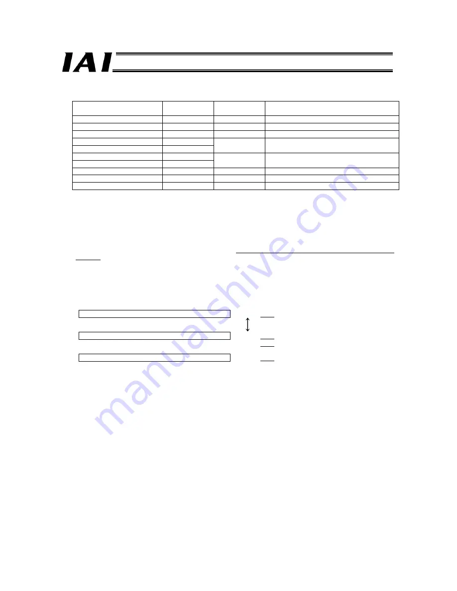
Position Data Load Command (PWRT)
z
Query
Field name
RTU mode data
(8 bits)
Data length
(bytes)
Remarks
Header None
-
Slave address
3F H
1
Fixed.
Function code
06 H
1
Starting address
(upper)
F6 H
Starting address
(lower)
0B H
2
Address of the control signal register of axis (0)
New data (data written) (upper)
06 H
New data (data written) (lower)
10 H
2
The MODE, PWRT and SON signals are “1.”
Error check
(CRC)
16 bits
2
(CD32) Based on calculation result
Trailer None
-
Total bytes
8
z
Response
If the data has been changed (written) successfully, the response is the same as the query.
[Function]
When the PWRT signal changes from “0” to “1” while in the teaching mode (MODE = “1”) and this condition is
maintained for 20 msec or more after it is recognized by the controller, the current position data will be written to the
target position corresponding to the position number in the command position number register effective at the time of
detection.
If the position table is empty, the default parameters will be written together in the data fields other than the target
position (positioning band, speed, acceleration/deceleration).
z
Actual Example (Axis 0)
Load the teaching position into No. 8 of the axis (0) position table.
Inching operation in the teaching mode (MODE = “1”)
3F06F60B0530CC1A
(Repeated inching operations)
Specification of command position number (Ex: 8)
3F06F60B0430CD8A
3F06F60A00089F58
Position data load command
3F06F60B0610CD32
Summary of Contents for RoboNet
Page 1: ...Operation Manual Forth Edition ROBONET ...
Page 257: ...237 Part 2 Startup Chapter X Installed face down X Installed face up ...
Page 354: ...334 ...
Page 395: ...375 ...
Page 396: ...376 ...
Page 397: ...377 ...


