6-51
7. MALFUNCTION OF PUMP 3 PRESSURE SENSOR
7. MALFUNCTION OF PUMP 3 PRESSURE SENSOR
Before carrying out below procedure, check all the related connectors are properly inserted.
INSPECTION PROCEDURE
INSPECTION PROCEDURE
※
1)
1)
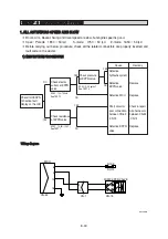
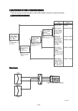
Wiring diagram
Wiring diagram
CN-52
32
MCU
CN-51
3
13
CD-44
PUMP 3 PRESSURE SENSOR
SUPPLY
SIG
RETURN
A
B
C
CN-1
4
6
7
300L6MS09
Cause
Remedy
Defective MCU
Short circuit or
poor connection
between CN-52-
(32)-CN-1(7)
Detective P3
pressure sensor
Short circuit or
poor connection
between CN-1(7)-
CD-44(B)
Short circuit or
poor connection
between
CD-44(A)-CN-1(4)
or CD-44(C)-CN-1
(6)
Short circuit or
poor connection
between CN-1(4)-
CN-51(3) or CN-1
(6) - CN-51(13)
Replace
Replace or repair
Replace or repair
Replace or repair
Replace or repair
Replace or repair
Check voltage
between CN-52
(32) - GND
YES
YES
YES
NO
NO
NO
SPEC :
Starting switch ON :
24
±
2V
SPEC :
Starting switch ON :
24
±
2V
Check voltage
between
CN-1(4)-(6)
Check voltage
between
CN-1(7)-GND
Check voltage
between
CD-44(A)-(C)
YES
NO
SPEC :
Actuator operating: 1~5V
See TEST 11
SPEC :
Actuator operating: 1~5V
Summary of Contents for HX145 LCR
Page 11: ...SECTION 1 GENERAL SECTION 1 GENERAL Group 1 Safety Hints 1 1 Group 2 Specifications 1 10...
Page 204: ...4 5 MEMORANDUM HYUNDAI HEAVY INDUSTRIES CO LTD CONSTRUCTION EQUIPMENT DIV...
Page 627: ...8 155 125LCR8TM30 Turn casing 1 upside down and remove oil seal 3 using jig 29...
Page 657: ...8 185 8 185 Remove lock nut 22 and then boot 23 14 36078RL14 2507ARL10...


