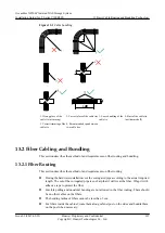
background image


Checking Tools and Materials

Check the following items:

l

Ensure that all necessary tools, such as the diagonal pliers, RJ-45 crimping tool, and blades
(knives), are available.

l

Ensure that the necessary materials, such as the shielded RJ-45 connectors and the category
5e cables, are available. 

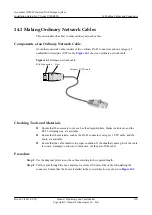
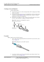
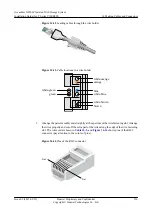
Figure 14-8

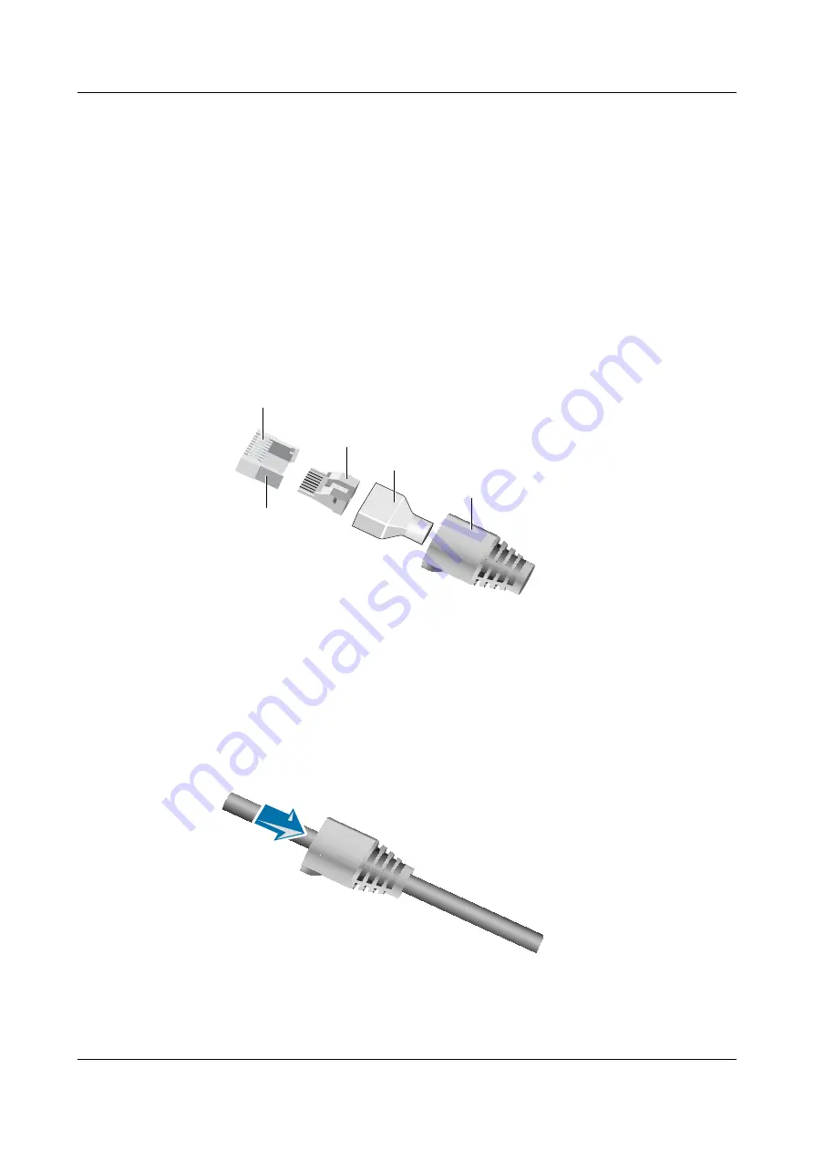
 shows the shielded RJ-45 connector, which has a

shielded iron cover and a wire fastening slot.

l

Ensure that the cable sheath is in proper condition. If the sheath round a part of the cable
is convex, uneven in thickness, or damaged, cut the part off the cable.

Figure 14-8

 Components of a shielded RJ-45 connector

Metal cover on the RJ-45 connector

Plastic cover of the
RJ-45 connector

Wire fastening slot

Shield iron cover

Boot


Procedure

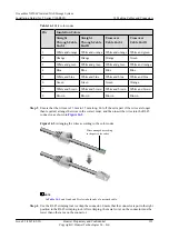
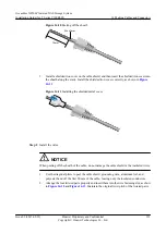
Step 1

Install the boot of the RJ-45 connector.
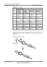
1.

Select a cable of proper length and install the boot on the RJ-45 connector of the cable, as
shown in 

Figure 14-9

.

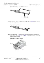
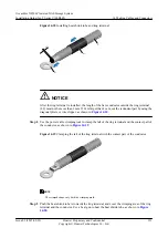
Figure 14-9

 Installing the boot of the RJ-45 connector


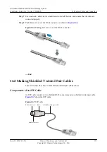
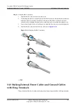
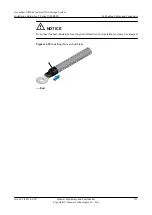
2.

Use a blade or a knife to peel off 30 mm of the sheath and use a blade to slit up to 5 mm
on the sheath, as shown in 

Figure 14-10

.

OceanStor N8500 Clustered NAS Storage System
Installation Guide (for T Series V100R005)

14 Making Cables and Connectors

Issue 02 (2015-09-22)

Huawei Proprietary and Confidential

Copyright © Huawei Technologies Co., Ltd.

314

Summary of Contents for OceanStor N8500 T Series

Page 1: ...OceanStor N8500 Clustered NAS Storage System V200R002 Installation Guide for T Series V100R005 Issue 02 Date 2015 09 22 HUAWEI TECHNOLOGIES CO LTD ...

Page 2: ...cument may not be within the purchase scope or the usage scope Unless otherwise specified in the contract all statements information and recommendations in this document are provided AS IS without warranties guarantees or representations of any kind either express or implied The information in this document is subject to change without notice Every effort has been made in the preparation of this d...

Page 3: ...ber 210235G6GUZ0C3000008 Product Version V100R005C02 admin View this document when the storage unit version is T Series V100R005 Intended Audience This document describes the hardware installation of the clustered NAS Network attached Storage This document covers the following parts precautions and preparations installation flow cabling installation check power on and status indicator check This d...

Page 4: ...used to address practices not related to personal injury NOTE Calls attention to important information best practices and tips NOTE is used to address information not related to personal injury equipment damage and environment deterioration Update History Updates between document issues are cumulative Therefore the latest document issue contains all updates made in previous issues Updates in Issue...

Page 5: ...ustable Guide Rails for an SUC 43 5 6 Installing an SUC 46 5 7 Installing Adjustable Guide Rails for an SUD 47 5 8 Installing an SUD 50 5 9 Installing Adjustable Guide Rails for a Fibre Channel Switch 51 5 10 Installing a Fibre Channel Switch 54 5 11 Installing Adjustable Guide Rails for an Ethernet Switch 55 5 12 Installing an Ethernet Switch 57 5 13 Installing a Filler Panel 58 5 14 Affixing a L...

Page 6: ...an Ethernet Switch 121 6 13 Installing a Filler Panel 122 6 14 Affixing a Label 123 6 15 Setting Up a Heartbeat Network for CNENs 124 6 16 Connecting CNENs to the Service Network 127 6 17 Connecting SUCs to CNENs 131 6 18 Connecting Multiple SUDs to One SUC 134 6 19 Connecting the CNEN to the Maintenance Terminal 138 6 20 Connecting SUCs to the Maintenance Terminal PC 140 6 21 Connecting Ground Ca...

Page 7: ...ode 233 8 3 Applying for a License in Password Activation Mode 235 9 System Initialization 239 10 Solutions for Connecting SUCs to CNENs 249 10 1 Directly Connecting CNENs to SUCs with the S2600T Storage System as the Storage Unit 250 10 2 Directly Connecting CNENs to SUCs with the S5500T Storage System as the Storage Unit 258 10 3 Directly Connecting CNESs to SUCs with the S5600T S5800T or S6800T...

Page 8: ...iber 338 17 2 How to Plug and Unplug a mini SAS Cable 339 17 3 In What Order to Insert The Expansion Network Adapter to The SUC When The S5600T S5800T or S6800T Is Configured 340 17 4 How to Install a Cable Tray 340 17 5 Can be Coffer Disks Exchanged with Other Hard Disks 342 17 6 How to Unload The ISM That Is Installed on The Terminal 342 17 7 In What Sequence Do I Insert a Network Adapter into a...

Page 9: ...lossary 353 OceanStor N8500 Clustered NAS Storage System Installation Guide for T Series V100R005 Contents Issue 02 2015 09 22 Huawei Proprietary and Confidential Copyright Huawei Technologies Co Ltd viii ...

Page 10: ...ining the equipment follow the electrical safety regulations to ensure the safety of the human body and the equipment 1 3 Laser When installing and maintaining the equipment follow the safety regulations of laser to ensure the safety of the human body and the equipment 1 4 Miscellaneous When installing and maintaining the equipment follow the safety regulations of heavy objects sharp objects insta...

Page 11: ...ons Only trained and qualified personnel can install or maintain the device 1 2 Electrical Safety When installing and maintaining the equipment follow the electrical safety regulations to ensure the safety of the human body and the equipment High Voltage DANGER The high voltage power supply offers power for the device operation Direct or indirect contact through damp objects with high voltage and ...

Page 12: ...that the power cable and label conform to the requirements of the actual installation Tools WARNING Use special tools when performing high voltage and AC operations Drilling Holes NOTICE Drilling on the rack without permission is strictly prohibited Drilling that does not satisfy the requirements concerned may damage the wires and cables inside the rack If the metal shavings from the drilling get ...

Page 13: ...uman body generates static electricity due to body movements friction between the shoes and floor friction between clothes and contact with plastic objects Electrostatic Discharge ESD remains on the human body for a long time l Before touching the device or holding the boards circuit boards or ASICs wear an ESD wrist strap and make sure that it is properly grounded This can prevent the sensitive c...

Page 14: ...nnector l Use an attenuator to prevent high optical power from damaging the optical receiver while using a fiber jumper for the hardware loopback on an optical interface l Before using an optical time domain reflectometer OTDR remove the fiber jumper between the opposite site and the optical interface module Such a measure also prevents high optical power from damaging the optical receiver l Do no...

Page 15: ...ot allow circuits of one module to touch those of another module as this can cause short circuit or can damage the module l When holding a module do not touch the module circuits components connectors or connection slots Bundling Signal Cables NOTICE Bundle the signal cables separately from the strong current cables or high voltage cables The space between two adjacent ties must be at least 30 mm ...

Page 16: ... models l Ethernet switch An Ethernet switch is required for a heartbeat network only when more than two CNENs are installed It is advisable to install two Ethernet switches for redundancy l Fibre Channel switch A Fibre Channel switch is required to provide additional ports when ports are insufficient in a direct connection between the CNEN and SUC It is advisable to install two Fibre Channel swit...

Page 17: ...r CNENs two SUCs housing 3 5 inch hard disks twelve SUDs two Fibre Channel switches and two Ethernet switches Figure 2 1 Hardware structure with the S2600T or S5500T storage system as the storage unit N8500 Hardware Structure with the S5600T S5800T or S6800T Storage System as the Storage Unit Figure 2 2 shows the N8500 hardware structure with the S5600T S5800T or S6800T storage system as the stora...

Page 18: ...rage system as the storage unit 2 1 Before You Install Making plans for power distribution device assembling system maintenance IP address assignment and device cascading can facilitate device installation 2 2 Installation Procedure Learning about the overall installation procedure prior to installing the N8500 will greatly facilitate the subsequent operations OceanStor N8500 Clustered NAS Storage...

Page 19: ...ircuits of the device whose power input works in N 1 backup mode connect to different branches of the power supply 2 Devices in the cabinet are effectively protected against overvoltage and short circuits 3 Devices except the devices that require device level backup and the accessories that do not affect services in the cabinet are provided with non disruptive power supply 4 A PDU is configured in...

Page 20: ...re cabinet and meet heat dissipation requirements in the equipment room depending on the actual heat dissipation condition l At least a clearance of 120 cm is available between cabinets and 100 cm between a cabinet and the wall l A pair of delivery attached guide rails can bear a component of more than 50 kg l Components are arranged in convenient locations for cabling Space is reserved for future...

Page 21: ...sembling may vary depending on the number of components cabinet models and disk specifications Figure 2 4 shows an N8500 that is equipped with two clustered NAS engine enclosures one SUC 4 U two Fibre Channel switches and two Ethernet switches OceanStor N8500 Clustered NAS Storage System Installation Guide for T Series V100R005 2 Getting Started Issue 02 2015 09 22 Huawei Proprietary and Confident...

Page 22: ...or one serial port are ready l The available disk space must remain more than 500 MB l Table 2 2 lists the operating systems and browser versions required for the PC that runs the Integrated Storage Manager ISM Table 2 2 Operating environment requirements for the PC that running the ISM Operating System Browser Windows Server 2003 Enterprise Edition SP2 l Internet Explorer 7 0 OceanStor N8500 Clus...

Page 23: ...ter Windows Server 2003 Standard Edition SP2 Windows XP Professional SP2 Windows 7 You are advised to install Java Runtime Environment JRE 1 6 0_20 for matching the ISM If a version earlier than JRE 1 6 0_20 has been installed on the client JRE 1 6 0_20 will replace the earlier one and take effect immediately after being installed If a version later than JRE 1 6 0_20 has been installed uninstall t...

Page 24: ...engine is provided for services You are advised to set it on the same network segment as the physical IP address of the engine otherwise configure switches for the same purpose The physical and virtual IP address segments reserved for the clustered NAS engine must be consecutive and do not overlap You are advised to reserve IP addresses that are two times the number of network ports that will be a...

Page 25: ...ervice IP address and console IP address management IP address shown in Table 2 4 Table 2 4 IPv4 address configuration table Type IP Address Subnet Mask Gateway Physical IP address segment of the clustered NAS enginea ___ ___ ___ ___b to ___ ___ ___ ___ ___ ___ ___ ___ ___ ___ __ _ ___ Virtual IP address segment of the clustered NAS engine ___ ___ ___ ___c to ___ ___ ___ ___ ___ ___ ___ ___ Consol...

Page 26: ...t only and initialize the password of user master root and support respectively to Master stor age Root storag e and support sto rage run the initpasswd command to initialize the password _super_admin Admin revive Use the serial port to log in as user _super_admin Run chgpasswd to reset the password and confirm it NOTE Change your password for security purposes Keep the password properly and if th...

Page 27: ...ne node as master Run admin passwd or admin passwd master to change the password NOTE l Change your password for security purposes l Any change made for the password of user master will be synchronized to the passwords of user admin of the storage unit and user admin of the baseboard management controller BMC on the clustered NAS engine enclosure After the synchronizati on the passwords of user ma...

Page 28: ...the operating status and service configurations of the N8000 but cannot configure and upgrade the N8000 or add and delete users l Log in to the engine node as master Run admin passwd xxx to change the password ere xxx indicates a known read only administrator l Log in to the engine node as the read only administrator Run admin passwd xxx to change the password ere xxx indicates the read only admin...

Page 29: ... Change your password for security purposes SUC Super administrator This user can take full control over storage units and create a low level of users admin Admin storage Any change made for the password of user master will be synchronized to the password of user admin After the synchronization the passwords of user master and user admin are the same NOTE Change your password for security purposes...

Page 30: ...ity purposes Hardwar e manage ment This user can monitor the N8000 engine status admin Master storage Any change made for the password of user master will be synchronized to the passwords of user admin of the storage unit and user admin of the baseboard management controller BMC on the clustered NAS engine enclosure After the synchronization the passwords of user master and user admin are the same...

Page 31: ...n a non domain environment this level of users can access CIFS services Log in to the engine node as user master In CIFS sharing management mode run the local password username command to change the password NOTE Change your password for security purposes File Transfer Protocol FTP services Read Only user created by the ISM or CLI This level of users can read data in a specified FTP directory usin...

Page 32: ...d NOTE Change your password for security purposes NDMP service access R W user This level of users can be used for the authentication between the NDMP host and backup software ndmp ndmp st orage Log in to the engine node as user master In NDMP management mode run the chgpwd username command to change the password NOTE Change your password for security purposes OceanStor N8500 Clustered NAS Storage...

Page 33: ... engine or super administrator user of SUC to log in to the device for maintenance maintenance commands apply only to scenarios in which faults cannot be located by using common maintenance methods Incorrect use of the maintenance commands may cause exceptions on devices or service interruptions If you need to use the maintenance commands apply for the permission to Huawei Technologies Co Ltd l If...

Page 34: ...server is an external mail server and is normally prepared by users themselves Therefore if users need to change the login password of the SMTP server they can contact the system administrators Port Status Configuration Plan When configuring and using the N8500 ports enable or disable corresponding ports 2 2 Installation Procedure Learning about the overall installation procedure prior to installi...

Page 35: ...lation requirements 2 Install guide rails and front panels according to the assembling plan and cable all components according to the networking plan 3 Power on the N8500 in a correct power on sequence Determine whether the N8500 is successfully powered on according to indicator status 4 Initialize the N8500 by referring to the associated chapter 5 Use the ISM to configure desired functions OceanS...

Page 36: ...d has a cross head Diagonal pliers Used to cut insulation pipes and cable ties Crimper Used to crimp the ends of metallic pipes when making coaxial cables Paper knife Used to cut tapes on the carton Floating nut mounting bar Used to assemble and disasseble floating nuts ESD clothes Used to prevent electrostatic discharges OceanStor N8500 Clustered NAS Storage System Installation Guide for T Series...

Page 37: ...s Name Legend Function Multimeter Used to test cabinet insulation cable connectivity and device electrical performance including the voltage current and resistance Network cable tester Used to test network cable connectivity OceanStor N8500 Clustered NAS Storage System Installation Guide for T Series V100R005 3 Tools Preparation Issue 02 2015 09 22 Huawei Proprietary and Confidential Copyright Hua...

Page 38: ...he size of the equipment room must be enough for product installation and capacity expansion The floor can meet the requirements for the bearing weight The cabling slot ladder and hole are complete or ready The decoration is complete 3 Air conditioner If the temperature in the room exceeds 35 C install air conditioners which can be restarted after power off Do not let the air conditioner blow dire...

Page 39: ...round lead in should not be longer than 30 m and should use the zinc coated flat steel whose cross sectional area is equal to or more than 40 mm x 4 mm The contact point should be handled for insulation and anticorrosive purposes The above ground steel should be provided with measures to avoid mechanical damage and should be intact without soldering points for the break 10 Lightning protection The...

Page 40: ...osive airborne contaminants in the equipment room a ISO International Organization for Standardization b Å is a unit of length equal to 1 10000000000 one ten billionth of a meter c ANSI American National Standards Institute d ISA Instrument Society of America OceanStor N8500 Clustered NAS Storage System Installation Guide for T Series V100R005 4 Checking the Installation Environment Issue 02 2015 ...

Page 41: ...placed into different depths of cabinets 5 4 Installing a Clustered NAS Engine Enclosure Installing a clustered NAS engine enclosure into a cabinet includes sliding the clustered NAS engine enclosure into the cabinet securing the clustered NAS engine enclosure and checking the installation result 5 5 Installing Adjustable Guide Rails for an SUC Before assembling an SUC you must install adjustable ...

Page 42: ... for a signal cable and for a power cable 5 15 Setting Up a Heartbeat Network for CNENs This section explains how to set up a heartbeat network for CNENs The heartbeat network provides a platform for CNENs 2 or 4 to perceive and communicate with 5 16 Connecting CNENs to the Service Network This section explains how to connect CNENs to the NAS service network 5 17 Connecting SUCs to CNENs This sect...

Page 43: ... indicators on the N8500 to determine whether the entire system is properly operating 5 25 Installing a Front Panels After all components are installed and properly powered up install front panels for a neat appearance OceanStor N8500 Clustered NAS Storage System Installation Guide for T Series V100R005 5 N8500 Installation with the S2600T Storage System as the Storage Unit Issue 02 2015 09 22 Hua...

Page 44: ...he local office and maintains the defective goods including internal and external packages for later investigations l If goods are in good condition the project superior and customer representative sign the Packing List NOTE The Packing List is an information list attached to the packing box It provides information about the purchase orders customer names and other delivery materials When you have...

Page 45: ...NAS engine enclosure l Adjustable guide rails l Front panels l Network cables l Optical fibers l AC power cables l Ground cables OceanStor N8500 Clustered NAS Storage System Product Documentation OceanStor N8500 Clustered NAS Storage System Installation Guide for T Series V100R005 5 N8500 Installation with the S2600T Storage System as the Storage Unit Issue 02 2015 09 22 Huawei Proprietary and Con...

Page 46: ...hannel Switch Product Documentation Ethernet switches l Ethernet switch enclosures l Adjustable guide rails l Ground cables l AC power cables S5300 Product Document 5 2 Removing a Filler Panel from a Cabinet If the planned installation locations in a cabinet are covered with filler panels remove them before installing devices If the planned installation locations are not covered by filler panels s...

Page 47: ...e cabinet Step 3 Use a floating nut mounting bar to remove floating nuts NOTE If no floating nut mounting bar is available use a flat head screwdriver instead When you use a flat head screwdriver to remove floating nuts exercise special care to prevent it from injuring your hands or damaging devices End OceanStor N8500 Clustered NAS Storage System Installation Guide for T Series V100R005 5 N8500 I...

Page 48: ...ls l Each clustered NAS engine enclosure is equipped with a pair of adjustable guide rails l Guide rails can be flexibly adjusted from 600 mm to 900 mm and installed in the cabinet with a depth from 800 mm to 1200 mm l Adjustable guide rails come preinstalled with square hole positioning pins If required change square hole positioning pins to round hole ones before installing adjustable guide rail...

Page 49: ...adjustable guide rail with the desired U position on the front and rear channels 2 Extend the adjustable guide rail until the front and rear positioning pins protrude through the holes on the front and rear channels 3 Use M6 screws to secure the adjustable guide rail OceanStor N8500 Clustered NAS Storage System Installation Guide for T Series V100R005 5 N8500 Installation with the S2600T Storage S...

Page 50: ...abinet includes sliding the clustered NAS engine enclosure into the cabinet securing the clustered NAS engine enclosure and checking the installation result Prerequisites Adjustable guide rails have been assembled The following tools and materials have been ready l M6 screws l Phillips screwdriver M3 to M6 l Floating nuts OceanStor N8500 Clustered NAS Storage System Installation Guide for T Series...

Page 51: ...ling a floating nut Step 2 Place the floating nut mounting bar on the top of the floating nut and pull it into the hole until it snaps into place as shown in step 2 of Figure 5 3 Step 3 Check the floating nut to ensure that it has been properly seated as shown in step 3 of Figure 5 3 Step 4 Slide the clustered NAS engine enclosure into the cabinet as shown in step 1 of Figure 5 4 Step 5 Use M6 scr...

Page 52: ...adjustable guide rails to bear it With the adjustable guide rails an SUC can be placed into different depths of cabinets Prerequisites The following tools and materials have been ready l Phillips screwdriver M3 to M6 l Marker pen l M6 screws l Square hole positioning pins matching square hole channels l Round hole positioning pins matching round hole channels OceanStor N8500 Clustered NAS Storage ...

Page 53: ...e guide rails Figure 5 5 shows the screw hole locations Figure 5 5 Screw hole locations Procedure Step 1 Install the left adjustable guide rail with an L identifier NOTE If there is no scale marked on the channels mark the scale from the bottom 1 U position upwards Be sure to horizontally line up the front and rear of the adjustable guide rail 1 Align the underside of the adjustable guide rail wit...

Page 54: ...e guide rail with an R identifier OceanStor N8500 Clustered NAS Storage System Installation Guide for T Series V100R005 5 N8500 Installation with the S2600T Storage System as the Storage Unit Issue 02 2015 09 22 Huawei Proprietary and Confidential Copyright Huawei Technologies Co Ltd 45 ...

Page 55: ...ews l Phillips screwdriver M3 to M6 Context CAUTION The SUC is heavy and should be installed into a cabinet by two people Procedure Step 1 Slide the SUC into the cabinet as shown in step 1 of Figure 5 6 Step 2 Use M6 screws to secure the SUC into the cabinet as shown in step 2 of Figure 5 6 OceanStor N8500 Clustered NAS Storage System Installation Guide for T Series V100R005 5 N8500 Installation w...

Page 56: ...rent depths of cabinets Prerequisites The following tools and materials have been ready l Phillips screwdriver M3 to M6 l Marker pen l M6 screws l Square hole positioning pins matching square hole channels l Round hole positioning pins matching round hole channels OceanStor N8500 Clustered NAS Storage System Installation Guide for T Series V100R005 5 N8500 Installation with the S2600T Storage Syst...

Page 57: ...e guide rails Figure 5 7 shows the screw hole locations Figure 5 7 Screw hole locations Procedure Step 1 Install the left adjustable guide rail with an L identifier NOTE If there is no scale marked on the channels mark the scale from the bottom 1 U position upwards Be sure to horizontally line up the front and rear of the adjustable guide rail 1 Align the underside of the adjustable guide rail wit...

Page 58: ...r details on how to install the right adjustable guide rail see Step 1 OceanStor N8500 Clustered NAS Storage System Installation Guide for T Series V100R005 5 N8500 Installation with the S2600T Storage System as the Storage Unit Issue 02 2015 09 22 Huawei Proprietary and Confidential Copyright Huawei Technologies Co Ltd 49 ...

Page 59: ...UD is heavy and should be installed into a cabinet by three people Before installing a 4 U SUD install floating nuts nowhere but at the marked positions above the adjustable guide rails since adjustable guide rails themselves provide screw holes for securing the SUD Procedure Step 1 Insert the lower end of a floating nut into a planned square hole as shown in step 1 of Figure 5 8 Figure 5 8 Instal...

Page 60: ...properly installed and secured Step 7 If multiple SUDs are required repeat Step 1 to Step 6 for other SUDs End 5 9 Installing Adjustable Guide Rails for a Fibre Channel Switch Before assembling a Fibre Channel switch you must install adjustable guide rails to bear it With the adjustable guide rails a Fibre Channel switch can be placed into different depths of cabinets Prerequisites The following t...

Page 61: ...n securing screws l Four screws are used to secure the adjustable guide rails Figure 5 10 shows the screw hole locations Figure 5 10 Screw hole locations Procedure Step 1 Install the left adjustable guide rail with an L identifier NOTE If there is no scale marked on the channels mark the scale from the bottom 1 U position upwards Be sure to horizontally line up the front and rear of the adjustable...

Page 62: ...see Step 1 Step 3 If multiple Fibre Channel switches are required repeat Step 1 to Step 2 for other Fibre Channel switches End OceanStor N8500 Clustered NAS Storage System Installation Guide for T Series V100R005 5 N8500 Installation with the S2600T Storage System as the Storage Unit Issue 02 2015 09 22 Huawei Proprietary and Confidential Copyright Huawei Technologies Co Ltd 53 ...

Page 63: ...igure 5 11 Figure 5 11 Installing mounting brackets for the Fibre Channel switch Step 2 Secure the Fibre Channel switch into the cabinet as shown in step 1 of Figure 5 12 Step 3 Install and extend the adjustable guide rails of the Fibre Channel switch as instructed by step 2 in Figure 5 12 Step 4 Use eight screws to secure the Fibre Channel switch to the cabinet as shown in step 3 of Figure 5 12 O...

Page 64: ...ble guide rails an Ethernet Switch can be placed into different depths of cabinets Prerequisites The following tools and materials have been ready l Phillips screwdriver M3 to M6 l Marker pen l M6 screws l Round hole positioning pins matching round hole channels Context NOTICE Stacking storage devices will damage devices therefore storage devices must be placed on adjustable guide rails OceanStor ...

Page 65: ...r NOTE If there is no scale marked on the channels mark the scale from the bottom 1 U position upwards Be sure to horizontally line up the front and rear of the adjustable guide rail 1 Align the underside of the adjustable guide rail with the desired U position on the front and rear channels 2 Extend the adjustable guide rail until the front and rear positioning pins protrude through the holes on ...

Page 66: ... is installed into the cabinet you are advised to connect ground cables before installing the Ethernet switch Procedure Step 1 Installing mounting ears for the Ethernet switch Step 2 Slide the Ethernet switch along the adjustable guide rails into the cabinet as shown in step 1 of Figure 5 14 Step 3 Use two screws to secure the Ethernet switch to the cabinet as shown in step 2 of Figure 5 14 OceanS...

Page 67: ... with filler panels to ensure proper ventilation and neat appearance of the cabinet Prerequisites The following tools and materials have been ready l Filler panels l M6 screws l Phillips screwdriver M3 to M6 Procedure Step 1 Use M6 screws to secure the filler panel to the cabinet OceanStor N8500 Clustered NAS Storage System Installation Guide for T Series V100R005 5 N8500 Installation with the S26...

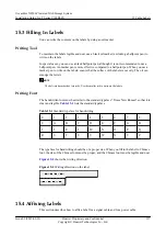
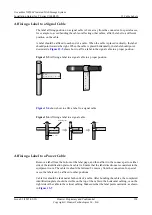
Page 68: ...able A label should be affixed to each end of a cable When the cable is placed vertically the label should point rightwards When the cable is placed horizontally the label should point downwards Figure 5 15 shows how to attach a label to the signal cable in a proper position Figure 5 15 Affixing a label to a signal cable in a proper position 1 06 A 01 2 A TO 1 06 A 01 2 A TO Figure 5 16 shows how ...

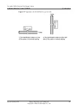
Page 69: ...n plate should be visible on the top of the cable in the horizontal cabling or on the right side of the cable in the vertical cabling Make sure that the label points outwards as shown in Figure 5 17 Figure 5 17 Appearance of a label affixed to a power cable 5 15 Setting Up a Heartbeat Network for CNENs This section explains how to set up a heartbeat network for CNENs The heartbeat network provides...

Page 70: ...rk ports Figure 5 18 Directly connecting heartbeat network ports on two CNENs If one N8500 is equipped with four CNENs you must configure two Ethernet switches network all CNENs as shown in Figure 5 19 OceanStor N8500 Clustered NAS Storage System Installation Guide for T Series V100R005 5 N8500 Installation with the S2600T Storage System as the Storage Unit Issue 02 2015 09 22 Huawei Proprietary a...

Page 71: ...OTICE During the system operation ensure that heartbeat network port P0 is connected Otherwise system management may be abnormal l Direct connection 1 Connect one end of the network cable to heartbeat network port P0 on one CNEN and the other end to heartbeat network port P0 on the other CNEN OceanStor N8500 Clustered NAS Storage System Installation Guide for T Series V100R005 5 N8500 Installation...

Page 72: ...AS service network Prerequisites The following tools and materials have been ready l Network cables and cable ties l Optical fibers fiber bundling tapes 8 Gbit s optical transceivers applied when the CNEN is equipped with a 10 Gbit s network adapter l Diagonal pliers Context By default each CNEN is equipped with four service network ports CNENs can connect to the service host directly or through s...

Page 73: ...rk ports by adding one to three 1 Gbit s network adapters Figure 5 21 shows the slots and network for a CNEN to add one 1 Gbit s network adapter OceanStor N8500 Clustered NAS Storage System Installation Guide for T Series V100R005 5 N8500 Installation with the S2600T Storage System as the Storage Unit Issue 02 2015 09 22 Huawei Proprietary and Confidential Copyright Huawei Technologies Co Ltd 64 ...

Page 74: ...ice network ports by adding one to three 10 Gbit s network adapters Figure 5 22 shows the slots and network for a CNEN to add one 10 Gbit s network adapter OceanStor N8500 Clustered NAS Storage System Installation Guide for T Series V100R005 5 N8500 Installation with the S2600T Storage System as the Storage Unit Issue 02 2015 09 22 Huawei Proprietary and Confidential Copyright Huawei Technologies ...

Page 75: ...bit s service network optical ports by adding one or two 1 Gbit s optical port adapters Figure 5 23 shows the slots and network for a CNEN to add one 1 Gbit s optical port adapter OceanStor N8500 Clustered NAS Storage System Installation Guide for T Series V100R005 5 N8500 Installation with the S2600T Storage System as the Storage Unit Issue 02 2015 09 22 Huawei Proprietary and Confidential Copyri...

Page 76: ...st directly l The service host through the Ethernet or Fibre Channel switch Step 3 Repeat Step 1 to Step 2 to connect other CNENs to the service network Step 4 Route and bundle cables NOTE For details on how to route and bundle mini cables see 12 General Cable Routing Description and 13 Basic Cable Routing and Bundling Technology End 5 17 Connecting SUCs to CNENs This section explains how to conne...

Page 77: ...r HBA to the CNEN for providing more Fibre Channel ports to connect directly to SUCs For details on how to add Fibre Channel ports and obtain information about direct connection see 10 1 Directly Connecting CNENs to SUCs with the S2600T Storage System as the Storage Unit As shown in Figure 5 25 a switch connection network contains the following parts l 2 to 4 CNENs l 1 to 18 SUCs l Support for onl...

Page 78: ...Set up a network containing the cluster NAS engine and storage control unit l Direct connection Connect 4 or 8 Fibre Channel ports on each CNEN respectively to two 8 Gbit s Fibre Channel port on SUC s controllers A and B l Switch connection OceanStor N8500 Clustered NAS Storage System Installation Guide for T Series V100R005 5 N8500 Installation with the S2600T Storage System as the Storage Unit I...

Page 79: ...xpansion loop one consisting of ports EXP 0 on SUC s controllers A and B and the other consisting of ports EXP 1 on SUC s controllers A and B The number of SUDs in each expansion loop should be consistent l In the expansion loops that contains more than one SUDs the SUC s controllers A and B connect to SUDs in opposite directions The positive direction goes from the SUC s controller A port PRI on ...

Page 80: ... SUC s controllers A and B to ports PRI on one SUD s disk modules A and B One expansion loop is generated Then attach ports EXP 1 on the SUC s controllers A and B to ports PRI on the other SUD s disk modules A and B The other expansion loop is generated as shown in Figure 5 27 OceanStor N8500 Clustered NAS Storage System Installation Guide for T Series V100R005 5 N8500 Installation with the S2600T...

Page 81: ...nd two SUDs to the other expansion loop as shown in Figure 5 28 OceanStor N8500 Clustered NAS Storage System Installation Guide for T Series V100R005 5 N8500 Installation with the S2600T Storage System as the Storage Unit Issue 02 2015 09 22 Huawei Proprietary and Confidential Copyright Huawei Technologies Co Ltd 72 ...

Page 82: ...Connecting SUDs to One SUC with the S2600T as the Storage Unit OceanStor N8500 Clustered NAS Storage System Installation Guide for T Series V100R005 5 N8500 Installation with the S2600T Storage System as the Storage Unit Issue 02 2015 09 22 Huawei Proprietary and Confidential Copyright Huawei Technologies Co Ltd 73 ...

Page 83: ...al After the CNEN is connected to the maintenance terminal you can utilize the maintenance terminal to manage and maintain the CNEN Prerequisites The following tools and materials have been ready l Network cables collaborating with management network ports l RJ 45 to DB9 serial cables or double RJ 45 serial cables collaborating with serial ports l Cable ties l Diagonal pliers Context CNENs can be ...

Page 84: ...ne serial port for connecting to the PC Figure 5 30 Connecting the serial port to a maintenance terminal OceanStor N8500 Clustered NAS Storage System Installation Guide for T Series V100R005 5 N8500 Installation with the S2600T Storage System as the Storage Unit Issue 02 2015 09 22 Huawei Proprietary and Confidential Copyright Huawei Technologies Co Ltd 75 ...

Page 85: ... the maintenance terminal l Connecting the serial port to the maintenance terminal 1 Insert one end of the RJ 45 serial cable to a specified CNEN serial port 2 Connect the other end DB9 or RJ45 connector of the serial port to a serial port on the maintenance terminal Step 3 Route and bundle cables NOTE For details on how to route and bundle cables see 12 General Cable Routing Description and 13 Ba...

Page 86: ...SUC to the PC through a serial port Procedure Step 1 Determine a connection mode The methods of connecting SUCs to the PC and managing the SUCs and SUDs are provided as follows l Procedure for connecting SUCs to the PC through management network ports is Manage SUCs and SUDs on the ISM l Procedure for connecting SUCs to the PC through a serial port is OceanStor N8500 Clustered NAS Storage System I...

Page 87: ...and bundle serial cables or management network cables see 12 General Cable Routing Description and 13 Basic Cable Routing and Bundling Technology End 5 21 Connecting Ground Cables The N8500 must be grounded to prevent damage caused by static electricity or dangers caused by unexpected creepage Prerequisites The cabinet has been connected to the group pole in the equipment room Procedure Step 1 Con...

Page 88: ... SUD ground point 2 Protrude the screw through the OT of the ground cable and secure the screw to the SUD ground point OceanStor N8500 Clustered NAS Storage System Installation Guide for T Series V100R005 5 N8500 Installation with the S2600T Storage System as the Storage Unit Issue 02 2015 09 22 Huawei Proprietary and Confidential Copyright Huawei Technologies Co Ltd 79 ...

Page 89: ...he cabinet OceanStor N8500 Clustered NAS Storage System Installation Guide for T Series V100R005 5 N8500 Installation with the S2600T Storage System as the Storage Unit Issue 02 2015 09 22 Huawei Proprietary and Confidential Copyright Huawei Technologies Co Ltd 80 ...

Page 90: ... ground cable and secure the screw to the clustered NAS engine enclosure ground point 3 Use a screw to secure the other end of the ground cable to the cabinet OceanStor N8500 Clustered NAS Storage System Installation Guide for T Series V100R005 5 N8500 Installation with the S2600T Storage System as the Storage Unit Issue 02 2015 09 22 Huawei Proprietary and Confidential Copyright Huawei Technologi...

Page 91: ... has been disconnected from all external power sources The following peak power required by each component can be achieved l Clustered NAS engine enclosure 830 W l SUC 380 W l SUD 480 W l Fibre Channel switch 90 W l Ethernet switch 63 W OceanStor N8500 Clustered NAS Storage System Installation Guide for T Series V100R005 5 N8500 Installation with the S2600T Storage System as the Storage Unit Issue...

Page 92: ...wer cable that comes with each component to the power socket of the rear panel Step 2 Use a buckle to sure the AC power cable 1 While releasing the latch on the buckle as shown in a of step 1 in Figure 5 33 slide the buckle to the joint between the AC power cable and socket as shown in b of step 1 in Figure 5 33 OceanStor N8500 Clustered NAS Storage System Installation Guide for T Series V100R005 ...

Page 93: ...s see 12 General Cable Routing Description and 13 Basic Cable Routing and Bundling Technology End 5 23 Powering On the N8500 This section explains how to power on the N8500 after it is installed and cabled Prerequisites l All components have been correctly installed and cabled l The switch of the PDU or PDB has been turned off l The power voltage conforms to device requirements Context Before powe...

Page 94: ... off storage unit disk enclosures disconnecting from the power supply powering off Fibre Channel switches disconnecting from the power supply powering off Ethernet switches turning off the power switches disconnecting from external power supplies DANGER Do not wear the ESD wrist strap during power on to avoid electric shocks Procedure Step 1 Set all switches on the PDU or PDB to On NOTE For detail...

Page 95: ...y referring to 5 24 Checking Indicators and determine whether the N8500 is running correctly If any indicator is red on contact Huawei technical support engineers 5 24 Checking Indicators After the N8500 is powered on view indicators on the N8500 to determine whether the entire system is properly operating Checking Indicators on a clustered NAS engine enclosure Figure 5 34 shows indicators on the ...

Page 96: ...l Off No external power is input 2 Operating or alarm indicator of the fan l Green on indicates that the fan runs normally l Red on The fan is faulty l Off The fan is not powered on 3 Power indicator of the expansion module l Green on The expansion module is properly powered on l Off The expansion module cannot be powered on 4 Active indicator of the network port l Green and blinking Data transfer...

Page 97: ...he controller is faulty l Off indicates that the controller runs normally 9 Power indicator of the enclosure l Green and on The controller enclosure is powered on l Green and blinking The controller enclosure is being powered on or powered off l Off The controller enclosure is not powered on 10 Alarm indicator of the clustered NAS engine enclosure l Red and on The enclosure is out of service or an...

Page 98: ...ink indicator of the expansion port Figure 5 36 Status of indicators on the SUC front view 1 Power indicator of the enclosure 2 Disk running indicator Checking Indicators on an SUD Status of the indicators on a 4 U SUD should look like that shown in Figure 5 37 and Figure 5 38 OceanStor N8500 Clustered NAS Storage System Installation Guide for T Series V100R005 5 N8500 Installation with the S2600T...

Page 99: ...indicators on the SUD front view 1 Power indicator of the enclosure 2 Disk running indicator Checking Indicators on an Ethernet Switch Figure 5 39 shows the indicators on the front panel of an Ethernet switch Figure 5 39 Indicators on the Ethernet switch OceanStor N8500 Clustered NAS Storage System Installation Guide for T Series V100R005 5 N8500 Installation with the S2600T Storage System as the ...

Page 100: ...arm fan alarm or temperature alarm is generated l Off The system is not operating 4 Mode indicator l Green on The service interface indicator indicates the interface speed After 45 seconds the service interface indicator automatically restores to off l Red on The service interface indicator indicates the stack ID After 45 seconds the service interface indicator automatically restores to off l Off ...

Page 101: ...ed to external device but has no traffic l Amber and blinking 2 seconds Port is disabled because of diagnostics or the portdisable command l Amber and blinking 0 5 second Port is faulty l Amber and on for more than 5 seconds Port is receiving light or signal carrier at 4 Gbit s but is not yet online l Off No light or signal carrier on media interface 3 Ethernet Speed indicator l Green and on Port ...

Page 102: ... Use the front panel to cover the front side of SUC or SUC as shown in step 2 of Figure 5 41 Then release the tabs 4 Check the front panel to ensure that it has been proper installed and secured Step 2 Install a front panel for the SUC or SUD 1 Align the upper side of the front panel with that of the SUC or SUD 2 Keep pushing the two tabs towards the center of the front panel as shown in step 1 of...

Page 103: ...gure 5 42 or Figure 5 43 Then release the tabs 4 Check the front panel to ensure that it has been proper installed and secured End OceanStor N8500 Clustered NAS Storage System Installation Guide for T Series V100R005 5 N8500 Installation with the S2600T Storage System as the Storage Unit Issue 02 2015 09 22 Huawei Proprietary and Confidential Copyright Huawei Technologies Co Ltd 94 ...

Page 104: ...laced into different depths of cabinets 6 4 Installing a Clustered NAS Engine Enclosure Installing a clustered NAS engine enclosure into a cabinet includes sliding the clustered NAS engine enclosure into the cabinet securing the clustered NAS engine enclosure and checking the installation result 6 5 Installing Adjustable Guide Rails for an SUC Before assembling an SUC you must install adjustable g...

Page 105: ...bel for a signal cable and for a power cable 6 15 Setting Up a Heartbeat Network for CNENs This section explains how to set up a heartbeat network for CNENs The heartbeat network provides a platform for CNENs 2 or 4 to perceive and communicate with 6 16 Connecting CNENs to the Service Network This section explains how to connect CNENs to the NAS service network 6 17 Connecting SUCs to CNENs This s...

Page 106: ...ors on the N8500 to determine whether the entire system is properly operating 6 25 Installing Front Panels After all components are installed and operating properly after being powered up install front panels for a neat appearance OceanStor N8500 Clustered NAS Storage System Installation Guide for T Series V100R005 6 N8500 Installation with S5500T Storage System as the Storage Unit Issue 02 2015 0...

Page 107: ... the local office and maintains the defective goods including internal and external packages for later investigations l If goods are in good condition the project superior and customer representative sign the Packing List NOTE The Packing List is an information list attached to the packing box It provides information about the purchase orders customer names and other delivery materials When you ha...

Page 108: ...led you can optionally configure a 24 slot SUC housing 2 5 inch hard disks and a 2 U SUD Table 6 1 represents components that shipped with the N8500 OceanStor N8500 Clustered NAS Storage System Installation Guide for T Series V100R005 6 N8500 Installation with S5500T Storage System as the Storage Unit Issue 02 2015 09 22 Huawei Proprietary and Confidential Copyright Huawei Technologies Co Ltd 99 ...

Page 109: ...les l Ground cables l Cable trays l Installation templates SUD l Storage unit disk enclosures l Adjustable guide rails l Front panels l Mini SAS cables l Ground cables l AC power cables l Installation templates Fibre Channel switches l Fibre Channel switch enclosures l Adjustable guide rails l Optical fibers optional l AC power cables SNS2124 Fibre Channel Switch Product Documentation OceanStor N8...

Page 110: ...l Phillips screwdriver M3 to M6 l Optional Flat head screwdriver M3 to M6 l Floating nut mounting bar Procedure Step 1 Use a Phillips screwdriver to remove M6 screws from a filler panel NOTE It is recommended that you reserve 1 U space between every two components to install a filler panel for proper heat dissipation Step 2 Remove the filler panel from the cabinet Step 3 Use a floating nut mountin...

Page 111: ...abinets Prerequisites The following tools and materials have been ready l Phillips screwdriver M3 to M6 l Marker pen l M6 screws l Square hole positioning pins matching square hole channels l Round hole positioning pins matching round hole channels Context NOTICE Stacking storage devices will damage devices therefore storage devices must be placed on adjustable guide rails l Each clustered NAS eng...

Page 112: ...dure Step 1 Install the left adjustable guide rail with an L identifier NOTE If there is no scale marked on the channels mark the scale from the bottom 1 U position upwards Be sure to horizontally line up the front and rear of the adjustable guide rail 1 Align the underside of the adjustable guide rail with the desired U position on the front and rear channels 2 Extend the adjustable guide rail un...

Page 113: ...or details on how to install the right adjustable guide rail see Step 1 OceanStor N8500 Clustered NAS Storage System Installation Guide for T Series V100R005 6 N8500 Installation with S5500T Storage System as the Storage Unit Issue 02 2015 09 22 Huawei Proprietary and Confidential Copyright Huawei Technologies Co Ltd 104 ...

Page 114: ...flat head screwdriver Context CAUTION The clustered NAS engine enclosure is heavy and should be installed into a cabinet by three people Before installing a clustered NAS engine enclosure install floating nuts nowhere but at the marked positions above the adjustable guide rails since adjustable guide rails themselves provide screw holes for securing the clustered NAS engine enclosure Procedure Ste...

Page 115: ...red NAS engine enclosure is horizontally installed and tightly screwed Step 7 If you have more than one clustered NAS engine enclosure Repeat Step 1 to Step 6 install other clustered NAS engine enclosure to the cabinet End 6 5 Installing Adjustable Guide Rails for an SUC Before assembling an SUC you must install adjustable guide rails to bear it With the adjustable guide rails an SUC can be placed...

Page 116: ...d hole ones before installing adjustable guide rails NOTE You can find round hole positioning pins in the accessory bag delivered with storage devices l Three M6 screws are used to secure adjustable guide rails Figure 6 5 shows the screw hole locations Figure 6 5 Screw hole locations Procedure Step 1 Install the left adjustable guide rail with an L identifier NOTE If there is no scale marked on th...

Page 117: ...itioning pins protrude through the holes on the front and rear channels 3 Use M6 screws to secure the adjustable guide rail OceanStor N8500 Clustered NAS Storage System Installation Guide for T Series V100R005 6 N8500 Installation with S5500T Storage System as the Storage Unit Issue 02 2015 09 22 Huawei Proprietary and Confidential Copyright Huawei Technologies Co Ltd 108 ...

Page 118: ...ng the SUC and checking the installation result Prerequisites Adjustable guide rails have been assembled The following tools and materials have been ready l M6 screws l Phillips screwdriver M3 to M6 OceanStor N8500 Clustered NAS Storage System Installation Guide for T Series V100R005 6 N8500 Installation with S5500T Storage System as the Storage Unit Issue 02 2015 09 22 Huawei Proprietary and Conf...

Page 119: ...ly installed and secured End 6 7 Installing the Adjustable Guide Rails for an SUD Before assembling SUDs you must install adjustable guide rails to bear SUDs With the adjustable guide rails SUDs can be placed into different depths of cabinets Prerequisites The following tools and materials have been ready OceanStor N8500 Clustered NAS Storage System Installation Guide for T Series V100R005 6 N8500...

Page 120: ...f required change square hole positioning pins to round hole ones before installing adjustable guide rails NOTE You can find the round hole positioning pins in the accessory bag delivered with storage devices l Three M6 screws are used to secure the adjustable guide rails delivered with a 2 U SUD Figure 6 7 shows locations of the three M6 screws Figure 6 7 Securing adjustable guide rails l Four M6...

Page 121: ... U position upwards Be sure to horizontally line up the front and rear of the adjustable guide rail 1 Align the underside of the adjustable guide rail with the U marking on the front and rear channels 2 Extend the adjustable guide rail until the front and rear positioning pins protrude through the holes on the front and rear channels 3 Use M6 screws to secure the adjustable guide rail OceanStor N8...

Page 122: ...ecuring the SUD and checking the installation result Prerequisites Adjustable guide rails have been assembled The following tools and materials have been ready l M6 screws l Phillips screwdriver M3 to M6 l Floating nuts l Floating nut mounting bar or flat head screwdriver OceanStor N8500 Clustered NAS Storage System Installation Guide for T Series V100R005 6 N8500 Installation with S5500T Storage ...

Page 123: ...e 6 9 Figure 6 9 Installing a floating nut Step 2 Place the floating nut mounting bar on the top of the floating nut and pull it into the hole until it snaps into place as shown in step 2 of Figure 6 9 Step 3 Check the installation status of the floating nut as shown in step 3 of Figure 6 9 Step 4 Slide the SUD into the cabinet as shown in step 1 of Figure 6 10 Step 5 Use M6 screws to secure the S...

Page 124: ...uide rails a Fibre Channel switch can be placed into different depths of cabinets Prerequisites The following tools and materials have been ready l Phillips screwdriver M3 to M6 l Marker pen l Screws Context CAUTION Stacking storage devices will damage devices therefore storage devices must be placed on adjustable guide rails OceanStor N8500 Clustered NAS Storage System Installation Guide for T Se...

Page 125: ...ils Figure 6 11 shows the screw hole locations Figure 6 11 Screw hole locations Procedure Step 1 Install the left adjustable guide rail with an L identifier NOTE If there is no scale marked on the channels mark the scale from the bottom 1 U position upwards Be sure to horizontally line up the front and rear of the adjustable guide rail 1 Align the underside of the adjustable guide rail with the de...

Page 126: ...l see Step 1 Step 3 If multiple Fibre Channel switches are required repeat Step 1 to Step 2 for other Fibre Channel switches End OceanStor N8500 Clustered NAS Storage System Installation Guide for T Series V100R005 6 N8500 Installation with S5500T Storage System as the Storage Unit Issue 02 2015 09 22 Huawei Proprietary and Confidential Copyright Huawei Technologies Co Ltd 117 ...

Page 127: ... Figure 6 12 Figure 6 12 Installing mounting brackets for the Fibre Channel switch Step 2 Secure the Fibre Channel switch into the cabinet as shown in step 1 of Figure 6 13 Step 3 Install and extend the adjustable guide rails of the Fibre Channel switch as instructed by step 2 in Figure 6 13 Step 4 Use eight screws to secure the Fibre Channel switch to the cabinet as shown in step 3 of Figure 6 13...

Page 128: ...able guide rails an Ethernet Switch can be placed into different depths of cabinets Prerequisites The following tools and materials have been ready l Phillips screwdriver M3 to M6 l Marker pen l M6 screws l Round hole positioning pins matching round hole channels Context NOTICE Stacking storage devices will damage devices therefore storage devices must be placed on adjustable guide rails OceanStor...

Page 129: ...ier NOTE If there is no scale marked on the channels mark the scale from the bottom 1 U position upwards Be sure to horizontally line up the front and rear of the adjustable guide rail 1 Align the underside of the adjustable guide rail with the desired U position on the front and rear channels 2 Extend the adjustable guide rail until the front and rear positioning pins protrude through the holes o...

Page 130: ...t is installed into the cabinet you are advised to connect ground cables before installing the Ethernet switch Procedure Step 1 Installing mounting ears for the Ethernet switch Step 2 Slide the Ethernet switch along the adjustable guide rails into the cabinet as shown in step 1 of Figure 6 15 Step 3 Use two screws to secure the Ethernet switch to the cabinet as shown in step 2 of Figure 6 15 Ocean...

Page 131: ...ed with filler panels to ensure proper ventilation and neat appearance of the cabinet Prerequisites The following tools and materials have been ready l Filler panels l M6 screws l Phillips screwdriver M3 to M6 Procedure Step 1 Use M6 screws to secure the filler panel to the cabinet OceanStor N8500 Clustered NAS Storage System Installation Guide for T Series V100R005 6 N8500 Installation with S5500...

Page 132: ... cable A label should be affixed to each end of a cable When the cable is placed vertically the label should point rightwards When the cable is placed horizontally the label should point downwards Figure 6 16 shows how to attach a label to the signal cable in a proper position Figure 6 16 Affixing a label to a signal cable in a proper position 1 06 A 01 2 A TO 1 06 A 01 2 A TO Figure 6 17 shows ho...

Page 133: ...ion plate should be visible on the top of the cable in the horizontal cabling or on the right side of the cable in the vertical cabling Make sure that the label points outwards as shown in Figure 6 18 Figure 6 18 Appearance of a label affixed to a power cable 6 15 Setting Up a Heartbeat Network for CNENs This section explains how to set up a heartbeat network for CNENs The heartbeat network provid...

Page 134: ...ork ports Figure 6 19 Directly connecting heartbeat network ports on two CNENs If one N8500 is equipped with four CNENs you must configure two Ethernet switches network all CNENs as shown in Figure 6 20 OceanStor N8500 Clustered NAS Storage System Installation Guide for T Series V100R005 6 N8500 Installation with S5500T Storage System as the Storage Unit Issue 02 2015 09 22 Huawei Proprietary and ...

Page 135: ... NOTICE During the system operation ensure that heartbeat network port P0 is connected Otherwise system management may be abnormal l Direct connection 1 Connect one end of the network cable to heartbeat network port P0 on one CNEN and the other end to heartbeat network port P0 on the other CNEN OceanStor N8500 Clustered NAS Storage System Installation Guide for T Series V100R005 6 N8500 Installati...

Page 136: ...NAS service network Prerequisites The following tools and materials have been ready l Network cables and cable ties l Optical fibers fiber bundling tapes 8 Gbit s optical transceivers applied when the CNEN is equipped with a 10 Gbit s network adapter l Diagonal pliers Context By default each CNEN is equipped with four service network ports CNENs can connect to the service host directly or through ...

Page 137: ...work ports by adding one to three 1 Gbit s network adapters Figure 6 22 shows the slots and network for a CNEN to add one 1 Gbit s network adapter OceanStor N8500 Clustered NAS Storage System Installation Guide for T Series V100R005 6 N8500 Installation with S5500T Storage System as the Storage Unit Issue 02 2015 09 22 Huawei Proprietary and Confidential Copyright Huawei Technologies Co Ltd 128 ...

Page 138: ...rvice network ports by adding one to three 10 Gbit s network adapters Figure 6 23 shows the slots and network for a CNEN to add one 10 Gbit s network adapter OceanStor N8500 Clustered NAS Storage System Installation Guide for T Series V100R005 6 N8500 Installation with S5500T Storage System as the Storage Unit Issue 02 2015 09 22 Huawei Proprietary and Confidential Copyright Huawei Technologies Co...

Page 139: ...Gbit s service network optical ports by adding one or two 1 Gbit s optical port adapters Figure 6 24 shows the slots and network for a CNEN to add one 1 Gbit s optical port adapter OceanStor N8500 Clustered NAS Storage System Installation Guide for T Series V100R005 6 N8500 Installation with S5500T Storage System as the Storage Unit Issue 02 2015 09 22 Huawei Proprietary and Confidential Copyright...

Page 140: ...host directly l The service host through the Ethernet or Fibre Channel switch Step 3 Repeat Step 1 to Step 2 to connect other CNENs to the service network Step 4 Route and bundle cables NOTE For details on how to route and bundle mini cables see 12 General Cable Routing Description and 13 Basic Cable Routing and Bundling Technology End 6 17 Connecting SUCs to CNENs This section explains how to con...

Page 141: ...NEN for providing more Fibre Channel ports to connect directly to SUCs For details on how to add Fibre Channel ports and about information about direct connection see 10 2 Directly Connecting CNENs to SUCs with the S5500T Storage System as the Storage Unit As shown in Figure 6 26 a switch connection network contains the following parts l 2 to 4 CNENs l 1 to 18 SUCs l Support for online expansion o...

Page 142: ...2 Build up a network containing the cluster NAS engine and storage control unit l Direct connection Connect 4 or 8 Fibre Channel ports on each CNEN respectively to any 8 Gbit s Fibre Channel port separately on SUCs A and B l Switch connection OceanStor N8500 Clustered NAS Storage System Installation Guide for T Series V100R005 6 N8500 Installation with S5500T Storage System as the Storage Unit Iss...

Page 143: ...onnect to the SUC it is recommended that you set up two expansion loop one consisting of ports EXP 0 on SUC s controllers A and B and the other consisting of ports EXP 1 on SUC s controllers A and B The number of SUDs in the two expansion loop should be consistent l In the expansion loop that contains more than one SUDs SUC s controllers A and B connect to SUDs in opposite directions The positive ...

Page 144: ... SUC s controllers A and B to ports PRI on SUD s disk modules A and B One expansion loop is generated Then attach ports EXP 1 on SUC s controllers A and B to ports PRI on another SUD s disk modules A and B Another expansion loop is generated as shown in Figure 6 28 OceanStor N8500 Clustered NAS Storage System Installation Guide for T Series V100R005 6 N8500 Installation with S5500T Storage System ...

Page 145: ...p and two SUDs to another expansion loop as shown in Figure 6 29 OceanStor N8500 Clustered NAS Storage System Installation Guide for T Series V100R005 6 N8500 Installation with S5500T Storage System as the Storage Unit Issue 02 2015 09 22 Huawei Proprietary and Confidential Copyright Huawei Technologies Co Ltd 136 ...

Page 146: ...e 11 2 Connecting SUDs one SUC with the S5500T as the Storage Unit OceanStor N8500 Clustered NAS Storage System Installation Guide for T Series V100R005 6 N8500 Installation with S5500T Storage System as the Storage Unit Issue 02 2015 09 22 Huawei Proprietary and Confidential Copyright Huawei Technologies Co Ltd 137 ...

Page 147: ...the CNEN to the maintenance terminal After the CNEN is connected to the maintenance terminal you can utilize the maintenance terminal to manage and maintain the CNEN Prerequisites The following tools and materials have been ready l Network cables collaborating with management network ports l RJ 45 to DB9 serial cables or double RJ 45 serial cables collaborating with serial ports l Cable ties l Dia...

Page 148: ...one serial port for connecting to the PC Figure 6 31 Connecting the serial port to a maintenance terminal OceanStor N8500 Clustered NAS Storage System Installation Guide for T Series V100R005 6 N8500 Installation with S5500T Storage System as the Storage Unit Issue 02 2015 09 22 Huawei Proprietary and Confidential Copyright Huawei Technologies Co Ltd 139 ...

Page 149: ...to the maintenance terminal l Connecting the serial port to the maintenance terminal 1 Insert one end of the RJ 45 serial cable to a specified CNEN serial port 2 Connect the other end DB9 or RJ45 connector of the serial port to a serial port on the maintenance terminal Step 3 Route and bundle cables NOTE For details on how to route and bundle cables see 12 General Cable Routing Description and 13 ...

Page 150: ...through a serial port Procedure Step 1 Determine a connection mode The methods of connecting SUCs to the PC and managing the SUCs and SUDs are provided as follows l Procedure for connecting SUCs to the PC through management network ports is Manage SUCs and SUDs on the ISM l Procedure for connecting SUCs to the PC through a serial port is Manage SUCs and SUDs on the CLI OceanStor N8500 Clustered NA...

Page 151: ...asic Cable Routing and Bundling Technology End 6 21 Connecting Ground Cables The N8500 must be grounded to prevent damage caused by static electricity or dangers caused by unexpected creepage Prerequisites The cabinet has been connected to the group pole in the equipment room Context NOTE Ground cables for a 2 U SUD is connected exactly like the ground cables for a 4 U SUD Connecting ground cables...

Page 152: ...he SUD ground point 2 Protrude the screw through the OT of the ground cable and secure the screw to the SUD ground point OceanStor N8500 Clustered NAS Storage System Installation Guide for T Series V100R005 6 N8500 Installation with S5500T Storage System as the Storage Unit Issue 02 2015 09 22 Huawei Proprietary and Confidential Copyright Huawei Technologies Co Ltd 143 ...

Page 153: ...the cabinet OceanStor N8500 Clustered NAS Storage System Installation Guide for T Series V100R005 6 N8500 Installation with S5500T Storage System as the Storage Unit Issue 02 2015 09 22 Huawei Proprietary and Confidential Copyright Huawei Technologies Co Ltd 144 ...

Page 154: ...he ground cable and secure the screw to the clustered NAS engine enclosure ground point 3 Use a screw to secure the other end of the ground cable to the cabinet OceanStor N8500 Clustered NAS Storage System Installation Guide for T Series V100R005 6 N8500 Installation with S5500T Storage System as the Storage Unit Issue 02 2015 09 22 Huawei Proprietary and Confidential Copyright Huawei Technologies...

Page 155: ...ed from all external power sources The maximum peak power of each component is as follows l clustered NAS engine enclosure 830 W l SUC 539 W l Storage unit disk enclosure 2 U 300 W l Storage unit disk enclosure 4 U 550 W l Fibre Channel switch 90 W l Ethernet switch 63 W OceanStor N8500 Clustered NAS Storage System Installation Guide for T Series V100R005 6 N8500 Installation with S5500T Storage S...

Page 156: ...r cable that comes with each component to the power socket of the rear panel Step 2 Secure the AC power cable with a retention clip 1 While releasing the latch on the buckle as shown in a of step 1 in Figure 6 34 slide the buckle to the joint between the AC power cable and socket as shown in b of step 1 in Figure 6 34 OceanStor N8500 Clustered NAS Storage System Installation Guide for T Series V10...

Page 157: ...al cables or management network cables see 12 General Cable Routing Description and 13 Basic Cable Routing and Bundling Technology End 6 23 Powering On the N8500 This section explains how to power on the N8500 after it is installed and cabled Prerequisites Before powering on the N8500 ensure that l All components have been properly installed and cabled l The switch of PDU or PDB has been switched ...

Page 158: ...ontroller enclosure and holding it for five seconds powering off storage unit disk enclosures disconnecting from the power supply powering off Fibre Channel switches disconnecting from the power supply powering off Ethernet switches turning off the power switches disconnecting from external power supplies DANGER Do not wear the ESD wrist strap during power on to avoid electric shocks Procedure Ste...

Page 159: ...he completion of device power on learn about the device indicator status by referring to 6 24 Checking Indicators and determine whether the N8500 is running properly If any indicator is red on contact Huawei technical support engineers 6 24 Checking Indicators After the N8500 is powered on view indicators on the N8500 to determine whether the entire system is properly operating Checking Indicators...

Page 160: ... l Off No external power is input 2 Operating or alarm indicator of the fan l Green on indicates that the fan runs normally l Red on The fan is faulty l Off The fan is not powered on 3 Power indicator of the expansion module l Green on The expansion module is properly powered on l Off The expansion module cannot be powered on 4 Active indicator of the network port l Green and blinking Data transfe...

Page 161: ...of the controller l Red and on The controller is faulty l Off indicates that the controller runs normally 9 Power indicator of the enclosure l Green and on The controller enclosure is powered on l Green and blinking The controller enclosure is being powered on or powered off l Off The controller enclosure is not powered on 10 Alarm indicator of the clustered NAS engine enclosure l Red and on The e...

Page 162: ...normally l Red on The fan is faulty l Off The fan is not powered on 3 Link indicator of the management network port l Green on Links to the management network port are normal l Off The link to the management network port is down 4 Running indicator of the interface module l Green on The port module is running properly l Red on The port module is faulty l Off The port module is not powered on 4 Lin...

Page 163: ...l Blinking green Data is being transferred l Red on The port is faulty l Blinking red The port is being located l Off The link to the port is down 8 Power indicator of the enclosure l Green on The controller enclosure is powered on l Blinking green The controller enclosure is being powered on or powered off l Off The controller enclosure is not powered on 9 Disk running indicator l Green on The ha...

Page 164: ...on A power alarm is generated on the power supply l Blinking red Undervoltage including AC power off and overvoltage occur l Off No external power is input 2 Operating or alarm indicator of the fan l Green on indicates that the fan runs normally l Red on The fan is faulty l Off The fan is not powered on OceanStor N8500 Clustered NAS Storage System Installation Guide for T Series V100R005 6 N8500 I...

Page 165: ...ion port is normal The transfer rate is 4 x 6 Gbit s l Red on The port is faulty l Off The link to the expansion port is down 6 Power indicator of the enclosure l Green on The disk enclosure is powered on l Off The disk enclosure is not powered on 7 Disk running indicator l Green on The hard disk is running properly l Blinking green Data is being transferred l Off The hard disk is not powered on o...

Page 166: ...larm fan alarm or temperature alarm is generated l Off The system is not operating 4 Mode indicator l Green on The service interface indicator indicates the interface speed After 45 seconds the service interface indicator automatically restores to off l Red on The service interface indicator indicates the stack ID After 45 seconds the service interface indicator automatically restores to off l Off...

Page 167: ...cted to external device but has no traffic l Amber and blinking 2 seconds Port is disabled because of diagnostics or the portdisable command l Amber and blinking 0 5 second Port is faulty l Amber and on for more than 5 seconds Port is receiving light or signal carrier at 4 Gbit s but is not yet online l Off No light or signal carrier on media interface 3 Ethernet Speed indicator l Green and on Por...

Page 168: ...elease the tabs 4 Check the front panel to ensure that it has been proper installed and secured Step 2 Install a front panel for the SUC and SUD 1 Align the upper side of the front panel with that of the SUC or SUD 2 Keep pushing the tabs inby on the right and left sides of the front panel as shown in step 1 of Figure 6 41 or Figure 6 42 NOTE Figure 6 41 shows an example of installing a front pane...

Page 169: ...ure 6 41 or Figure 6 42 Then release the tabs 4 Confirm that the front panel is properly installed on the SUD or SUC End OceanStor N8500 Clustered NAS Storage System Installation Guide for T Series V100R005 6 N8500 Installation with S5500T Storage System as the Storage Unit Issue 02 2015 09 22 Huawei Proprietary and Confidential Copyright Huawei Technologies Co Ltd 160 ...

Page 170: ...be placed into different depths of cabinets 7 4 Installing a Clustered NAS Engine Enclosure Installing a clustered NAS engine enclosure into a cabinet includes sliding the clustered NAS engine enclosure into the cabinet securing the clustered NAS engine enclosure and checking the installation result 7 5 Installing the Adjustable Guide Rails for an SUC Before assembling SUCs you must install adjust...

Page 171: ...able and for a power cable 7 15 Setting Up a Heartbeat Network for CNENs This section explains how to set up a heartbeat network for CNENs The heartbeat network provides a platform for CNENs 2 or 4 to perceive and communicate with 7 16 Connecting CNENs to the Service Network This section explains how to connect CNENs to the NAS service network 7 17 Connecting SUCs to CNENs This section explains ho...

Page 172: ...e N8500 to determine whether the entire system is properly operating 7 25 Installing Front Panels After all components are installed and operating properly after being powered up install front panels for a neat appearance OceanStor N8500 Clustered NAS Storage System Installation Guide for T Series V100R005 7 N8500 Installation with S5600T S5800T or S6800T Storage System as the Storage Unit Issue 0...

Page 173: ...l office and maintains the defective goods including internal and external packages for later investigations l If goods are in good condition the project superior and customer representative sign the Packing List NOTE The Packing List is an information list attached to the packing box It provides information about the purchase orders customer names and other delivery materials When you have confir...

Page 174: ...0T S5800T or S6800T storage system you can optionally configure a 2 U SUD housing 2 5 inch hard disks Table 7 1 represents components that shipped with the N8500 OceanStor N8500 Clustered NAS Storage System Installation Guide for T Series V100R005 7 N8500 Installation with S5600T S5800T or S6800T Storage System as the Storage Unit Issue 02 2015 09 22 Huawei Proprietary and Confidential Copyright H...

Page 175: ...e trays l Installation templates SUD l Storage unit disk enclosures l Adjustable guide rails l Front panels l Optical fibers optional l Mini SAS cables or optical fibers l Ground cables l AC power cables l Installation templates Fibre Channel switches l Fibre Channel switch enclosures l Adjustable guide rails l Optical fibers optional l AC power cables SNS2124 Fibre Channel Switch Product Document...

Page 176: ...ps screwdriver M3 to M6 l Optional Flat head screwdriver M3 to M6 l Floating nut mounting bar Procedure Step 1 Use a Phillips screwdriver to remove M6 screws from a filler panel NOTE It is recommended that you reserve 1 U space between every two components to install a filler panel for proper heat dissipation Step 2 Remove the filler panel from the cabinet Step 3 Use a floating nut mounting bar to...

Page 177: ...rerequisites The following tools and materials have been ready l Phillips screwdriver M3 to M6 l Marker pen l M6 screws l Square hole positioning pins matching square hole channels l Round hole positioning pins matching round hole channels Context NOTICE Stacking storage devices will damage devices therefore storage devices must be placed on adjustable guide rails l Each clustered NAS engine enclo...

Page 178: ...p 1 Install the left adjustable guide rail with an L identifier NOTE If there is no scale marked on the channels mark the scale from the bottom 1 U position upwards Be sure to horizontally line up the front and rear of the adjustable guide rail 1 Align the underside of the adjustable guide rail with the desired U position on the front and rear channels 2 Extend the adjustable guide rail until the ...

Page 179: ...ls on how to install the right adjustable guide rail see Step 1 OceanStor N8500 Clustered NAS Storage System Installation Guide for T Series V100R005 7 N8500 Installation with S5600T S5800T or S6800T Storage System as the Storage Unit Issue 02 2015 09 22 Huawei Proprietary and Confidential Copyright Huawei Technologies Co Ltd 170 ...

Page 180: ...d screwdriver Context CAUTION The clustered NAS engine enclosure is heavy and should be installed into a cabinet by three people Before installing a clustered NAS engine enclosure install floating nuts nowhere but at the marked positions above the adjustable guide rails since adjustable guide rails themselves provide screw holes for securing the clustered NAS engine enclosure Procedure Step 1 Inse...

Page 181: ...gine enclosure is horizontally installed and tightly screwed Step 7 If you have more than one clustered NAS engine enclosure Repeat Step 1 to Step 6 install other clustered NAS engine enclosure to the cabinet End 7 5 Installing the Adjustable Guide Rails for an SUC Before assembling SUCs you must install adjustable guide rails to bear them With the adjustable guide rails SUCs can be placed into di...

Page 182: ... positioning pins If required change square hole positioning pins to round hole ones before installing adjustable guide rails NOTE You can find the round hole positioning pins in the accessory bag delivered with storage devices l Four M6 screws are used to secure the adjustable guide rails Figure 7 5 shows the installation positions of the M6 screws Figure 7 5 Securing adjustable guide rails Proce...

Page 183: ...front and rear channels 2 Extend the adjustable guide rail until the front and rear positioning pins protrude through the holes on the front and rear channels 3 Use M6 screws to secure the adjustable guide rail OceanStor N8500 Clustered NAS Storage System Installation Guide for T Series V100R005 7 N8500 Installation with S5600T S5800T or S6800T Storage System as the Storage Unit Issue 02 2015 09 2...

Page 184: ...t securing the SUC and checking the installation result Prerequisites Adjustable guide rails have been assembled The following tools are ready l M6 screws l Phillips screwdriver M3 to M6 l Floating nuts l Floating nut mounting bar Flat head screwdriver OceanStor N8500 Clustered NAS Storage System Installation Guide for T Series V100R005 7 N8500 Installation with S5600T S5800T or S6800T Storage Sys...

Page 185: ...ting nut mounting bar on the top of the floating nut and pull it into the hole until it snaps into place as shown in step 2 of Figure 7 6 Step 3 Check the installation status of the floating nut as shown in step 3 of Figure 7 6 Step 4 Slide the SUC into the cabinet as shown in step 1 of Figure 7 7 Step 5 Use M6 screws to secure the SUC into the cabinet as shown in step 2 of Figure 7 7 OceanStor N8...

Page 186: ... can be placed into different depths of cabinets Prerequisites The following tools and materials have been ready l Phillips screwdriver M3 to M6 l Marker pen l M6 screws l Square hole positioning pin matching square holes on channels l Round hole positioning pins matching round holes on channels OceanStor N8500 Clustered NAS Storage System Installation Guide for T Series V100R005 7 N8500 Installat...

Page 187: ...nd the round hole positioning pins in the accessory bag delivered with storage devices l Three M6 screws are used to secure the adjustable guide rails delivered with a 2 U SUD Figure 7 8 shows locations of the three M6 screws Figure 7 8 Securing adjustable guide rails l Four M6 screws are used to secure the adjustable guide rails delivered with a 4 U SUD Figure 7 9 shows locations of the four M6 s...

Page 188: ... horizontally line up the front and rear of the adjustable guide rail 1 Align the underside of the adjustable guide rail with the U marking on the front and rear channels 2 Extend the adjustable guide rail until the front and rear positioning pins protrude through the holes on the front and rear channels 3 Use M6 screws to secure the adjustable guide rail OceanStor N8500 Clustered NAS Storage Syst...

Page 189: ...he SUD and checking the installation result Prerequisites Adjustable guide rails have been assembled The following tools and materials have been ready l M6 screws l Phillips screwdriver M3 to M6 l Floating nuts l Floating nut mounting bar or flat head screwdriver OceanStor N8500 Clustered NAS Storage System Installation Guide for T Series V100R005 7 N8500 Installation with S5600T S5800T or S6800T ...

Page 190: ...ure 7 10 Installing a floating nut Step 2 Place the floating nut mounting bar on the top of the floating nut and pull it into the hole until it snaps into place as shown in step 2 of Figure 7 10 Step 3 Check the installation status of the floating nut as shown in step 3 of Figure 7 10 Step 4 Slide the SUD into the cabinet as shown in step 1 of Figure 7 11 Step 5 Use M6 screws to secure the SUD int...

Page 191: ...ls a Fibre Channel switch can be placed into different depths of cabinets Prerequisites The following tools and materials have been ready l Phillips screwdriver M3 to M6 l Marker pen l Screws Context CAUTION Stacking storage devices will damage devices therefore storage devices must be placed on adjustable guide rails OceanStor N8500 Clustered NAS Storage System Installation Guide for T Series V10...

Page 192: ...re 7 12 shows the screw hole locations Figure 7 12 Screw hole locations Procedure Step 1 Install the left adjustable guide rail with an L identifier NOTE If there is no scale marked on the channels mark the scale from the bottom 1 U position upwards Be sure to horizontally line up the front and rear of the adjustable guide rail 1 Align the underside of the adjustable guide rail with the desire U p...

Page 193: ...p 1 Step 3 If multiple Fibre Channel switches are required repeat Step 1 to Step 2 for other Fibre Channel switches End OceanStor N8500 Clustered NAS Storage System Installation Guide for T Series V100R005 7 N8500 Installation with S5600T S5800T or S6800T Storage System as the Storage Unit Issue 02 2015 09 22 Huawei Proprietary and Confidential Copyright Huawei Technologies Co Ltd 184 ...

Page 194: ... 13 Figure 7 13 Installing mounting brackets for the Fibre Channel switch Step 2 Secure the Fibre Channel switch into the cabinet as shown in step 1 of Figure 7 14 Step 3 Install and extend the adjustable guide rails of the Fibre Channel switch as instructed by step 2 in Figure 7 14 Step 4 Use eight screws to secure the Fibre Channel switch to the cabinet as shown in step 3 of Figure 7 14 OceanSto...

Page 195: ...de rails an Ethernet Switch can be placed into different depths of cabinets Prerequisites The following tools and materials have been ready l Phillips screwdriver M3 to M6 l Marker pen l M6 screws l Round hole positioning pins matching round hole channels Context NOTICE Stacking storage devices will damage devices therefore storage devices must be placed on adjustable guide rails OceanStor N8500 C...

Page 196: ...If there is no scale marked on the channels mark the scale from the bottom 1 U position upwards Be sure to horizontally line up the front and rear of the adjustable guide rail 1 Align the underside of the adjustable guide rail with the desired U position on the front and rear channels 2 Extend the adjustable guide rail until the front and rear positioning pins protrude through the holes on the fro...

Page 197: ...talled into the cabinet you are advised to connect ground cables before installing the Ethernet switch Procedure Step 1 Installing mounting ears for the Ethernet switch Step 2 Slide the Ethernet switch along the adjustable guide rails into the cabinet as shown in step 1 of Figure 7 16 Step 3 Use two screws to secure the Ethernet switch to the cabinet as shown in step 2 of Figure 7 16 OceanStor N85...

Page 198: ...iller panels to ensure proper ventilation and neat appearance of the cabinet Prerequisites The following tools and materials have been ready l Filler panels l M6 screws l Phillips screwdriver M3 to M6 Procedure Step 1 Use M6 screws to secure the filler panel to the cabinet OceanStor N8500 Clustered NAS Storage System Installation Guide for T Series V100R005 7 N8500 Installation with S5600T S5800T ...

Page 199: ...label should be affixed to each end of a cable When the cable is placed vertically the label should point rightwards When the cable is placed horizontally the label should point downwards Figure 7 17 shows how to attach a label to the signal cable in a proper position Figure 7 17 Affixing a label to a signal cable in a proper position 1 06 A 01 2 A TO 1 06 A 01 2 A TO Figure 7 18 shows how to atta...

Page 200: ... should be visible on the top of the cable in the horizontal cabling or on the right side of the cable in the vertical cabling Make sure that the label points outwards as shown in Figure 7 19 Figure 7 19 Appearance of a label affixed to a power cable 7 15 Setting Up a Heartbeat Network for CNENs This section explains how to set up a heartbeat network for CNENs The heartbeat network provides a plat...

Page 201: ...s Figure 7 20 Directly connecting heartbeat network ports on two CNENs If one N8500 is equipped with four CNENs you must configure two Ethernet switches network all CNENs as shown in Figure 7 21 OceanStor N8500 Clustered NAS Storage System Installation Guide for T Series V100R005 7 N8500 Installation with S5600T S5800T or S6800T Storage System as the Storage Unit Issue 02 2015 09 22 Huawei Proprie...

Page 202: ...uring the system operation ensure that heartbeat network port P0 is connected Otherwise system management may be abnormal l Direct connection 1 Connect one end of the network cable to heartbeat network port P0 on one CNEN and the other end to heartbeat network port P0 on the other CNEN OceanStor N8500 Clustered NAS Storage System Installation Guide for T Series V100R005 7 N8500 Installation with S...

Page 203: ...ice network Prerequisites The following tools and materials have been ready l Network cables and cable ties l Optical fibers fiber bundling tapes 8 Gbit s optical transceivers applied when the CNEN is equipped with a 10 Gbit s network adapter l Diagonal pliers Context By default each CNEN is equipped with four service network ports CNENs can connect to the service host directly or through switches...

Page 204: ...s by adding one to three 1 Gbit s network adapters Figure 7 23 shows the slots and network for a CNEN to add one 1 Gbit s network adapter OceanStor N8500 Clustered NAS Storage System Installation Guide for T Series V100R005 7 N8500 Installation with S5600T S5800T or S6800T Storage System as the Storage Unit Issue 02 2015 09 22 Huawei Proprietary and Confidential Copyright Huawei Technologies Co Lt...

Page 205: ...work ports by adding one to three 10 Gbit s network adapters Figure 7 24 shows the slots and network for a CNEN to add one 10 Gbit s network adapter OceanStor N8500 Clustered NAS Storage System Installation Guide for T Series V100R005 7 N8500 Installation with S5600T S5800T or S6800T Storage System as the Storage Unit Issue 02 2015 09 22 Huawei Proprietary and Confidential Copyright Huawei Technol...

Page 206: ...ervice network optical ports by adding one or two 1 Gbit s optical port adapters Figure 7 25 shows the slots and network for a CNEN to add one 1 Gbit s optical port adapter OceanStor N8500 Clustered NAS Storage System Installation Guide for T Series V100R005 7 N8500 Installation with S5600T S5800T or S6800T Storage System as the Storage Unit Issue 02 2015 09 22 Huawei Proprietary and Confidential ...

Page 207: ...ctly l The service host through the Ethernet or Fibre Channel switch Step 3 Repeat Step 1 to Step 2 to connect other CNENs to the service network Step 4 Route and bundle cables NOTE For details on how to route and bundle mini cables see 12 General Cable Routing Description and 13 Basic Cable Routing and Bundling Technology End 7 17 Connecting SUCs to CNENs This section explains how to connect SUCs...

Page 208: ...HBA to the CNEN for providing more Fibre Channel ports to connect directly to SUCs For details on how to add Fibre Channel ports and about information about direct connection see 10 3 Directly Connecting CNESs to SUCs with the S5600T S5800T or S6800T Storage System as the Storage Unit As shown in Figure 7 27 a switch connection network contains the following parts l 2 to 4 CNENs OceanStor N8500 Cl...

Page 209: ...4 SUCs l Switch connection applicable to a configuration of 2 to 4 CNENs and 1 to 18 SUCs Step 2 Build up a network containing the cluster NAS engine and storage control unit l Direct connection OceanStor N8500 Clustered NAS Storage System Installation Guide for T Series V100R005 7 N8500 Installation with S5600T S5800T or S6800T Storage System as the Storage Unit Issue 02 2015 09 22 Huawei Proprie...

Page 210: ...en an SUD is connected to an SUC through the Fibre Channel port a 4 Gbit s optical transceiver required by the SUC s 4 Gbit s Fibre Channel expansion port will be obtained from the SUD using either of the following methods l For the loop in which the configuration disk enclosure namely the SUD housing coffer disks reside obtain one 4 Gbit s optical transceivers separately from the second SUD and t...

Page 211: ...ast SUD s disk module B port EXP on the last SUD s disk module B to port PRI on the adjacent SUD s disk module B and so on l The radius of optical fibers must be larger than 5 mm The radius of mini SAS cables must be larger than 15 mm Reserve a clearance larger than 97 mm for wiring l The expansion port types of SUDs in the same storage system must be consistent expansion ports are all SAS expansi...

Page 212: ...nclosure IDs of SUDs The enclosure ID of the first SUD positively connected by port P 0 on the SUC s controller A is automatically identified as 1 To connect two SUDs to one SUC attach ports EXP 0 on SUC s controllers A and B to ports PRI on SUD s disk modules A and B One expansion loop is generated Then attach ports EXP 1 on SUC s controllers A and B to ports PRI on another SUD s disk modules A a...

Page 213: ... SUDs to another expansion loop as shown in Figure 7 30 OceanStor N8500 Clustered NAS Storage System Installation Guide for T Series V100R005 7 N8500 Installation with S5600T S5800T or S6800T Storage System as the Storage Unit Issue 02 2015 09 22 Huawei Proprietary and Confidential Copyright Huawei Technologies Co Ltd 204 ...

Page 214: ...ng SUDs to one SUC with S5600T S5800T or S6800T as the Storage Unit OceanStor N8500 Clustered NAS Storage System Installation Guide for T Series V100R005 7 N8500 Installation with S5600T S5800T or S6800T Storage System as the Storage Unit Issue 02 2015 09 22 Huawei Proprietary and Confidential Copyright Huawei Technologies Co Ltd 205 ...

Page 215: ...e terminal After the CNEN is connected to the maintenance terminal you can utilize the maintenance terminal to manage and maintain the CNEN Prerequisites The following tools and materials have been ready l Network cables collaborating with management network ports l RJ 45 to DB9 serial cables or double RJ 45 serial cables collaborating with serial ports l Cable ties l Diagonal pliers Context CNENs...

Page 216: ...al port for connecting to the PC Figure 7 32 Connecting the serial port to a maintenance terminal OceanStor N8500 Clustered NAS Storage System Installation Guide for T Series V100R005 7 N8500 Installation with S5600T S5800T or S6800T Storage System as the Storage Unit Issue 02 2015 09 22 Huawei Proprietary and Confidential Copyright Huawei Technologies Co Ltd 207 ...

Page 217: ...intenance terminal l Connecting the serial port to the maintenance terminal 1 Insert one end of the RJ 45 serial cable to a specified CNEN serial port 2 Connect the other end DB9 or RJ45 connector of the serial port to a serial port on the maintenance terminal Step 3 Route and bundle cables NOTE For details on how to route and bundle cables see 12 General Cable Routing Description and 13 Basic Cab...

Page 218: ...C to the PC through a management network port l As shown in Figure 7 34 SUC s controllers A and B separately provide one serial port for connecting to the PC OceanStor N8500 Clustered NAS Storage System Installation Guide for T Series V100R005 7 N8500 Installation with S5600T S5800T or S6800T Storage System as the Storage Unit Issue 02 2015 09 22 Huawei Proprietary and Confidential Copyright Huawe...

Page 219: ... one end of the two network cables to each management network port of SUC s controllers A and B 2 Connect the other end of the two network cables to the switch that is connected to the PC l Procedure for connecting SUCs to the PC through a serial port is 1 Connect one end of RJ 45 to the serial port of SUC s controller A or B 2 Connect the other end DB9 end or RJ 45 end of the serial port to the P...

Page 220: ...ed exactly like the ground cables for a 4 U SUD Connecting ground cables for a 4 U SUD is used as an example in this section Procedure Step 1 Connect a ground cable for an SUC 1 Use the Phillips screwdriver to loosen the screw on the ground point 2 Protrude the screw through the OT of the ground cable and secure the screw to the ground screw hole on the SUD OceanStor N8500 Clustered NAS Storage Sy...

Page 221: ...ound point 2 Protrude the screw through the OT of the ground cable and secure the screw to the SUD ground point OceanStor N8500 Clustered NAS Storage System Installation Guide for T Series V100R005 7 N8500 Installation with S5600T S5800T or S6800T Storage System as the Storage Unit Issue 02 2015 09 22 Huawei Proprietary and Confidential Copyright Huawei Technologies Co Ltd 212 ...

Page 222: ...net OceanStor N8500 Clustered NAS Storage System Installation Guide for T Series V100R005 7 N8500 Installation with S5600T S5800T or S6800T Storage System as the Storage Unit Issue 02 2015 09 22 Huawei Proprietary and Confidential Copyright Huawei Technologies Co Ltd 213 ...

Page 223: ... cable and secure the screw to the clustered NAS engine enclosure ground point 3 Use a screw to secure the other end of the ground cable to the cabinet OceanStor N8500 Clustered NAS Storage System Installation Guide for T Series V100R005 7 N8500 Installation with S5600T S5800T or S6800T Storage System as the Storage Unit Issue 02 2015 09 22 Huawei Proprietary and Confidential Copyright Huawei Tech...

Page 224: ...l external power sources The peak power of each component is as follows l clustered NAS engine enclosure 830 W l SUCs S5600T 598 W S5800T 768 W S6800T 830 W l Storage unit disk enclosure 2 U 300 W l Storage unit disk enclosure 4 U 550 W l Fibre Channel switch 90 W OceanStor N8500 Clustered NAS Storage System Installation Guide for T Series V100R005 7 N8500 Installation with S5600T S5800T or S6800T...

Page 225: ...sockets of components to the PDB output power connectors Procedure Step 1 Plug the D shaped connector of the power cable that comes with each component to the power socket of the rear panel OceanStor N8500 Clustered NAS Storage System Installation Guide for T Series V100R005 7 N8500 Installation with S5600T S5800T or S6800T Storage System as the Storage Unit Issue 02 2015 09 22 Huawei Proprietary ...

Page 226: ...de the buckle to a proper position where the power cable can be tightly secured 4 Repeat Step 1 to Step 2 for other power cables Step 3 Route and bind the AC power cables NOTE For details on how to route and bundle AC power cables see 12 General Cable Routing Description and 13 Basic Cable Routing and Bundling Technology End 7 23 Powering On the N8500 This section explains how to power on the N850...

Page 227: ...es pressing the power button on the front panel of each storage unit controller enclosure and holding it for five seconds powering off storage unit disk enclosures disconnecting from the power supply powering off Fibre Channel switches disconnecting from the power supply powering off Ethernet switches turning off the power switches disconnecting from external power supplies DANGER Do not wear the ...

Page 228: ...etion of device power on learn about the device indicator status by referring to 7 24 Checking Indicators and determine whether the N8500 is running properly If any indicator is red on contact Huawei technical support engineers 7 24 Checking Indicators After the N8500 is powered on view indicators on the N8500 to determine whether the entire system is properly operating Checking Indicators on a cl...

Page 229: ...o external power is input 2 Operating or alarm indicator of the fan l Green on indicates that the fan runs normally l Red on The fan is faulty l Off The fan is not powered on 3 Power indicator of the expansion module l Green on The expansion module is properly powered on l Off The expansion module cannot be powered on 4 Active indicator of the network port l Green and blinking Data transfer is in ...

Page 230: ...ntroller l Red and on The controller is faulty l Off indicates that the controller runs normally 9 Power indicator of the enclosure l Green and on The controller enclosure is powered on l Green and blinking The controller enclosure is being powered on or powered off l Off The controller enclosure is not powered on 10 Alarm indicator of the clustered NAS engine enclosure l Red and on The enclosure ...

Page 231: ...power is input 2 Fan running alarm indicator l Steady green The fan module is working properly l Red and on The port module is faulty l Off The port module is not powered on 3 Running indicator of the interface module l Green and on The port module is running properly l Red and on The port module is faulty l Off The port module is not powered on 4 Active indicator of the network port l Green and b...

Page 232: ...Gbit s l Green and blinking Data is being transferred l Red and on The port is faulty l Red and blinking The port is being located l Off The link to the port is down 9 Power indicator of the controller l Green on The controller is properly powered on l Green and blinking The system is being started l Off The controller is not powered on 10 Alarm indicator of the controller l Steady red An alarm is...

Page 233: ...s of an SUD In a 4 U SUD with Fibre Channel ports the 4 Gbit s Fibre Channel ports are required Link indicators of the 4 Gbit s Fibre Channel expansion ports and the mini SAS expansion port are positioned in the same place Figure 7 38 Indicators on the front and rear panels of an SUD OceanStor N8500 Clustered NAS Storage System Installation Guide for T Series V100R005 7 N8500 Installation with S56...

Page 234: ... to the expansion port is normal The transfer rate is 4 x 6 Gbit s l Red and on The port is faulty l Off The link to the expansion port is down 5 Link indicator of the EXP expansion port l Green and on The link to the expansion port is normal The transfer rate is 4 x 3 Gbit s l Blue and on The link to the expansion port is normal The transfer rate is 4 x 6 Gbit s l Red and on The port is faulty l ...

Page 235: ...m does not operate properly or a power alarm fan alarm or temperature alarm is generated l Off The system is not operating 4 Mode indicator l Green on The service interface indicator indicates the interface speed After 45 seconds the service interface indicator automatically restores to off l Red on The service interface indicator indicates the stack ID After 45 seconds the service interface indic...

Page 236: ...itch l Green and fast blinking 0 5 second Internal loop back diagnostic l Green and Flickering Online frames flowing through port l Green and on Port is online connected to external device but has no traffic l Amber and blinking 2 seconds Port is disabled because of diagnostics or the portdisable command l Amber and blinking 0 5 second Port is faulty l Amber and on for more than 5 seconds Port is ...

Page 237: ...ine enclosures 1 Align the upper side of the front panel with that of the clustered NAS engine enclosure 2 Keep pushing the two tabs towards the center of the front panel as shown in step 1 of Figure 7 41 Figure 7 41 Installing a front panel for the clustered NAS engine enclosure 3 Use the front panel to cover the front side of SUC or SUC as shown in step 2 of Figure 7 41 Then release the tabs 4 C...

Page 238: ...1 of Figure 7 42 Figure 7 43 orFigure 7 44 Figure 7 42 Installing a front panel for the SUC Figure 7 43 Installing a front panel for the 2 U SUD OceanStor N8500 Clustered NAS Storage System Installation Guide for T Series V100R005 7 N8500 Installation with S5600T S5800T or S6800T Storage System as the Storage Unit Issue 02 2015 09 22 Huawei Proprietary and Confidential Copyright Huawei Technologie...

Page 239: ...hen release the tabs 4 Confirm that the front panel is properly installed on the SUC or SUD End OceanStor N8500 Clustered NAS Storage System Installation Guide for T Series V100R005 7 N8500 Installation with S5600T S5800T or S6800T Storage System as the Storage Unit Issue 02 2015 09 22 Huawei Proprietary and Confidential Copyright Huawei Technologies Co Ltd 230 ...

Page 240: ...s section describes how to apply for a license in entitlement activation mode The application method is suitable for users who have GTS permission 8 3 Applying for a License in Password Activation Mode This section describes how to apply for a license in Password Activation mode The application method is suitable for users who have ASP or Guest permission OceanStor N8500 Clustered NAS Storage Syst...

Page 241: ...nformation Then you are granted the ASP or Guest permission Equipment serial number ESN ESN is a unique character string that identifies a piece of equipment It ensures that software is licensed to a specified device The ESN of the N8500 cluster is the combination of ESNs of the N8500 clustered NAS engine enclosures for example ESN1 ESN2 ESN3 Each N8500 clustered NAS engine enclosure has only one ...

Page 242: ...b Entitlement ID An entitlement ID is a unique ID that identifies entitlement c Entitlement Line An entitlement line is a unit of entitlement that can be activated Entitlement contains one or multiple entitlement lines d Activation ID An activation ID is a unique ID that identifies an entitlement line e Equipment Node A piece of equipment or node is a system device entity or node 2 On the ESDP ent...

Page 243: ...own in Figure 8 3 NOTICE Ensure that you have input the correct ESN to prevent any loss caused by an incorrect ESN The ESN of the N8500 cluster is the combination of ESNs of the N8500 clustered NAS engine enclosures for example ESN1 ESN2 ESN3 Each N8500 clustered NAS engine enclosure has only one ESN which is specified on the code bar in the right of the front of each enclosure Do not use the seri...

Page 244: ...s Volume activation process You can click To view tasks to check the status of the task If the task status is Success you can download the license End Follow up Procedure After applying for the license import and activate it on the storage device 8 3 Applying for a License in Password Activation Mode This section describes how to apply for a license in Password Activation mode The application meth...

Page 245: ...edure Step 1 Enter your password for activation 1 On the home page of the ESDP choose License Activation Password Activation The Step 1 Input Activation page is displayed as shown in Figure 8 4 Figure 8 4 Entering the Input Activation page 2 Confirm the information and select I have acknowledged the previous information 3 In the Activation Password field enter the password for activation OceanStor...

Page 246: ... N8500 clustered NAS engine nodes 2 Click Next The Step 3 Confirm Activation page is displayed Step 3 Confirm all the information you have set 1 In the Final Value column click Part Detail to verify that the activation information is correct If you find any information incorrect click Back and rectify the information If all information is correct enter a user name in the Company Name field for the...

Page 247: ...he system automatically sends an email to your registered email account You can obtain the license from the email End Follow up Procedure After applying for the license import and activate it on the storage device OceanStor N8500 Clustered NAS Storage System Installation Guide for T Series V100R005 8 Applying for a License Issue 02 2015 09 22 Huawei Proprietary and Confidential Copyright Huawei Te...

Page 248: ...NEN to the Maintenance Terminal and 5 20 Connecting SUCs to the Maintenance Terminal PC l Table 9 1 lists the operating systems supported by OceanStor Toolkit Table 9 1 Operating environment requirements for OceanStor Toolkit Item Version Operating system l Windows XP l Windows Server 2003 l Windows Server 2008 l Windows 7 OceanStor N8500 Clustered NAS Storage System Installation Guide for T Serie...

Page 249: ...te tab 3 Ensure that Automatic check and update check box is not selected If it is selected deselect it 4 Click OK to exit the Java Control Panel dialog box l Before the initialization ensure that all firewall software on the maintenance terminal PC has been closed l Before the deployment check whether the license file needs to be imported If a license file is required apply for one by referring t...

Page 250: ...onization the passwords of user master and user admin are the same NOTICE You are advised to keep your user name and password unchanged after completing the configuration Changing the user name or password will cause a failure to discover storage units and interrupt ongoing services Controller A IP Address Controller B IP Address IP address of controller A The initial value is 192 168 128 101 IP a...

Page 251: ... NAS engine gateway DNS server IP address IP address of the clustered NAS engine s DNS server It is generally the IP address of the domain control server This parameter is optional DNS domain name Name of the clustered NAS engine s DNS server It is generally the name of the domain control server This parameter is optional Clustered NAS Engine Nodes Switch SN An SN tag that is attached in the mount...

Page 252: ...nted from bottom up Device height Height of a single enclosure The unit is U l Manually entering configuration information Follow the following steps to manually enter configuration information 3 In Step 6 3 Storage Unit window select a storage unit that needs to be configured in the list If no desired storage unit is in the list click Add Storage Unit to add the desired storage unit Click Next Oc...

Page 253: ...l After the license file has been imported feature information is displayed in the License Information area Verify license information and click Next The system starts automatic configuration The configuration process will take 1 minute 5 In the Step 6 5 Device Position window configure positions of storage unit controller enclosure storage unit disk enclosure clustered NAS engine enclosures and s...

Page 254: ...ors of the current cluster Is Displayed During The Deployment Start Phase l If The initiators in the current cluster do not belong to a same host group is displayed on the Step 6 6 Start Deployment page resolve the problem by referring to 16 2 How to Resolve The Problem Where The initiators in the current cluster do not belong to a same host group Is Displayed During The Deployment Start Phase l I...

Page 255: ...ete page is displayed 6 Click Close 7 Select The system will check whether the ISM has been installed on the maintenance terminal NOTE If the ISM has not been installed on the maintenance terminal the system will automatically download and install the ISM in Java Web Start JWS mode If the ISM has been installed on the maintenance terminal the system will automatically update the ISM when a later v...

Page 256: ...admin passwd master to change the password 5 Set Authentication Mode to Local Device 6 Set the device type to N8000 7 In the Discovery Modes area select an appropriate discovery mode Devices can be discovered by IP address When discovering the clustered NAS storage system use the console IP address configured for the NAS engine node Step 8 Change the system time and time zone NOTICE Changing a sys...

Page 257: ...n OceanStor N8500 Clustered NAS Storage System Configuration Guide Specific to the NAS End OceanStor N8500 Clustered NAS Storage System Installation Guide for T Series V100R005 9 System Initialization Issue 02 2015 09 22 Huawei Proprietary and Confidential Copyright Huawei Technologies Co Ltd 248 ...

Page 258: ...ing CNENs to SUCs with the S5500T Storage System as the Storage Unit This section explains how to use two to four CNENs and one to two SUCs to set up a direct connection network 10 3 Directly Connecting CNESs to SUCs with the S5600T S5800T or S6800T Storage System as the Storage Unit This section explains how to use two to four CNENs and one to two SUCs to set up a direct connection network OceanS...

Page 259: ...can be directly connected to one SUC as shown in Figure 10 1 Figure 10 1 Directly connecting two CNENs to one SUC Directly Connecting Four CNENs to One SUC By default four CNENs can be directly connected to one SUC as shown in Figure 10 2 OceanStor N8500 Clustered NAS Storage System Installation Guide for T Series V100R005 10 Solutions for Connecting SUCs to CNENs Issue 02 2015 09 22 Huawei Propri...

Page 260: ...fault two CNENs can be directly connected to two SUCs as shown in Figure 10 3 OceanStor N8500 Clustered NAS Storage System Installation Guide for T Series V100R005 10 Solutions for Connecting SUCs to CNENs Issue 02 2015 09 22 Huawei Proprietary and Confidential Copyright Huawei Technologies Co Ltd 251 ...

Page 261: ...fault four CNENs can be directly connected to two SUCs as shown in Figure 10 4 OceanStor N8500 Clustered NAS Storage System Installation Guide for T Series V100R005 10 Solutions for Connecting SUCs to CNENs Issue 02 2015 09 22 Huawei Proprietary and Confidential Copyright Huawei Technologies Co Ltd 252 ...

Page 262: ...BA installed on the CNEN two CNENs can be directly connected to three SUCs as shown in Figure 10 5 OceanStor N8500 Clustered NAS Storage System Installation Guide for T Series V100R005 10 Solutions for Connecting SUCs to CNENs Issue 02 2015 09 22 Huawei Proprietary and Confidential Copyright Huawei Technologies Co Ltd 253 ...

Page 263: ...A installed on the CNEN four CNENs can be directly connected to three SUCs as shown in Figure 10 6 OceanStor N8500 Clustered NAS Storage System Installation Guide for T Series V100R005 10 Solutions for Connecting SUCs to CNENs Issue 02 2015 09 22 Huawei Proprietary and Confidential Copyright Huawei Technologies Co Ltd 254 ...

Page 264: ...HBA installed on the CNEN two CNENs can be directly connected to four SUCs as shown in Figure 10 7 OceanStor N8500 Clustered NAS Storage System Installation Guide for T Series V100R005 10 Solutions for Connecting SUCs to CNENs Issue 02 2015 09 22 Huawei Proprietary and Confidential Copyright Huawei Technologies Co Ltd 255 ...

Page 265: ...BA installed on the CNEN four CNENs can be directly connected to four SUCs as shown in Figure 10 8 OceanStor N8500 Clustered NAS Storage System Installation Guide for T Series V100R005 10 Solutions for Connecting SUCs to CNENs Issue 02 2015 09 22 Huawei Proprietary and Confidential Copyright Huawei Technologies Co Ltd 256 ...

Page 266: ...ENs to four SUCs OceanStor N8500 Clustered NAS Storage System Installation Guide for T Series V100R005 10 Solutions for Connecting SUCs to CNENs Issue 02 2015 09 22 Huawei Proprietary and Confidential Copyright Huawei Technologies Co Ltd 257 ...

Page 267: ...an be directly connected to one SUC as shown in Figure 10 9 Figure 10 9 Directly connecting two CNENs to one SUC Directly Connecting Four CNENs to One SUC By default four CNENs can be directly connected to one SUC as shown in Figure 10 10 OceanStor N8500 Clustered NAS Storage System Installation Guide for T Series V100R005 10 Solutions for Connecting SUCs to CNENs Issue 02 2015 09 22 Huawei Propri...

Page 268: ...fault two CNENs can be directly connected to two SUCs as shown in Figure 10 11 OceanStor N8500 Clustered NAS Storage System Installation Guide for T Series V100R005 10 Solutions for Connecting SUCs to CNENs Issue 02 2015 09 22 Huawei Proprietary and Confidential Copyright Huawei Technologies Co Ltd 259 ...

Page 269: ...fault four CNENs can be directly connected to two SUCs as shown in Figure 10 12 OceanStor N8500 Clustered NAS Storage System Installation Guide for T Series V100R005 10 Solutions for Connecting SUCs to CNENs Issue 02 2015 09 22 Huawei Proprietary and Confidential Copyright Huawei Technologies Co Ltd 260 ...

Page 270: ...BA installed on the CNEN two CNENs can be directly connected to three SUCs as shown in Figure 10 13 OceanStor N8500 Clustered NAS Storage System Installation Guide for T Series V100R005 10 Solutions for Connecting SUCs to CNENs Issue 02 2015 09 22 Huawei Proprietary and Confidential Copyright Huawei Technologies Co Ltd 261 ...

Page 271: ...BA installed on the CNEN four CNENs can be directly connected to three SUCs as shown in Figure 10 14 OceanStor N8500 Clustered NAS Storage System Installation Guide for T Series V100R005 10 Solutions for Connecting SUCs to CNENs Issue 02 2015 09 22 Huawei Proprietary and Confidential Copyright Huawei Technologies Co Ltd 262 ...

Page 272: ...HBA installed on the CNEN two CNENs can be directly connected to four SUCs as shown in Figure 10 15 OceanStor N8500 Clustered NAS Storage System Installation Guide for T Series V100R005 10 Solutions for Connecting SUCs to CNENs Issue 02 2015 09 22 Huawei Proprietary and Confidential Copyright Huawei Technologies Co Ltd 263 ...

Page 273: ...BA installed on the CNEN four CNENs can be directly connected to four SUCs as shown in Figure 10 16 OceanStor N8500 Clustered NAS Storage System Installation Guide for T Series V100R005 10 Solutions for Connecting SUCs to CNENs Issue 02 2015 09 22 Huawei Proprietary and Confidential Copyright Huawei Technologies Co Ltd 264 ...

Page 274: ...ENs to four SUCs OceanStor N8500 Clustered NAS Storage System Installation Guide for T Series V100R005 10 Solutions for Connecting SUCs to CNENs Issue 02 2015 09 22 Huawei Proprietary and Confidential Copyright Huawei Technologies Co Ltd 265 ...

Page 275: ... CNENs can be directly connected to one SUC as shown in Figure 10 17 Figure 10 17 Directly connecting two CNENs to one SUC Directly Connecting Four CNENs to One SUC By default four CNENs can be directly connected to one SUC as shown in Figure 10 18 OceanStor N8500 Clustered NAS Storage System Installation Guide for T Series V100R005 10 Solutions for Connecting SUCs to CNENs Issue 02 2015 09 22 Hua...

Page 276: ...fault two CNENs can be directly connected to two SUCs as shown in Figure 10 19 OceanStor N8500 Clustered NAS Storage System Installation Guide for T Series V100R005 10 Solutions for Connecting SUCs to CNENs Issue 02 2015 09 22 Huawei Proprietary and Confidential Copyright Huawei Technologies Co Ltd 267 ...

Page 277: ...fault four CNENs can be directly connected to two SUCs as shown in Figure 10 20 OceanStor N8500 Clustered NAS Storage System Installation Guide for T Series V100R005 10 Solutions for Connecting SUCs to CNENs Issue 02 2015 09 22 Huawei Proprietary and Confidential Copyright Huawei Technologies Co Ltd 268 ...

Page 278: ...efault two CNENs can be directly connected to three SUCs as shown in Figure 10 21 OceanStor N8500 Clustered NAS Storage System Installation Guide for T Series V100R005 10 Solutions for Connecting SUCs to CNENs Issue 02 2015 09 22 Huawei Proprietary and Confidential Copyright Huawei Technologies Co Ltd 269 ...

Page 279: ...efault four CNENs can be directly connected to three SUCs as shown in Figure 10 22 OceanStor N8500 Clustered NAS Storage System Installation Guide for T Series V100R005 10 Solutions for Connecting SUCs to CNENs Issue 02 2015 09 22 Huawei Proprietary and Confidential Copyright Huawei Technologies Co Ltd 270 ...

Page 280: ...ENs to three SUCs OceanStor N8500 Clustered NAS Storage System Installation Guide for T Series V100R005 10 Solutions for Connecting SUCs to CNENs Issue 02 2015 09 22 Huawei Proprietary and Confidential Copyright Huawei Technologies Co Ltd 271 ...

Page 281: ...ctly connected to four SUCs as shown in Figure 10 23 OceanStor N8500 Clustered NAS Storage System Installation Guide for T Series V100R005 10 Solutions for Connecting SUCs to CNENs Issue 02 2015 09 22 Huawei Proprietary and Confidential Copyright Huawei Technologies Co Ltd 272 ...

Page 282: ...ENs to four SUCs OceanStor N8500 Clustered NAS Storage System Installation Guide for T Series V100R005 10 Solutions for Connecting SUCs to CNENs Issue 02 2015 09 22 Huawei Proprietary and Confidential Copyright Huawei Technologies Co Ltd 273 ...

Page 283: ...ectly connected to four SUCs as shown in Figure 10 24 OceanStor N8500 Clustered NAS Storage System Installation Guide for T Series V100R005 10 Solutions for Connecting SUCs to CNENs Issue 02 2015 09 22 Huawei Proprietary and Confidential Copyright Huawei Technologies Co Ltd 274 ...

Page 284: ...ENs to four SUCs OceanStor N8500 Clustered NAS Storage System Installation Guide for T Series V100R005 10 Solutions for Connecting SUCs to CNENs Issue 02 2015 09 22 Huawei Proprietary and Confidential Copyright Huawei Technologies Co Ltd 275 ...

Page 285: ...xplains how to connect SUDs to one SUC with the S5500T as the Storage Unit 1 to 12 SUDs can be concurrently connected to one SUC to expand storage space A 4 U SUD is connected to an SUD in the same way as a 2 U SUD to the SUD 11 3 Connecting SUDs to one SUC with S5600T S5800T or S6800T as the Storage Unit This section explains how to connect SUDs to one SUC with S5600T S5800T or S6800T as the stor...

Page 286: ...hown in Figure 11 1 one SUC is connected to one SUD creating an expansion loop Figure 11 1 Connecting one SUD to one SUC Connecting Two SUDs to One SUC As shown in Figure 11 2 one SUC is connected to two SUDs Each expansion loop is allocated one SUD OceanStor N8500 Clustered NAS Storage System Installation Guide for T Series V100R005 11 Solutions for Connecting SUDs to an SUC Issue 02 2015 09 22 H...

Page 287: ...nnected to three SUDs Two expansion loops are respectively allocated one SUD and two SUDs OceanStor N8500 Clustered NAS Storage System Installation Guide for T Series V100R005 11 Solutions for Connecting SUDs to an SUC Issue 02 2015 09 22 Huawei Proprietary and Confidential Copyright Huawei Technologies Co Ltd 278 ...

Page 288: ... one SUC is connected to four SUDs Each expansion loop is allocated two SUDs OceanStor N8500 Clustered NAS Storage System Installation Guide for T Series V100R005 11 Solutions for Connecting SUDs to an SUC Issue 02 2015 09 22 Huawei Proprietary and Confidential Copyright Huawei Technologies Co Ltd 279 ...

Page 289: ...Ds Figure 11 5 Connecting five SUDs to one SUC Connecting Six SUDs to One SUC As shown in Figure 11 6 one SUC is connected to six SUDs Each expansion loop is allocated three SUDs OceanStor N8500 Clustered NAS Storage System Installation Guide for T Series V100R005 11 Solutions for Connecting SUDs to an SUC Issue 02 2015 09 22 Huawei Proprietary and Confidential Copyright Huawei Technologies Co Ltd...

Page 290: ... expansion loops are respectively allocated three SUDs and four SUDs Figure 11 7 Connecting seven SUDs to one SUC OceanStor N8500 Clustered NAS Storage System Installation Guide for T Series V100R005 11 Solutions for Connecting SUDs to an SUC Issue 02 2015 09 22 Huawei Proprietary and Confidential Copyright Huawei Technologies Co Ltd 281 ...

Page 291: ...0T as the Storage Unit 1 to 12 SUDs can be concurrently connected to one SUC to expand storage space A 4 U SUD is connected to an SUD in the same way as a 2 U SUD to the SUD Connecting One SUD to One SUC As shown in Figure 11 9 one SUC is connected to one SUD creating an expansion loop OceanStor N8500 Clustered NAS Storage System Installation Guide for T Series V100R005 11 Solutions for Connecting...

Page 292: ...one SUC is connected to two SUDs Each expansion loop is allocated one SUD OceanStor N8500 Clustered NAS Storage System Installation Guide for T Series V100R005 11 Solutions for Connecting SUDs to an SUC Issue 02 2015 09 22 Huawei Proprietary and Confidential Copyright Huawei Technologies Co Ltd 283 ...

Page 293: ...onnected to three SUDs Two expansion loops are respectively allocated one SUD and two SUDs OceanStor N8500 Clustered NAS Storage System Installation Guide for T Series V100R005 11 Solutions for Connecting SUDs to an SUC Issue 02 2015 09 22 Huawei Proprietary and Confidential Copyright Huawei Technologies Co Ltd 284 ...

Page 294: ...2 one SUC is connected to four SUDs Each expansion loop is allocated two SUDs OceanStor N8500 Clustered NAS Storage System Installation Guide for T Series V100R005 11 Solutions for Connecting SUDs to an SUC Issue 02 2015 09 22 Huawei Proprietary and Confidential Copyright Huawei Technologies Co Ltd 285 ...

Page 295: ...Ds Figure 11 13 Connecting five SUDs to one SUC Connecting Six SUDs to One SUC As shown in Figure 11 14 one SUC is connected to six SUDs Each expansion loop is allocated three SUDs OceanStor N8500 Clustered NAS Storage System Installation Guide for T Series V100R005 11 Solutions for Connecting SUDs to an SUC Issue 02 2015 09 22 Huawei Proprietary and Confidential Copyright Huawei Technologies Co L...

Page 296: ...o expansion loops are respectively allocated three SUDs and four SUDs Figure 11 15 Connecting seven SUDs to one SUC OceanStor N8500 Clustered NAS Storage System Installation Guide for T Series V100R005 11 Solutions for Connecting SUDs to an SUC Issue 02 2015 09 22 Huawei Proprietary and Confidential Copyright Huawei Technologies Co Ltd 287 ...

Page 297: ...nnecting Nine SUDs to One SUC As shown in Figure 11 17 one SUC is connected to nine SUDs Two expansion loops are respectively allocated four SUDs and five SUDs OceanStor N8500 Clustered NAS Storage System Installation Guide for T Series V100R005 11 Solutions for Connecting SUDs to an SUC Issue 02 2015 09 22 Huawei Proprietary and Confidential Copyright Huawei Technologies Co Ltd 288 ...

Page 298: ...one SUC is connected to ten SUDs Each expansion loop is allocated five SUDs OceanStor N8500 Clustered NAS Storage System Installation Guide for T Series V100R005 11 Solutions for Connecting SUDs to an SUC Issue 02 2015 09 22 Huawei Proprietary and Confidential Copyright Huawei Technologies Co Ltd 289 ...

Page 299: ...nected to twelve SUDs Two expansion loops are respectively allocated five SUDs and six SUDs OceanStor N8500 Clustered NAS Storage System Installation Guide for T Series V100R005 11 Solutions for Connecting SUDs to an SUC Issue 02 2015 09 22 Huawei Proprietary and Confidential Copyright Huawei Technologies Co Ltd 290 ...

Page 300: ... one SUC is connected to twelve SUDs Each expansion loop is allocated six SUDs OceanStor N8500 Clustered NAS Storage System Installation Guide for T Series V100R005 11 Solutions for Connecting SUDs to an SUC Issue 02 2015 09 22 Huawei Proprietary and Confidential Copyright Huawei Technologies Co Ltd 291 ...

Page 301: ...4 U high SUD with SAS expansion ports are used as an example Context Before connecting SUDs to the SUC read and comply with the following principles 1 The SUC s A0 and B0 slots must be installed with interface modules and their P0 ports must be connected to the PRI ports on the configuration SUD the SUD with coffer disks OceanStor N8500 Clustered NAS Storage System Installation Guide for T Series ...

Page 302: ...e SUC can be connected to a maximum of five SUDs 7 Except that the configuration SUD must be directly connected to controller A and controller B all other SUDs in the same expansion loop must form two independent and redundant links to achieve optimal network reliability Connecting One SUD to One SUC As shown in Figure 11 21 one SUC is connected to one SUD creating an expansion loop Figure 11 21 C...

Page 303: ...one SUD and two SUDs If each SUD is configured with two SAS interface modules three SUDs can form three expansion loops using the three groups of mini SAS ports OceanStor N8500 Clustered NAS Storage System Installation Guide for T Series V100R005 11 Solutions for Connecting SUDs to an SUC Issue 02 2015 09 22 Huawei Proprietary and Confidential Copyright Huawei Technologies Co Ltd 294 ...

Page 304: ...to one SUC OceanStor N8500 Clustered NAS Storage System Installation Guide for T Series V100R005 11 Solutions for Connecting SUDs to an SUC Issue 02 2015 09 22 Huawei Proprietary and Confidential Copyright Huawei Technologies Co Ltd 295 ...

Page 305: ... shown in Figure 11 25 one SUC is connected to five SUDs Two expansion loops are respectively allocated two SUD and three SUDs If each SUD is configured with two SAS ports five SUDs can form four expansion loops using the four groups of mini SAS ports in 2 1 1 1 mode Figure 11 25 Connecting five SUDs to one SUC OceanStor N8500 Clustered NAS Storage System Installation Guide for T Series V100R005 1...

Page 306: ...ting Seven SUDs to One SUC As shown in Figure 11 27 one SUC is connected to seven SUDs Two expansion loops are respectively allocated three SUD and four SUDs If each SUD is configured with two SAS interface modules seven SUDs can form four expansion loops using the four groups of mini SAS ports in 2 2 2 1 mode OceanStor N8500 Clustered NAS Storage System Installation Guide for T Series V100R005 11...

Page 307: ...s If each SUD is configured with two SAS interface modules eight SUDs can form four expansion loops using the four groups of mini SAS ports in 2 2 2 2 mode OceanStor N8500 Clustered NAS Storage System Installation Guide for T Series V100R005 11 Solutions for Connecting SUDs to an SUC Issue 02 2015 09 22 Huawei Proprietary and Confidential Copyright Huawei Technologies Co Ltd 298 ...

Page 308: ... and five SUDs If each SUD is configured with two SAS interface modules nine SUDs can form four expansion loops using the four groups of mini SAS ports in 3 2 2 2 mode OceanStor N8500 Clustered NAS Storage System Installation Guide for T Series V100R005 11 Solutions for Connecting SUDs to an SUC Issue 02 2015 09 22 Huawei Proprietary and Confidential Copyright Huawei Technologies Co Ltd 299 ...

Page 309: ... If each SUD is configured with two SAS interface modules ten SUDs can form four expansion loops using the four groups of mini SAS ports in 3 3 2 2 mode OceanStor N8500 Clustered NAS Storage System Installation Guide for T Series V100R005 11 Solutions for Connecting SUDs to an SUC Issue 02 2015 09 22 Huawei Proprietary and Confidential Copyright Huawei Technologies Co Ltd 300 ...

Page 310: ...s and six SUDs If each SUD is configured with two SAS interface modules eleven SUDs can form four expansion loops using the four groups of mini SAS ports in 3 3 3 2 mode OceanStor N8500 Clustered NAS Storage System Installation Guide for T Series V100R005 11 Solutions for Connecting SUDs to an SUC Issue 02 2015 09 22 Huawei Proprietary and Confidential Copyright Huawei Technologies Co Ltd 301 ...

Page 311: ...Ds If each SUD is configured with two SAS interface modules twelve SUDs can form four expansion loops using the four groups of mini SAS ports in 3 3 3 3 mode OceanStor N8500 Clustered NAS Storage System Installation Guide for T Series V100R005 11 Solutions for Connecting SUDs to an SUC Issue 02 2015 09 22 Huawei Proprietary and Confidential Copyright Huawei Technologies Co Ltd 302 ...

Page 312: ... to one SUC OceanStor N8500 Clustered NAS Storage System Installation Guide for T Series V100R005 11 Solutions for Connecting SUDs to an SUC Issue 02 2015 09 22 Huawei Proprietary and Confidential Copyright Huawei Technologies Co Ltd 303 ...

Page 313: ...al Optical Fiber Routing Principles l Do not forcibly pull or excessively bend the optical fibers l The bend radius of optical fibers must be no less than 5 cm 1 97 inches l Do not stack other cables on the laid optical fibers l Power cables and ground cables should be separated from signal cables to reduce interferance The corrugated pipes should stretch into the cabinet by about 10 cm 3 94 inche...

Page 314: ...the method of and requirements on cable routing and bundling 13 2 Fiber Cabling and Bundling This section describes the method of and requirements on fiber routing and bundling OceanStor N8500 Clustered NAS Storage System Installation Guide for T Series V100R005 13 Basic Cable Routing and Bundling Technology Issue 02 2015 09 22 Huawei Proprietary and Confidential Copyright Huawei Technologies Co L...

Page 315: ...e cables when laying them on the passage The cables are close to each other with appropriate tightness The spacing between the cable ties should be even and the overall appearance of the cabling should be nice l Cables distributed in the ducts need not be bundled but should be arranged smoothly with no crossover The cable should not overflow the trough Bundle or fix the cables on entering or exiti...

Page 316: ...he corrugated pipe according to the actual required length The cut of the corrugated pipe is so sharp that it will wear the fiber Wrap it with adhesive tape to protect the fiber l Forcible pulling and unnatural bending are not allowed in the fiber routing There should be no other cables on the fibers l The bending radius of fibers cannot be less than 5 cm l For fibers inside the cabinet route them...

Page 317: ... over the cabinet for cabling In the case that the distance between the cabling frame and the cabinet top is more than 0 8 m a cable ladder should be used 13 2 2 Fiber Bundling This section describes the method of and requirements on fiber bundling l Fiber straps are usually used to bundle fibers l Fibers should be bundled tidily and neatly with a nice appearance l Fibers should be arranged smooth...

Page 318: ...ir Cables This section describes how to make shielded twisted pair STP cables 14 3 Making External Power Cables and Ground Cables with Ring Terminals This section describes how to make external power cables and ground cables with ring terminals OceanStor N8500 Clustered NAS Storage System Installation Guide for T Series V100R005 14 Making Cables and Connectors Issue 02 2015 09 22 Huawei Proprietar...

Page 319: ...materials such as the RJ 45 connectors category 5 UTP cable and the boots are available l Ensure that the cable sheath is in proper condition If the sheath around a part of the cable is convex damaged or uneven in thickness cut the part off the cable Procedure Step 1 Use the diagonal pliers to cut the cable according to the required length Step 2 Put the cable through the boot and reserve at least...

Page 320: ... Step 4 Arrange the four pairs of wires properly according to the color codes followed by pins of the RJ45 connector shown in Table 14 1 and Figure 14 4 shows pins of the RJ45 connector pay attention to the colors of pins Figure 14 4 Pins of the RJ45 connector Pin 1 Pin 8 OceanStor N8500 Clustered NAS Storage System Installation Guide for T Series V100R005 14 Making Cables and Connectors Issue 02 ...

Page 321: ...a part if the wires are longer than required arrange the wires in the correct order and then insert the wires into the RJ 45 connector as shown in Figure 14 5 Figure 14 5 Arranging the wires according to the color codes Wires arranged according to the pair color codes NOTE In Table 14 1 end A and end B refer to both ends of a network cable Step 6 Use the RJ 45 crimping tool to crimp the connector ...

Page 322: ...n describes how to make shielded twisted pair STP cables Components of an STP Cable An STP cable consists of two shielded RJ 45 connectors and one shielded twisted pair cable Figure 14 7 shows the STP cable Figure 14 7 STP cable RJ 45 connector Shield iron cover shielded twisted pair cable Boot OceanStor N8500 Clustered NAS Storage System Installation Guide for T Series V100R005 14 Making Cables a...

Page 323: ... cable Figure 14 8 Components of a shielded RJ 45 connector Metal cover on the RJ 45 connector Plastic cover of the RJ 45 connector Wire fastening slot Shield iron cover Boot Procedure Step 1 Install the boot of the RJ 45 connector 1 Select a cable of proper length and install the boot on the RJ 45 connector of the cable as shown in Figure 14 9 Figure 14 9 Installing the boot of the RJ 45 connecto...

Page 324: ...d or the insulated wires 1 Use the diagonal pliers to peel the cable shield grounding wire aluminum foil and polyester band off the first 20 mm of the cable leaving only the insulated conductors 2 Arrange the four twisted pairs properly and insert them into the wire fastening slot as show in Figure 14 12 and Figure 14 13 Maintain the original twist pitch of the twisted pairs OceanStor N8500 Cluste...

Page 325: ...roperly and cut off the extra part of the wires along the edge of the wire fastening slot The wires order shown in Table 14 2 and Figure 14 14 shows pins of the RJ45 connector pay attention to the colors of pins Figure 14 14 Pins of the RJ45 connector Pin 1 Pin 8 OceanStor N8500 Clustered NAS Storage System Installation Guide for T Series V100R005 14 Making Cables and Connectors Issue 02 2015 09 2...

Page 326: ... Green Green Green Orange 7 White and brown White and brown White and brown White and brown 8 Brown Brown Brown Brown 4 Install the plastic cover on the wire fastening slot and then fasten the slot Push the cover into the slot until you hear a click to ensure that the cover is fitted properly as shown in Figure 14 15 Figure 14 15 Installing the wires Plastic cover of the RJ 45 connector OceanStor ...

Page 327: ...able tester or a multimeter to check that the wires are connected properly 4 Insert the RJ 45 connector into the boot as shown in Figure 14 16 Figure 14 16 Crimping the RJ 45 connector End 14 3 Making External Power Cables and Ground Cables with Ring Terminals This section describes how to make external power cables and ground cables with ring terminals OceanStor N8500 Clustered NAS Storage System...

Page 328: ... of the insulation layer C from the power cable based on the cross sectional area of the power cable conductors A section of power cable conductor D with a length of L1 is exposed as shown in Figure 14 17 Table 14 3 lists the recommended lengths of the insulation layer to be peeled off L1 Figure 14 17 Peeling off the insulation layer of the power cable B L1 L D C OceanStor N8500 Clustered NAS Stor...

Page 329: ...NOTE Skilled engineers can determine the length of insulation layer to be peeled off by comparing the cable with the connector to be crimped Step 2 Insert the power cable into the heat shrink tube A as shown in Figure 14 18 Step 3 Insert the bare conductor of the power cable into the ring terminal B and then press the ring terminal close to the insulation layer C as shown in Figure 14 18 OceanStor...

Page 330: ... contact part of the conductor as shown in Figure 14 19 Figure 14 19 Clamping the tail of the ring terminal with the contact part of the conductor NOTE The crimped shape vary with the crimping mold Step 5 Push the heat shrink tube A towards the ring terminal and cover the crimping area of the ring terminal and the conductor Use a heat gun to heat the heat shrink tube as shown in Figure 14 20 Ocean...

Page 331: ...yer may be damaged Figure 14 20 Installing the heat shrink tube A End OceanStor N8500 Clustered NAS Storage System Installation Guide for T Series V100R005 14 Making Cables and Connectors Issue 02 2015 09 22 Huawei Proprietary and Confidential Copyright Huawei Technologies Co Ltd 322 ...

Page 332: ...tion to Labels This section describes the materials types and structure of the labels It also describes the requirements for label printing and handwriting affixing methods label contents and precautions 15 2 Usage of Labels This section describes how to use the labels the contents on the labels and the precautions for using the labels 15 3 Filling In Labels You can write the contents on the label...

Page 333: ...must pass the authentication of Underwriters Laboratories UL and Canadian Standards Association CSA Types There are two types of cable labels labels for power cables and labels for signal cables Label for the Signal Cable The label for a signal cable is L shaped and of a fixed size Figure 15 1 shows a label for a signal cable Figure 15 1 Label for a signal cable TO 84 0 7 5 7 0 5 5 5 5 11 0 11 0 3...

Page 334: ...o which the label is affixed is to be written Label for the Power Cable The label for a power cable is attached to the identification plate on a cable tie The size of the bulge around the identification plate is 0 2 mm x 0 6 mm symmetric on both sides as shown in Figure 15 2 Figure 15 2 Label for a power cable TO 1 5 0 6 Cable tie Label paper Dividing line on the label Unit mm 26 2 R1 0 10 11 25 1...

Page 335: ...late The information the part after the mark TO on the label indicates the location of the peer end device control cabinet cable distribution box or socket of the cable end to which the label is affixed Precautions for Using Labels Pay attention to the following items when using the labels l When you print or write information on the labels or affix the labels ensure that the labels are clean l Do...

Page 336: ...r to the standard typeface Times New Roman so that it is clear and legible Table 15 1 lists the standard typeface Table 15 1 Standard typeface for handwriting 0 1 2 3 4 5 6 7 8 9 A B C D E F G H I J K L M N O P Q R S T U V W X Y Z The typeface for handwriting should be of a proper size When you fill in the label in Chinese font the size of the Chinese font must be proper and the Chinese font must ...

Page 337: ...l cable Affixing side 2 3 mm 1 06 A 01 2 A TO Affixing a Label to a Power Cable Remove a label from the bottom of the label page and then affix it to the concave part on either side of the identification plate of a cable tie Ensure that the label directions are consistent in the equipment room The cable tie should be fastened 2 cm away from the connectors In special cases the labels can be affixed...

Page 338: ...label affixed to a power cable OceanStor N8500 Clustered NAS Storage System Installation Guide for T Series V100R005 15 Cable Labels Issue 02 2015 09 22 Huawei Proprietary and Confidential Copyright Huawei Technologies Co Ltd 329 ...

Page 339: ...e Deployment Start Phase 16 2 How to Resolve The Problem Where The initiators in the current cluster do not belong to a same host group Is Displayed During The Deployment Start Phase 16 3 How to Resolve The Problem Where LUNs are mapped to a host in the owning host group of initiators in the current cluster Is Displayed During The Deployment Start Phase OceanStor N8500 Clustered NAS Storage System...

Page 340: ...he Step 6 6 Start Deployment page during the initial configuration of the N8500 clustered NAS engine Possible Causes Initiators that do not belong to the current cluster are added to the host group Procedure Step 1 Log in to the ISM by using the management IP address of the N8500 click Clustered Nodes and record all HBA Info of each clustered node OceanStor N8500 Clustered NAS Storage System Insta...

Page 341: ...ed for the clustered NAS storage system Step 3 Remove the mismatched initiators from the host group OceanStor N8500 Clustered NAS Storage System Installation Guide for T Series V100R005 16 Troubleshooting Issue 02 2015 09 22 Huawei Proprietary and Confidential Copyright Huawei Technologies Co Ltd 332 ...

Page 342: ...s and the initiators of the N8500 are not added to the same host group Procedure Step 1 Log in to the ISM by using the management IP address of the N8500 Based on actual requirements delete extra useless host groups NOTE l If the host group to be deleted has hosts delete the hosts from the host group and then delete the host group l After extra useless host groups are deleted the initiators of the...

Page 343: ... on the Step 6 6 Start Deployment page during the initial configuration of the N8500 clustered NAS engine Possible Causes All of the LUNs must be mapped to the host group Procedure Step 1 Log in to the ISM by using the management IP address of the N8500 Click Host Groups choose the name of host group and click Mapped LUN record all the name of LUNs belong to this host group OceanStor N8500 Cluster...

Page 344: ...st group find out the LUNs mapped to host instead of the host group and delete their mapping relationship Step 3 Map these LUNs to the host group OceanStor N8500 Clustered NAS Storage System Installation Guide for T Series V100R005 16 Troubleshooting Issue 02 2015 09 22 Huawei Proprietary and Confidential Copyright Huawei Technologies Co Ltd 335 ...

Page 345: ...ick Back and Next to start deployment again End OceanStor N8500 Clustered NAS Storage System Installation Guide for T Series V100R005 16 Troubleshooting Issue 02 2015 09 22 Huawei Proprietary and Confidential Copyright Huawei Technologies Co Ltd 336 ...

Page 346: ...oad The ISM That Is Installed on The Terminal 17 7 In What Sequence Do I Insert a Network Adapter into a CNEN Expansion Slot 17 8 How to Resolve The Problem Where Failed to configure the in band environment and some functions are unavailable Is Displayed During The Deployment Start Phase 17 9 How to Resolve The Problem Where Executing the command has timed out Is Displayed During The Deployment St...

Page 347: ...sceiver 2 Plug an optical fiber a Remove protective caps on the optical fiber connector as shown in step 1 of Figure 17 2 b Attach the optical fiber to the Fibre Channel port as shown in step 2 of Figure 17 2 Figure 17 2 Plugging an optical fiber NOTE Insert the optical fiber until it snaps into place l While pressing the anti loosing buckle on the optical fiber connector pull out the fiber optica...

Page 348: ...e connector with the mini SAS port on the storage device and plug it into the mini SAS port l While pulling the anti loosing circle on the mini SAS cable unplug the mini SAS cable End OceanStor N8500 Clustered NAS Storage System Installation Guide for T Series V100R005 17 FAQ Issue 02 2015 09 22 Huawei Proprietary and Confidential Copyright Huawei Technologies Co Ltd 339 ...

Page 349: ...the rear channels is longer than 70 mm or if the distance between the rear channels and the cabinet back door is longer than 150 mm the cable tray must be installed on the rear channels l In a cabinet of 1 m or deeper if the distance between the SUC back and the rear channels is shorten than 70 mm or if the distance between the rear channels and the cabinet rear door is shorter than 150 mm the cab...

Page 350: ...slots A5 and B0 as shown in step 1 of Figure 17 5 2 Insert the left and right buckles on the cable tray into the flanges on the rear edge of the SUC as shown in step 2 of Figure 17 5 3 Use M3 screws to secure the cable tray to the rear edge of the SUC as shown in step 3 of Figure 17 5 4 Replace the two removed interface modules as shown in step 4 of Figure 17 5 OceanStor N8500 Clustered NAS Storag...

Page 351: ...data events and logs of the storage unit and also stores data that is flushed from the memory as a storage device encounters an unexpected shutdown If you exchange coffer disks with other hard disks the storage device cannot work properly 17 6 How to Unload The ISM That Is Installed on The Terminal Question How to unload the ISM that is installed on the terminal OceanStor N8500 Clustered NAS Stora...

Page 352: ...Do I Insert a Network Adapter into a CNEN Expansion Slot Question In what sequence do I insert a network adapter into a CNEN expansion slot Answer Follow this principle when inserting a network adapter into a CNEN expansion slot l Insert 10 Gbit s network adapters into expansion slots from left to right l Insert 1 Gbit s network adapters into expansion slots from right to left Slot No Table 17 1 l...

Page 353: ...t s NIC four ports 1 Gbit s NIC four ports 5 8 Gbit s Fibre Channel HBA four ports 10 Gbit s NIC two ports 10 Gbit s NIC two ports 1 Gbit s NIC four ports 1 Gbit s NIC four ports 1 Gbit s NIC four ports 6 8 Gbit s Fibre Channel HBA four ports 10 Gbit s NIC two ports 10 Gbit s NIC two ports 10 Gbit s NIC two ports 1 Gbit s NIC four ports 1 Gbit s NIC four ports 7 8 Gbit s Fibre Channel HBA four por...

Page 354: ...igure the in band environment and some functions are unavailable is displayed on the Step 6 6 Start Deployment page during the initial configuration of the N8500 clustered NAS engine How do I resolve this problem Answer The causes are as follow l Cause 1 The optical fibers between the clustered NAS engine and the controller enclosure of the storage unit may be loosely connected or not connected Co...

Page 355: ...p 6 6 Start Deployment page during the initial configuration of the N8500 clustered NAS engine How do I resolve this problem Answer Restart all clustered nodes of the N8500 Then start deployment again OceanStor N8500 Clustered NAS Storage System Installation Guide for T Series V100R005 17 FAQ Issue 02 2015 09 22 Huawei Proprietary and Confidential Copyright Huawei Technologies Co Ltd 346 ...

Page 356: ...ly maintenance or troubleshooting A 3 How to Obtain Help from Website Huawei provides users with timely and efficient technical support through the regional offices secondary technical support system telephone technical support remote technical support and onsite technical support A 4 Ways to Contact Huawei Huawei Technologies Co Ltd provides customers with comprehensive technical support and serv...

Page 357: ... the boards port modules screwdrivers screws cables for serial ports network cables and other required materials A 2 How to Use the Document Huawei provides guide documents shipped with the device The guide documents can be used to handle the common problems occurring in daily maintenance or troubleshooting To better solve the problems use the documents before you contact Huawei for technical supp...

Page 358: ...ustomers with comprehensive technical support and service For any assistance contact our local office or company headquarters Huawei Technologies Co Ltd Address Huawei Industrial Base Bantian Longgang Shenzhen 518129 People s Republic of China Website http enterprise huawei com OceanStor N8500 Clustered NAS Storage System Installation Guide for T Series V100R005 A How to Obtain Help Issue 02 2015 ...

Page 359: ... Clustered NAS Engine Node CPU Central Processing Unit D DNS Domain Name System E ESN Equipment Serial Number F FC Fiber Channel FTP File Transfer Protocol OceanStor N8500 Clustered NAS Storage System Installation Guide for T Series V100R005 B Acronym and Abbreviation Issue 02 2015 09 22 Huawei Proprietary and Confidential Copyright Huawei Technologies Co Ltd 350 ...

Page 360: ...nal Organization for Standardization J JRE Java Runtime Environment JWS Java Web Start N NAS Network Attached Storage NFS Network File System NIS Network Information Service NTP Network Time Protocol O OS Operating System P PC Personal Computer PDU Power Distribution Unit OceanStor N8500 Clustered NAS Storage System Installation Guide for T Series V100R005 B Acronym and Abbreviation Issue 02 2015 ...

Page 361: ... Network Management Protocol SSH Secure Shell SUC Storage Unit Controller Enclosure SUD Storage Unit Disk Enclosure OceanStor N8500 Clustered NAS Storage System Installation Guide for T Series V100R005 B Acronym and Abbreviation Issue 02 2015 09 22 Huawei Proprietary and Confidential Copyright Huawei Technologies Co Ltd 352 ...

Page 362: ...he roles of the browser and the server where the browser is the service request party and the server is the service provider C Cache A special area of memory managed by a cache controller which improves performance by storing the contents of frequently accessed memory locations and their addresses Cache hit ratio The ratio of directly accessed I O from cache to all the I O operations during read o...

Page 363: ... of the controller enclosure Connected LUN Logically consecutive LUNs are connected through connecting multiple LUN space Consistency check LUN consistency check is an advanced maintenance function of the controller Through the consistency check the controller can check the consistency of data on arrays in advance that is the validity and integrity of data Constant prefetch A cache prefetch strate...

Page 364: ...m one or more commonly accessible disk subsystem combined with a body of control software The control software presents the disks storage capacity to hosts as one or more virtual disks Disk location Locate a hard disk that is determine the enclosure number and slot number of the hard disk in the OceanStor storage system Disk enclosure It consists of the following parts expander board hard disk PEM...

Page 365: ... to be available FCL File Change Log The log is used to record the changes of file and directory in file system Fileset A collection of files within a file system Fibre channel arbitrated loop A form of Fibre Channel network in which up to 126 nodes are connected in a loop topology Nodes connected to Fibre Channel Arbitrated Loop arbitrates for the single transmission that can occur in the loop at...

Page 366: ...of the remote controller in real time Once the running controller is in an abnormal state the remote controller can use the heartbeat cable to check the related state and take proper measures heartbeat channel The channel is used by controllers to communicate each other High watermarks The high level of the dirty page stored in cache When the amount of the dirty page in cache reaches the high leve...

Page 367: ...he check data block in a redundancy group stripe for the protected space in the stripe is invalid Initialize The process of writing 0 bits in the data area on the logical drive and generating related parity bits so that the logical drive can be in the ready state initiator A system component that can initiate an I O operation on an I O bus or on a network Intelligent prefetch A cache prefetch stra...

Page 368: ...ta in cache into disks LUN expansion The process of forming the connected LUN by connecting one LUN to another LUN LUN format The preparation process of preparation for enabling LUNs During the process necessary information is written to member disks where LUNs are located LUN mapping The OceanStor storage system maps LUNs to application servers so that the application servers can access the stora...

Page 369: ... transmit load balancing channel bonding that does not require any special switch support The outgoing traffic is distributed according to the current load computed relative to the speed on each slave Incoming traffic is received by the current slave If the receiving slave fails another slave takes over the MAC address of the failed receiving slave Mode 6 balance alb adaptive load balancing includ...

Page 370: ... information of the network and the bearer service information of the user network are transmitted through different logical channels Overload protection The measure of installing additional protection devices in case that the overloaded main power lines cause damage to the protector as a result of overheat Owning controller The controller you specified to manage a specific LUN When the owning con...

Page 371: ...up exceeds the maximum number which causes the failure of the group RAID level The application of different redundant types in the logical drive The RAID level can improve the fault tolerance and performance and reduce the available capacity of the logical drive You must specify a RAID level for each logical drive Reconstruct To restore the data in a member disk when the member disk in a RAID grou...

Page 372: ...el array When the primary controller fails the secondary controller is upgraded to the primary controller and takes over the management of the system Serial port An input output location channel that sends and receives data to and from a computer s CPU or a communications device one bit at a time Serial ports are used for serial data communication and as interfaces with some peripheral devices suc...

Page 373: ...ol software Storage unit An abstract definition of backup storage media for storing backup data The storage unit is connected with actual storage media used to back up data Streaming media A transmission mode in which data is consumed read listened to or watched while it is being sent Stripe The process of dividing the consecutive data into the same sized data blocks and writing the data on each b...

Page 374: ...onnection modes Transfer the level of RAID group dynamically To transfer the level of RAID groups dynamically without interrupting the normal services of the RAID group Trap A type of SNMP message that indicates the occurrence of an event This type of message is transmitted to the received through UDP The transmission process is not completely reliable Trunk It refers to port trunking that aggrega...

Page 375: ...ler The controller used by the array LUN to read and write a disk Write back cache A cache technology When the write operation is completed the data continues to be stored in the cache and therefore the operation of writing the data to disks is delayed There is no need to access disks during each write operation Write back cache mirroring A cache technology Data is written to the local cache and a...

Reviews: