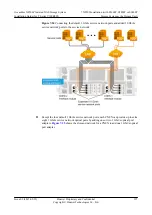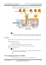
l
Expansion ports on SUC's controller A can connect only to expansion ports on SUD's disk
module A. Expansion ports on SUC's controller B can connect only to expansion ports on
SUD's disk module B.
l
It is advisable to set up more than two expansion loops for two or more SUDs. The number
of SUDs in each expansion loop should be consistent.
l
A mini SAS expansion port on the SUC can connect to a maximum of twelve SUDs. A 4
Gbit/s Fibre Channel expansion port on the SUC can connect to a maximum of five SUDs.
l
The interface modules that connect to the configuration disk enclosure (the disk enclosure
with coffer disks) must be inserted in slot A0 and slot B0 in the controller enclosure.
l
P0 ports of the interface modules in slot A0 and slot B0 must connect to the PRI expansion
ports of the configuration disk enclosure (the disk enclosure with coffer disks).
l
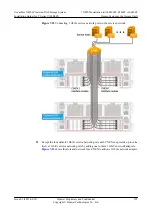
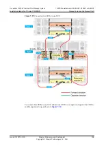
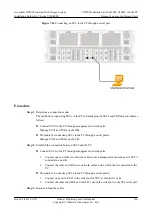
In the expansion loop that contains more than one SUDs, SUC's controllers A and B connect
to SUDs in opposite directions. The positive direction goes from SUC's controller A, port
PRI on the first SUD's disk module A, port EXP on the first SUD's disk module A, to port
PRI of the adjacent SUD's disk module A, and so on. The negative direction goes from
SUC's controller B, port PRI on the last SUD's disk module B, port EXP on the last SUD's
disk module B, to port PRI on the adjacent SUD's disk module B, and so on.
l
The radius of optical fibers must be larger than 5 mm. The radius of mini SAS cables must
be larger than 15 mm. Reserve a clearance larger than 97 mm for wiring.
l
The expansion port types of SUDs in the same storage system must be consistent (expansion
ports are all SAS expansion ports or Fibre Channel ports).
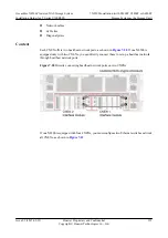
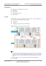
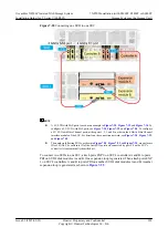
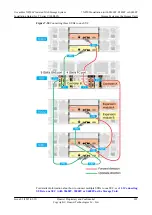
The S5600T, S5800T or S6800T fully loaded with expansion cards is used as an example. The
expansion card locations displayed in the following figure may differ slightly from the actual
locations. For details on the rules of inserting expansion cards, see
The Expansion Network Adapter to The SUC When The S5600T, S5800T or S6800T Is
Configured
NOTE
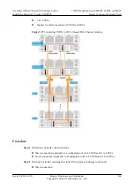
SUD1 refers to the configuration disk enclosure (the disk enclosure with coffer disks). P0 ports of the
interface modules in slot A0 and slot B0 must connect to the PRI expansion ports of SUD1.
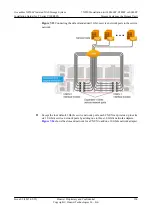
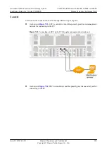
To connect one SUD to one SUC, attach ports EXP 0 on SUC's controllers A and B to ports PRI
on SUD's disk modules A and B. Then an expansion loop is generated, as shown in
.
OceanStor N8500 Clustered NAS Storage System
Installation Guide (for T Series V100R005)
7 N8500 Installation (with S5600T, S5800T or S6800T
Storage System as the Storage Unit)
Issue 02 (2015-09-22)
Huawei Proprietary and Confidential
Copyright © Huawei Technologies Co., Ltd.
202

