


3.
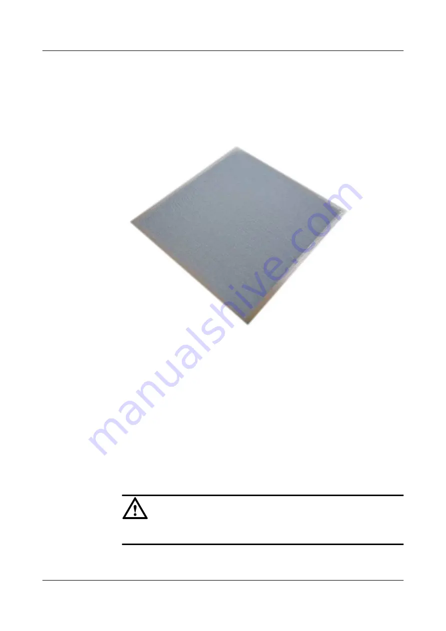
Use a clean card to smear the thermal compound over the center of the CPU.
The thermal compound layer is as thick as a piece of common paper.
shows
the smeared thermal compound layer. Ensure that the thermal compound is evenly and
fully painted.
Figure 6-30
Smeared thermal compound layer
Step 9
Assemble the CPU and heat sink.
1.
Determine the installation position of the heat sinks based on the pin density. The heat
sink with low fin density corresponds to CPU 1 and the heat sink with high fin density
corresponds to CPU 2. Do not install the heat sinks reversely.
2.
Align the notched corner on the heat sink with the triangle hold in the carrier, place the
heat sink on the carrier, align all retaining clips with the heat sink, and insert the
retaining clips into the heat sink. See (2) in
. When the retaining clips are
completely inserted, you can hear a click sound.
Step 10
Install the CPU and heat sink.
1.
Remove the CPU protective cap.
NOTICE
Keep the protective cap horizontal to prevent damaging the socket pins.
2.
Shine a light at various angles onto the CPU bonding pad and the CPU socket and check
for bent pins, foreign matter, and bonding pad damage.
FusionServer G5500 Server
User Guide
6 Optional Part Installation
Issue 02 (2017-12-15)
Huawei Proprietary and Confidential
Copyright © Huawei Technologies Co., Ltd.
147


