background image

FusionModule5000 Smart Modular Data Center 
Commissioning Guide 

6 Commissioning the Management System 


Issue 06 (2020-03-20) 

Copyright © Huawei Technologies Co., Ltd. 

58 


Step 3


Click 

Add

 in the 

Email Receiving Settings

 area and enter the receiver's email address. 

Step 4


Click 

Confirm

 to access the re-authentication page. Enter 

Login password

 and click 

Submit

Step 5


Click 

Test

 to check whether the added email address is available. If it is available, 

Successfully to send the test email.

 is displayed. If it is unavailable, 

Failed to send the test 

email.

 is displayed. Check whether the receiver's email parameters are correctly set. 

Step 6


Select 

Add

 on the 

SMS Settings

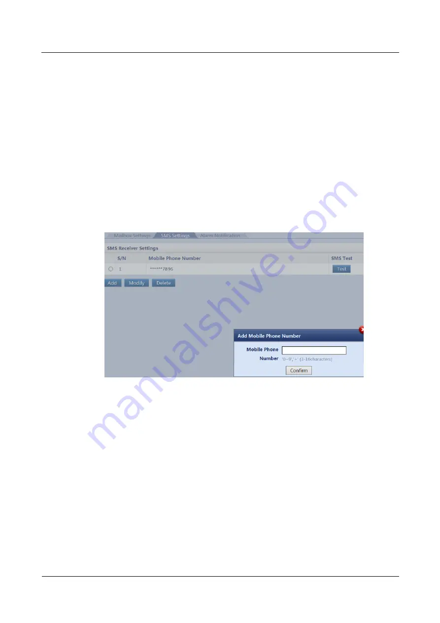
 page and enter the receiver's mobile phone number. 

Step 7


Click 

Confirm

 to access the re-authentication page. Enter 

Login password

 and click 

Submit

Step 8


Click 

Test

 to check whether the added mobile phone number is available. If it is available, 

Successfully to send the test short message.

 is displayed. If it is unavailable, 

Failed to send 

the test short message.

 is displayed. Check whether the receiver's mobile phone parameters 

for receiving short messages are correctly set. 

Figure 6-6


SMS setting page 


Step 9


Set the 

Alarm notification delay time

 and 

Add Alarm Notification

 parameters. 

Summary of Contents for FusionModule5000

Page 1: ...FusionModule5000 Smart Modular Data Center V100R001C03 Commissioning Guide Issue 06 Date 2020 03 20 HUAWEI TECHNOLOGIES CO LTD ...

Page 2: ...tomer All or part of the products services and features described in this document may not be within the purchase scope or the usage scope Unless otherwise specified in the contract all statements information and recommendations in this document are provided AS IS without warranties guarantees or representations of any kind either express or implied The information in this document is subject to c...

Page 3: ...t engineers Symbol Conventions The symbols that may be found in this document are defined as follows Symbol Description Indicates a hazard with a high level of risk which if not avoided will result in death or serious injury Indicates a hazard with a medium level of risk which if not avoided could result in death or serious injury Indicates a hazard with a low level of risk which if not avoided co...

Page 4: ...ssues are cumulative The latest document issue contains all updates made in previous issues Issue 06 2020 03 20 Modified 6 1 Preparations and WebUI Login Issue 05 2019 12 20 Updated the safety information Issue 04 2019 11 29 Updated the password change description Issue 03 2019 03 06 Updated the manual name and so on Issue 02 2018 08 20 Optimized the prerequisites for power management Issue 01 201...

Page 5: ...er On Commissioning Process 18 3 5 Check Before Power On 18 3 5 1 Checking Before Powering On the Integrated Cabling System 18 3 5 2 Checking Before Powering On the Power Supply and Distribution System 19 3 5 3 Checking Before Powering On the Cooling System 19 4 Commissioning the Power Supply and Distribution System 21 4 1 Optional Commissioning the PDB 21 4 2 Powering On the Precision PDC 21 4 3 ...

Page 6: ... 6 3 3 Commissioning the Exit Button Skylight Button Atmosphere Light Emergency Button and Magnetic Lock 77 6 6 4 NetEco Management 78 6 6 4 1 Connecting the Communications Cable 78 6 6 4 2 Setting NetEco Parameters 78 6 6 4 3 Creating an ECC800 on the NetEco 80 6 6 5 Video Management 81 6 6 5 1 Networking Scenarios 81 6 6 5 2 Commissioning a Camera Smart ETH Gateway Networking Scenario 82 6 6 5 2...

Page 7: ... 7 1 7 How to Manage WebUI Users 112 7 1 8 Creating a Smart Module Plan View 113 7 1 9 How Can I Change the ECC800 IP Address on the WebUI 115 7 1 10 How Do I Configure ECC800 Alarm Parameters 116 7 1 11 How Is a Signal Name Changed 117 7 1 12 How Should I Link the Smoke Alarm with the Alarm Beacon over the ECC800 WebUI 117 7 1 13 How should I Link the AI DI Alarm with the Alarm Beacon over the EC...

Page 8: ... operating or maintaining the equipment The safety instructions in this document are only supplements to local laws and regulations Huawei will not be liable for any consequences of the following circumstances Operation beyond the conditions specified in this document Installation or use in environments which are not specified in relevant international or national standards Unauthorized modificati...

Page 9: ...conductor surface or terminal measure the contact point voltage and ensure that there is no risk of electric shock After installing the equipment remove idle packing materials such as cartons foam plastics and cable ties from the equipment area In the case of a fire immediately leave the building or the equipment area and turn on the fire alarm bell or make an emergency call Do not enter the build...

Page 10: ...ith scratches cannot be exposed to an outdoor environment for a long period of time Before operations ensure that the equipment is firmly secured to the floor or other solid objects such as a wall or an installation rack Do not use water to clean electrical components inside or outside of a cabinet Do not change the structure or installation sequence of equipment without permission Do not touch a ...

Page 11: ...are clear of the sources and degree of various potential hazards in equipment installation operation maintenance Trained personnel personnel who are technically trained have required experience are aware of possible hazards on themselves in certain operations and are able to take protective measures to minimize the hazards on themselves and other people Operators operation personnel who may come i...

Page 12: ...ables ensure that a distance of at least 30 mm exists between the cables and heat generating components or areas This prevents damage to the insulation layer of the cables Do not route cables behind the air intake and exhaust vents of the equipment Ensure that cables meet the VW 1 flame spread rating requirements Bind cables of the same type together When routing cables of different types ensure t...

Page 13: ...nment Requirements To prevent fire due to high temperature ensure that the ventilation vents or heat dissipation system are not blocked when the equipment is running Install the equipment in an area far away from liquids Do not install it under areas prone to condensation such as under water pipes and air exhaust vents or areas prone to water leakage such as air conditioner vents ventilation vents...

Page 14: ... away irrelevant personnel Carry the operation machinery and tools properly to prevent them from falling off and causing injuries Personnel involving working at heights are not allowed to throw objects from the height to the ground or vice versa Objects should be transported by tough slings hanging baskets highline trolleys or cranes Ensure that guard rails and warning signs are set at the edges a...

Page 15: ...t is intact and confirm its load bearing capacity Do not overload it Ensure that the ladder is securely positioned The recommended angle for a ladder against the floor is 75 degrees as shown in the following figure An angle rule can be used to measure the angle Ensure that the wider end of the ladder is at the bottom or protective measures have been taken at the bottom to prevent the ladder from s...

Page 16: ...re of unstable or heavy objects on the cabinet Be cautious to avoid injury when moving heavy objects When moving the equipment by hand wear protective gloves to prevent injuries Move or lift the equipment by holding its handles or lower edges Do not hold the handles of modules such as power supply units fans and boards that are installed in the equipment because they cannot support the weight of t...

Page 17: ...to prevent scalds When maintaining or replacing components pay attention to high pressure components such as the compressor and refrigerant pipe to prevent the refrigerant system from being cracked or exploded due to misoperations Refrigerant Frostbite Refrigerant leakage may cause frostbite Take protective measures for example wear antifreeze gloves when handling refrigerant Storage and Recycling...

Page 18: ...ash it immediately with clean water and go to the hospital for medical treatment Use dedicated insulated tools Move batteries in the required direction Do not place a battery upside down or tilt it Keep the battery loop disconnected during installation and maintenance Use batteries of specified models Using batteries of other models may damage the batteries Dispose of waste batteries in accordance...

Page 19: ... use unsealed lead acid batteries To prevent fire or corrosion ensure that flammable gas such as hydrogen is properly exhausted for lead acid batteries Lead acid batteries emit flammable gas when used Ensure that batteries are kept in a well ventilated area and take preventive measures against fire Battery Leakage Battery overheating causes deformation damage and electrolyte spillage When the elec...

Page 20: ...re charging is forbidden at 0 C Low temperature charging may cause crystallization which will result in a short circuit inside the battery Use batteries within the allowed temperature range otherwise the battery performance and safety will be compromised Do not throw a lithium battery in fire When maintenance is complete return the waste lithium battery to the maintenance office 1 8 Others Exercis...

Page 21: ...plete the commissioning of the customer s power supply and distribution devices The initial configuration parameters are essential to the reliable running of all systems Improper modifications of parameters will cause abnormal running status or even damage to the systems Before power on commissioning verify that the aisle temperature is within a normal operating range Power on the primary route an...

Page 22: ...be familiar with the configurations of the power supply and distribution system cooling system and management system as well as the operations for each core component and must gain the qualification from Huawei Construction personnel Must have the electrician certificate and welder certificate 3 2 Tools To ensure smooth power on commissioning prepare the tools listed in the following table Insulat...

Page 23: ...2020 03 20 Copyright Huawei Technologies Co Ltd 16 Tools Multimeter Electroprobe Network cable tester Cable tie PVC insulation tape Marker Electrostatic discharge ESD gloves Step ladder ESD wrist strap Clamp meter Point thermometer Adjustable wrench RJ45 crimping tool Wire stripper Torque wrench Mobile light NA NA ...

Page 24: ...Figure 3 1 System network diagram If four or more cameras are deployed in a single smart module or multiple smart modules share one VCN connect the signal cable from each camera and VCN to the LAN switch Wireless communication is automatically established after the access actuator skylight actuator and multi functional sensor successfully connect to and communicate with the ECC800 through PoE ...

Page 25: ...re powering on the integrated cabling system Check Item Operation Expected Result Cable connections Check the cable connections Check the ground cable connection Cables are securely bound and connected Cables are connected to correct ports The resistance between each cabinet ground point and the equipment room ground bar is less than 0 1 ohm Phase sequence Check the colors and labels of upstream a...

Page 26: ...an SPD indicator is green the SPD is running properly If an SPD indicator is red the SPD is faulty and must be replaced immediately Circuit breaker status Check the circuit breaker labels Check the circuit breaker status Circuit breaker labels are correct clear complete and attached properly All circuit breakers in the integrated UPS are OFF Short circuit Conduct input and output short circuit det...

Page 27: ...wei Technologies Co Ltd 20 Check Item Operation Expected Result connections signal cables Check the communications cable connection to the ECC800 requirements Smart cooling product pipe connections Check the pipe connections to air cooled smart cooling products The pipes are properly installed and the thermal insulation layers are intact ...

Page 28: ...the range of 342 456 V Measure the upstream input frequency using a multimeter Frequency range for the 50 Hz scenario 47 53 Hz Frequency range for the 60 Hz scenario 57 63 Hz 4 Turn on the input switch in the PDB Step 2 Optional Switch on the light output circuit breaker in the PDB and check that the PWR indicator on the AC actuator lights up press the light button to power on lights Step 3 Switch...

Page 29: ...e MDU screen displays and communicates properly After the first login change the password in time to ensure account security and prevent unauthorized network attacks such as data tampering Huawei will not be liable for any security issues caused by your failure to change the preset password in time or password loss after changing After login you are allowed to perform operations until being logged...

Page 30: ...5 Switch on the network cabinet output circuit breaker in the PDC and switch on the rPDU input circuit breaker in the network cabinet to power on the network cabinet Step 6 Switch on the IT cabinet output circuit breakers in the PDC one by one and switch on the rPDU input circuit breaker in the IT cabinet to power on the IT cabinet While switching off output circuit breakers check that their mappi...

Page 31: ...o power on lights Step 3 Optional Switch on the air conditioner output circuit breaker in the power distribution unit of the smart busway to power on the air conditioner Step 4 Switch on the network cabinet output circuit breaker in the power distribution unit of the smart busway and switch on the rPDU input circuit breaker in the network cabinet to power on the network cabinet Step 5 Switch on th...

Page 32: ...bution cabinet and the AC1 and AC2 switches on the smart cooling product Step 2 After the system is powered on for the first time the Quick Settings screen is displayed Log in as the admin user as shown in Figure 5 1 Figure 5 1 Initial power on Table 5 1 Preset password User Preset Password Permission Description admin administrator user 000001 People can operate all menus operator common user 000...

Page 33: ...on Only certified pros are allowed to modify the advanced parameters Unauthorized modifications may lead to device malfunction or damage After the first login change the password in time to ensure account security and prevent unauthorized network attacks such as data tampering Huawei will not be liable for any security issues caused by your failure to change the preset password in time or password...

Page 34: ... parameter according to the actual situation Teamwork Settings visible for V200R002 version Teamwork group No Set the assigned teamwork control number The number of the teamwork controlled group which is the same for all the devices in the group Air conditioner address Set the assigned unit address Air conditioner addresses should be different from each other Teamwork function Disable or enable th...

Page 35: ...st will become the standby ones System Settings visible for V200R002 version Humidifying function The humidifying function can be set to Enable Disable or Enabled when active power Enable indicates that the electric humidifier will be started when the ambient humidity is lower than the certain humidity range of the humidity set point Disable indicates that the electric humidifier will not be start...

Page 36: ... you are advised to choose Cold aisle if the cold aisle T H sensors are configured and choose Supply air if the cold aisle T H sensors are not configured When the application scenario is non aisle containment you are advised to choose Return air and choose Cold aisle if the cold aisle T H sensors are configured Hot aisle is not recommended Temperature control mode This parameter controls the tempe...

Page 37: ...nd the humidity value under this type are set the device conducts humidifying or dehumidifying based on the settings Set this parameter as required 40 60 RH recommended Cold aisle sensor 1 Cold aisle sensor 2 Cold aisle sensor 3 Cold aisle sensor 4 Cold aisle sensor 5 The sensors in cold aisles can be set to Enable or Disable The cold aisle sensors outside the cabinet need to be enabled when they ...

Page 38: ...ttings Comm Settings IP Settings Step 2 Set IP assigning mode to DHCP Automatic If IP assigning mode is set to DHCPAutomatic the values of IP address Subnet mask and Gateway are automatically assigned End 5 3 Setting Temperature and Humidity Values and Optional Enabling T H Sensors Prerequisites The T H sensors outside the cabinet need to be enabled when they are installed otherwise skip Step 2 If...

Page 39: ...en the application scenario is cold or hot aisle containment you are advised to choose Cold aisle if the cold aisle T H sensors are configured and choose Supply air if the cold aisle T H sensors are not configured When the application scenario is non aisle containment you are advised to choose Return air and choose Cold aisle if the cold aisle T H sensors are configured Hot aisle is not recommende...

Page 40: ...ing or heating based on the settings Set this parameter as required Return air temperature 26 35 C recommended Supply air temperature 18 24 C recommended Cold aisle temperature 18 24 C recommended Hot aisle temperature 26 35 C recommended Control point humidity setpoint After the Temperature and humidity control type and the humidity value under this type are set the device conducts humidifying or...

Page 41: ... operations accordingly If the differential pressure sensor is not installed skip this part Procedure Step 1 On the home screen choose Settings System Settings Indoor fan set Air side difference pressure sensor type to 0 50 Pa Step 2 Set Indoor fan control type to Pressure diff ctrl Step 3 Change the other parameters based on the following instructions Table 5 4 Parameter description Parameter Des...

Page 42: ... Sets the maximum speed for the indoor fan You are advised not to change the value End 5 5 Setting Teamwork Control Parameters Prerequisites Assign teamwork group number and teamwork unit address for the teamwork controlled smart cooling products as follows Teamwork group no Group the smart cooling products in adjacent areas as one that is assign one teamwork group number for them At most four tea...

Page 43: ...ration Principle Default Value Teamwork group No Set the assigned teamwork control number The number of the teamwork controlled group which is the same for all the devices in the group 1 Air conditioner address Set the assigned smart cooling product address Smart cooling product addresses should be different from each other NA Enable Teamwork CAN resistor Indicates the build out resistor status of...

Page 44: ...ode For V200R002 version the software will not restart when the networking mode is changed Networked over CAN or MAC_CAN CAN network indicates teamwork control over a CAN bus MAC_CAN network teamwork control over an FE port MAC_CAN network Number of smart cooling products in this group Number of the smart cooling products in this group 1 to 32 can be set Total number of the smart cooling products ...

Page 45: ...Disable the master device does not synchronize data to the slave device and all the smart cooling products operate based on their own requirements not referring to the mode delivered by the master device When the requirement control is Anti competitive running the master device synchronizes data the temperature and humidity control type and set points of the master device and other parameters to t...

Page 46: ...all the smart cooling products by performing Step 1 and Step 2 Step 4 On the home screen of any teamwork controlled smart cooling product tap If the teamwork control succeeds the teamwork topology of the smart cooling product in the group is displayed as shown in Figure 5 6 Table 5 6 describes the note for the screen Figure 5 6 Teamwork topology Table 5 6 Notes for the screen No Parameters Note 1 ...

Page 47: ...e with green frame indicates the device itself as shown in A non green frame indicates the other device in the group as shown in 6 Ground color red bright gray Red indicates that a critical alarm is generated as shown in Bright gray indicates that the device is operating without any critical alarms as shown in If teamwork succeeds the teamwork icon is green If teamwork fails the teamwork icon is r...

Page 48: ...s the check is complete If no check the cable connection and the settings of teamwork control parameters 5 6 Optional Setting WIFI Parameters Prerequisites After connecting the WIFI module of the USB interface to the USB port of the smart cooling product display WIFI Settings is enabled to be set Procedure Step 1 On the home screen choose Settings Comm Settings WIFI Settings Step 2 Set the paramet...

Page 49: ... Step 1 Tap Start on the home screen of the ACC If the screen shown in Figure 5 7 is displayed indicating initial startup perform Step 2 for initial startup verification Figure 5 7 Initial startup Figure 5 8 Password screen If the software version is after V200R002C00SPC050 a QR code will generate in the Start Password page used for inputing the barcode and verify code when offline boot is used If...

Page 50: ...erence only For offline boot enter the barcode and the verification code on the mobile phone app The app automatically generates a startup password for the smart cooling product Then enter the password on the home screen of the ACC to start the smart cooling product For online boot activate the startup password on the mobile phone app to start the smart cooling product If the initial startup verif...

Page 51: ...t of BarCode After clicking it and scanning the QR code generated in the Start Password page the barcode and verify code can be automatically entered into the APP Step 4 On the Offline Activation screen enter Bar code and Verification code which are available on the home screen Tap Generate PWD to generate a startup password If startup verification fails when you do not enter the password within 5...

Page 52: ...uct WiFi and ensure proper communications between the mobile phone app and the smart cooling product Step 4 Open the Service Expert app Step 5 Tap StartUp on the home screen of the app and the screen shown in Figure 5 12 is displayed Figure 5 12 Login screen The preset user name is admin and the preset password is Changeme If you change the login password on the smart cooling product LCD the passw...

Page 53: ...ling product Figure 5 13 Online boot Step 8 Tap OK and follow instructions as prompted on the screen until the success message for the startup is displayed on the screen End 5 8 Startup Wizard Context The startup wizard allows for commissioning of components such as the fan humidifier and chilled water valve It also supports component automatic operation and automatic device checking and can outpu...

Page 54: ... Maint Wizard Startup as shown in Figure 5 14 Figure 5 14 Startup wizard For the initial startup wizard Last record is in grey indicating that the operation is not allowed For the non initial startup wizard choose Last record and you can view the last startup wizard report Step 2 Tap Yes The checking before startup screen is displayed as shown in Figure 5 15 Figure 5 15 Checking before startup Ste...

Page 55: ... selected by default if you first enter the screen where you select commissioning items Except that the indoor fan item is mandatory you can clear other commissioning items that are not required Step 5 Tap Yes The component startup commissioning screen is displayed as shown in Figure 5 17 Figure 5 17 Fan commissioning The fan commissioning item is mandatory After commissioning for a component succ...

Page 56: ...ils which ends startup wizard commissioning Figure 5 19 Commissioning unsuccessfully If commissioning fails tap Commissioning failed in Figure 5 19 to view the details End 5 9 Optional Power off Context In shutdown mode the Shutdown button is green unavailable and the Start button is gray available Procedure Step 1 Tap Shutdown on the home screen A warning is displayed indicating whether to shut d...

Page 57: ...2 Step 4 Optional If the smart cooling product needs to be maintained in power off mode or long term power off turn off the smart cooling product switch in the PDC If the NetCol5000 C will be idle for a long time ensure that the circulation water inside the system has a temperature no lower than 3 C or has used antifreeze liquid otherwise the heat exchanging pipes of the smart cooling product may ...

Page 58: ...0 Table 6 1 Default IP addresses for the WAN and LAN ports on the ECC800 Port Default IP Address WAN_1 192 168 1 10 WAN_2 192 168 0 10 LAN_1 and LAN_2 192 168 248 10 The WAN_1 port IP address cannot be set to an IP address in any of the following network segments 192 168 0 x 192 168 8 x 192 168 248 x and 192 168 245 x IP addresses for the WAN_1 and WAN_2 ports should not be set in the same network...

Page 59: ...tep 3 Set LAN parameters If the ECC800 connects to a LAN and a proxy server has been selected perform Step 3 3 and Step 3 4 If the ECC800 connects to the Internet and the PC in a LAN accesses the Internet over a proxy server do not perform Step 3 3 and Step 3 4 Otherwise you will fail to access the ECC800 1 Open the Internet Explorer and choose Tools Internet Options 2 Click the Advanced tab and s...

Page 60: ... Ltd 53 Figure 6 1 Setting internet options Step 4 Set Internet Explorer parameters 1 When you use Internet Explorer for access set Internet Explorer to ensure the normal display of and operations on the WebUI Choose Tools Compatibility View and add the web access address to the compatibility view 2 Add the ECC800 IP address to the list of trusted sites ...

Page 61: ...6 2 Adding an address 3 Enable file download and set the security level of the trusted site to low Figure 6 3 Setting parameters When switching between different versions of the ECC800 on your PC you are advised to clear the historical Internet Explorer cache Failing to do so may cause some information missed or exception after login The following provides the details ...

Page 62: ... password Changeme set the language and click Log In After the first login change the password in time to ensure account security and prevent unauthorized network attacks such as data tampering Huawei will not be liable for any security issues caused by your failure to change the preset password in time or password loss after changing An account is logged out due to timeout if no operation is perf...

Page 63: ...s normal enter the Checker Name and Check Date and click Configuration Completed To export the configuration result click Export Check Result The export file format is csv End 6 3 Commissioning Alarm Notification You can set alarm notification by email or SMS as required Information about a maximum of 20 users who will receive alarm notification can be displayed Prerequisites To implement alarm no...

Page 64: ...parameters on the sender s email configuration page Email Type Email Server Domain Name Mailbox Server IP Address Encryption Mode and SMTP port Remarks Sina Mail smtp sina com How to obtain 1 Click Start on the PC enter cmd in Running area and click Search to access the administrator page 2 Enter ping email server domain name at the position of the blinking cursor and press Enter to obtain email s...

Page 65: ...to send the test email is displayed Check whether the receiver s email parameters are correctly set Step 6 Select Add on the SMS Settings page and enter the receiver s mobile phone number Step 7 Click Confirm to access the re authentication page Enter Login password and click Submit Step 8 Click Test to check whether the added mobile phone number is available If it is available Successfully to sen...

Page 66: ...9 Figure 6 7 Setting the Alarm notification delay time parameter Figure 6 8 Adding alarm notification Mailbox Address in Alarm Notification can be selected after it is added in Mailbox Settings Mobile Phone Number can be selected after it is added in SMS Settings Step 10 Click Confirm to access the re authentication page Enter Login password and click Submit ...

Page 67: ...tion units otherwise a false alarm may be generated Procedure Step 1 Set parameters for general input units on the ECC800 WebUI 1 Set parameters for general input unit 1 Table 6 3 Power distribution settings for a general input unit Path Parameter Name Default Value Setting Monitoring Power Distribution General Input Unit1 Running Parameters Power Distribution Settings Rated system frequency 50 Se...

Page 68: ...ose Monitoring Power Distribution Power Distribution Unit 1 Display Configuration select Running Information Display and Running Parameters Display corresponding to QF1 and QF2 and then tap Submit 3 Configure the power distribution settings for power distribution unit 1 Table 6 4 Power distribution settings for a power distribution unit Path Parameter Name Default Value Description Monitoring Powe...

Page 69: ...nd then off for 0 05 seconds The ECC800 enters the wireless networking 802 15 4 pairing status 2 Hold down the BLINK button on the AC actuator for 2 seconds 1 5 seconds allowed The RF_Z indicator on the AC actuator turns from steady green to blinking green intermittently at super short intervals blinking at super short intervals for 0 5 second and then off for 0 5 second The component enters the w...

Page 70: ...unning Parameters set Set light mode is Manual 2 Choose Controls select Light control select ON and click Submit The light is on When the light is normal set Set light mode to Automatic Path Monitoring Aisle AC Actuator Group AC Actuator End 6 6 Feature Commissioning Certain features described in this chapter have been commissioned in the Opening Guide so you can skip them based on the actual situ...

Page 71: ...this example the fire controller connects to port AI DI_6 The actual port prevails Linkage Grouping Table 6 7 Linkage grouping Linkage Category Default Status Function Link smoke alarm with skylight open Link smoke alarm with door open on If a smoke alarm is raised the smart module opens the skylights and access control by default Link smoke alarm with air conditioner off Link smoke alarm with lig...

Page 72: ...ntroller and ECC800 Step 2 Log in to the ECC800 WebUI as an administrator Step 3 Set the Linkage Group status Figure 6 10 Setting the Linkage Group status Select Link fire control with smart cooling product off under Linkage Group If its value is on the corresponding logic configurations under Linkage Logic List are available If its value is off the corresponding logic configurations under Linkage...

Page 73: ...en or Normal Close as required After the corresponding AI DI device is enabled the AI DI device type must be consistent with the DO state Table 6 8 Fire sensor NO and NC definitions Item Definition NO Dry contact signal for the fire sensor abnormality alarm Closed alarm open normal NC Dry contact signal for the fire sensor abnormality alarm Closed normal open alarm 4 Ensure that Fire power supply ...

Page 74: ...he ECC800 from the WebUI to the app and displays the data on the app screen The ECC800 connects to the NetEco over a northbound port and can upload the calculated PUE and power consumption data to the NetEco PUE Calculation Formula The PUE ranges from 1 to 3 If the PUE value is greater than or equal to 3 the value is displayed as 3 When the PUE value is 1 it is invalid Table 6 9 PUE calculation fo...

Page 75: ...rical energy and Statistics Mode to Hour set other query criteria such as Start time and End Time as required and click Query Record the increment in total system input electrical energy of the ECC800 Increment in total system input electrical energy 110 0 kWh 100 0 kWh 10 0 kWh Figure 6 12 Querying the total system input electrical energy 3 Set Device to ECC800 Performance data to Total electrica...

Page 76: ...0 WebUI as an administrator Step 2 Choose System Settings PUE Configuration Step 3 Ensure that PUE function is set to Enable Step 4 Set PUE configuration mode to User defined and click Submit 1 On the Total Power Consumption Configuration tab page click Add to enter the Total Power Consumption Configuration page On the Select Device tab page select Integrated PDU 1 On the Select Indicators tab pag...

Page 77: ... 4 99 with two significant digits The default value is 1 00 The multiple is configured for slightly adjusting the calculated PUE ensuring that the calculated PUE is as close as possible to the actual PUE Step 5 Calculate the PUE of the smart module PUE Increment in the total active electricity energy of the device input Increment in the total power consumption of the branch IT load output Performa...

Page 78: ...rformance Data to view historical PUE data 1 Choose Device Performance data Start time End Time and the display mode table or curve of the PUE parameter as required 2 Click Query The 17 00 00 data includes the data from 17 00 00 to 18 00 00 If the query time is between 18 00 00 and 19 00 00 and the time has not arrived at 19 00 00 yet then the displayed time is 18 00 00 and the data includes the d...

Page 79: ...t the door status sensor parameters Table 6 11 Parameter settings Setting area Object Method AI DI_1 Port Settings Front door status AI DI_1 1 Choose AI DI_1 sensor to Enable click Submit 2 Set AI DI_1 sensor type to Door sensor click Submit AI DI_2 Port Settings Rear door status AI DI_2 1 Choose AI DI_2 sensor to Enable click Submit 2 Set AI DI_2 sensor type to Door sensor click Submit Step 2 Che...

Page 80: ... page On the Basic Info tab page enter User name and Employee ID Specify the following information on the Password tab Password Enter and confirm the password Card number The card number can be recorded directly or by swiping the card Record directly Type the access card number in the text box Record by swiping the card Click Swipe Card and place the card on the access control device The card numb...

Page 81: ...rd Fingerprint Card and password Card and fingerprint Fingerprint and password or Card password and fingerprint For example if you select Card password and fingerprint for the authorization mode the door can be opened only after you swipe an authorized card first enter the authorized password press to confirm the password and then scan the fingerprint The fingerprint information is used only for c...

Page 82: ... access management settings 4 On the Authorization Operations tab page click Synchronize to Device select the modified access control devices and click Start Synchronization Figure 6 21 Synchronizing access permissions 5 When Synchronization Status is Synchronized for the related devices close the Synchronize Access Permission page Step 2 Set an alarm for card readers Set Logical level configurati...

Page 83: ...arm for Logical level configuration for reader removed Step 3 Check the functions of the access control device and access actuator Table 6 14 Function check Check Method Normal Connection Status Method 1 Attempt to open the door using the configured authentication mode Method 2 On the WebUI choose Monitoring Aisle Access Actuator Group Access Actuator n and click Controls to open the door remotely...

Page 84: ...d The aisle door is opened successfully Step 2 Check functions of the skylight button Table 6 17 Function commissioning Check Method Normal Connection Status Attempt to open the door by pressing the skylight button when the aisle door is closed The skylight can be opened manually Step 3 Check functions of the atmosphere light Table 6 18 Function commissioning Check Method Normal Connection Status ...

Page 85: ...lly closed check whether there is a door open alarm on the ECC800 There is no door open alarm on the ECC800 If a door open alarm is reported when the door is closed relocate the magnetic lock and magnet to minimize the deviation until the door open alarm is cleared End 6 6 4 NetEco Management 6 6 4 1 Connecting the Communications Cable Procedure Step 1 Connect the communications cable to the WAN_1...

Page 86: ...eter based on the default gateway address assigned by the network administrator Step 3 Click Submit Step 4 Set NetEco communications parameters on the ECC800 WebUI Table 6 22 NetEco parameters Path Parameter Default Value Setting System Settings NMS Application NetEco Communicati on Parameters Server IP 192 168 8 1 1 IP address of the primary NetEco server NOTE The NetEco IP address and the ECC800...

Page 87: ...client by web browser You have created modules or container in Data Center Planning Context For detailed operations see iManager NetEco 6000 Device Installation and Commissioning Guide of the corresponding version Procedure 1 Choose System Configuration Management Data Center Planning from the main menu The Data Center Planning window is displayed 2 Click in the upper left area of the Data Center ...

Page 88: ...ress window During binding of the ECC800 for the first time the screen will be locked indefinitely when the progress bar reaches 30 and displays Loading device profile Please try it later The actual operation results prevail 6 6 5 Video Management 6 6 5 1 Networking Scenarios Smart ETH Gateway Networking Scenario There are multiple VCNs for multiple smart modules you are advised to evenly distribu...

Page 89: ...meras to each VCN Figure 6 25 Camera VCN connecting to the LAN switch 6 6 5 2 Commissioning a Camera Smart ETH Gateway Networking Scenario If the camera web version is IPC V200R003C00 refer to this topic to commission the camera 6 6 5 2 1 Commissioning IPC6325 Cameras Prerequisites If multiple cameras are accessed retain the connection of one camera and disconnect connections from other cameras Af...

Page 90: ...8 199 Camera external IP address VCN Example 192 168 248 55 range 192 168 248 50 192 168 248 199 VCN external IP address Procedure Step 1 Connect a network cable between the PC network port and the LAN_1 port protected by a security mechanism on the ECC800 Step 2 Set the IP address for the IPC6325 camera 1 Enter https 192 168 248 10 in the address box of the browser and press Enter to access the W...

Page 91: ... Adding video information 4 Select the required camera and click the link under Link PC IP address and camera external IP address should be in the same network segment to access and log in to the camera WebUI Enter the preset user name admin and preset password HuaWei123 and click Login 5 Optional Choose Settings Basic Configuration Network Parameters set Way to obtain IP to Use the following IP a...

Page 92: ...reparing Documentation section 1 Preview the site situation in real time and check the camera coverage through videos Adjust the lens if necessary 2 Optional If you use the SD card when no VCM500 is configured perform commissioning by following the instructions in 6 6 5 2 2 Commissioning IPC6325 Camera SD Card Configured 3 Choose Settings Video Audio Image Video Settings and set IP address Subnet ...

Page 93: ...ng to this section 6 6 5 2 2 Commissioning IPC6325 Camera SD Card Configured Context If the VCN is not configured and an SD card is chosen perform the following procedure Procedure Step 1 Log in to the Huawei IPC WebUI Step 2 Format the SD card 1 Choose Settings System Configuration Storage Management 2 The Storage Management page is displayed Format the SD card Step 3 Set the camera stream type a...

Page 94: ...onger time video storage is required set camera parameters according to the following table Table 6 25 Camera configuration parameters Condition Result Coding Protocol Resolution Frame Rate I frame Interval Minimum Required Bit Rate Supported Video Storage Duration h H 265 1080P 25 50 1M 66 H 264 1080P 25 50 1M 66 H 265 720P 25 50 0 8M 75 H 264 720P 25 50 1M 66 H 265 720P 25 50 0 6M 105 H 264 720P...

Page 95: ... through the WebUI Support Windows 7 Internet Explorer 8 9 10 11 Chrome 32 and FireFox 35 51 Support Windows 8 Internet Explorer 10 11 Chrome 32 and FireFox 35 51 Support Windows 10 Internet Explorer 11 Chrome 32 and FireFox 35 51 Google Chrome 45 or later versions need to install the Internet Explorer tab plug in Only 32 bit web browsers are supported 2 Enter the preset user name admin and the pr...

Page 96: ...lar Data Center Commissioning Guide 6 Commissioning the Management System Issue 06 2020 03 20 Copyright Huawei Technologies Co Ltd 89 Figure 6 31 Setting primary stream parameters Figure 6 32 Setting secondary stream 1 parameters ...

Page 97: ...net Explorer and press Enter 2 Enter the preset user name admin and the preset password HuaWei123 and click Log In Step 2 For details about how to commission cameras and set parameters for them see the documentation delivered with the equipment or obtain the documentation by referring to the Preparing Documentation section 1 Preview the site situation in real time and check the camera coverage thr...

Page 98: ...Co Ltd 91 Figure 6 34 Setting audio and video parameters If longer time video storage is required set camera parameters according to the following table Table 6 26 Camera configuration parameters Condition Result Coding protocol Resolution Frame rate I frame interval Minimum required bit rate Supported video storage duration h H 265 1080P 25 50 1M 66 ...

Page 99: ...configuration see Configuration Guide The version number is subject to the Quick Start delivered with the VCN The description and link in this document are for reference only Context A default IP address has been configured for the VCN before delivery Modify the IP address based on the actual network plan Procedure Step 1 Modify the IP address for the VCN 1 Configure the PC IP address and the VCN ...

Page 100: ...ples The actual values prevail Set NAT IP to VCN external IP address which is the same as the external IP address mapped from the VCN internal IP address displayed on the ECC800 4 Configure the NTP synchronization After setting The NTP clock source server to Yes set the IP address of the NTP server The server that connects to cameras needs to enable the camera NTP synchronization function For the ...

Page 101: ...to the OMU Portal system Optional Deploying IVS in Stack Mode For details log in to the https e huawei com search for the VCN product documentation open the documentation and see the section Optional Deploying IVS in Stack Mode Optional Deploying MPUs in Cluster Mode For details log in to the https e huawei com search for the VCN product documentation open the documentation and see the section Opt...

Page 102: ...n extranet and the VCN is on a LAN set Server IP address to the VCN external IP address If the VCN software version is V100R003 or later the default user name is admin If the VCN software version is V100R002 or earlier the default user name is Admin 4 Click Log In to access the client home page After the first login change the password in time to ensure account security and prevent unauthorized ne...

Page 103: ...ick Server Recording Plan 2 Select the camera on the Cameras list and click Next 3 Optional Set recording parameters and click Next 4 Set recording plan parameters in the Time settings Drag the timeline to select the time segment for implementing video recording If you set the recording plan policy is to All you do not need to set the recording plan time 5 Click Next to complete the recording plan...

Page 104: ...isites Power distribution devices such as the integrated UPS integrated PDF and precision PDC are successfully connected to the ECC800 The smart module plan view has been created Context IT cabinets network cabinets and smart cooling products support power management The ECC800 connected to an IT cabinet is used as an example in this section Procedure Step 1 Log in to the ECC800 WebUI as an admini...

Page 105: ...d Rated cabinet power as required The settings in the following table are used as examples to describe the basic configuration Table 6 28 Basic configuration Parameter Setting Description Device Name IT Cabinet 101 Set based on the actual device name Cabinet height 42 U space quantity of the cabinet Power Distribution Parameter Settings Power system Single phase Set single phase or three phase bas...

Page 106: ...ioning Guide 6 Commissioning the Management System Issue 06 2020 03 20 Copyright Huawei Technologies Co Ltd 99 Parameter Setting Description 2QF10 L1 the branches for subsequent cabinets are 1QF9 L3 2QF9 L3 and the like Figure 6 39 Power configuration ...

Page 107: ...ble connection Select the branch output configuration and set corresponding parameters for other power distribution devices based on the actual cable connection Step 6 Click Exit Edit Mode to exit the view editing page of the smart module Step 7 Choose Monitoring Cabinet and set Cabinet load factor overhigh alarm threshold default value 90 on the Running Parameters page If the default value is use...

Page 108: ...roducts number of started smart cooling products with the valid maximum cooling capacity received by the ECC800 is greater than or equal to the Number of running air conditioners in this group in Teamwork settings of smart cooling products Context Only for water cooled smart cooling product After the smart cooling product is successfully connected to the ECC800 the cooling capacity management func...

Page 109: ...ecommended supplywater temperature statistics cycle Figure 6 43 Setting cooling capacity management parameters End 6 6 7 2 Querying Cooling Capacity Parameters Prerequisites The chilled water smart cooling product is successfully connected to the ECC800 Procedure Step 1 Log in to the ECC800 WebUI as the administrator Step 2 Choose Monitoring Cooling to access the Running Info page Step 3 Query the...

Page 110: ... Cooling capacity parameters Step 4 Choose Monitoring System Click Cooling Capacity Information on the Running Info tab page to query the cooling capacity parameters of the smart module Step 5 If the cooling load factor of the smart module exceeds 95 a cooling margin insufficient alarm will be raised which will be cleared when the cooling load factor is smaller than 93 End ...

Page 111: ...nsor Group Multi Func Sensor1 Running Parameters ensure that Smoke enable and Temp enable are set to Enable set High temperature alarm threshold and other parameters as required and then click Submit If multiple multi functional sensors are connected commission one multi functional sensor first and then commission the other multi functional sensors in the same way Step 2 Check the functions of the...

Page 112: ...partment through the hole in the side of the multi functional sensor CAUTION Do not generate open flame and ensure that smoke does not damage any device When testing the smoke detection function of the multi functional sensor do not start the smart cooling product or fan because the air from the smart cooling product or fan will interfere with the smoke and therefore affect the detection result Af...

Page 113: ...o configure it Prerequisites One end of the straight through cable has been connected to the RJ45 port on the WLDS900 water sensor and the other end has been connected to the AI DI port on the ECC800 Context To use the AI DI sensor enable the corresponding AI DI port and name the sensor The specific alarm then can be reported If the sensor is prefabricated only check its settings The actual value ...

Page 114: ... that Leak power supply is Yes Step 2 Check functions of water sensors Table 7 2 Function check Check Method Normal Connection Status Alarm Clearance Method Immerse the water detection cable in water Leak DI alarm is generated on the active alarm screen of the app or on the WebUI Wipe dry the water detection cable The alarm disappears automatically End 7 1 3 How to Set and Add the Smoke Detector C...

Page 115: ...administrator 2 Choose Monitoring Aisle Skylight Actuator Group Skylight Actuator 1 Running Parameters DI1 alarm level 3 Set DI1 alarm level to Low voltage alarm or High voltage alarm and click Submit Set DI1 alarm level to Low voltage alarm if the smoke sensor is connected over NO Set DI1 alarm level to High voltage alarm if the smoke sensor is connected over NC Step 2 Check the monitoring functi...

Page 116: ...the current cabinet temperature End 7 1 5 How to Set and Add the T H Sensor BOM Number 33010346 If a T H sensor is installed perform the following steps to configure it Prerequisites One end of the straight through cable has been connected to the RJ45 port on the temperature sensor and the other end has been connected to the COM port on the ECC800 Procedure Step 1 Set the T H sensor device address...

Page 117: ...ot connect to the ECC800 properly check whether the cable between the T H sensor and the ECC800 is connected properly whether the T H sensor and ECC800 are running properly and whether the input parameters are consistent with the T H sensor parameters Step 3 Check functions of the T H sensor Table 7 7 Function check Check Method Normal Connection Status Check the running information about the T H ...

Page 118: ... OFF 2 OFF ON OFF OFF OFF OFF 3 ON ON OFF OFF OFF OFF 4 OFF OFF ON OFF OFF OFF Step 2 Add a T H sensor 1 Log in to the ECC800 WebUI as an administrator 2 Add a T H sensor Table 7 9 Adding a T H sensor Path Parameter Name Setting Choose System Settings Device Management and click Add Device The parameters for adding devices are displayed Device attribute Select Sensor from the drop down list box De...

Page 119: ...T H Sensor Group T H Sensorn Running Parameters and set High temperature alarm threshold Low temperature alarm threshold High humidity alarm threshold and Low humidity alarm threshold as required NOTE The default values of High temperature alarm threshold Low temperature alarm threshold High humidity alarm threshold and Low humidity alarm threshold are 30 0 C 5 0 C 85 0 RH and 15 0 RH respectively...

Page 120: ...period Advance expiration notification days and Timeout period select appropriate values from the Access right and Login source drop down list boxes and click Confirm On the user management page you can modify delete lock and unlock a user The value of Advance expiration notification days must not be greater than the value of Password validity period The WebUI supports a maximum of 16 users and a ...

Page 121: ...itions of wireless communications devices such as the access actuator general input unit and power distribution unit use the following methods to identify them Hold down the BLINK button on a device for less than 1s to report the blinking status to the ECC800 The corresponding device icon in the WebUI plan view blinks Drag a device in the WebUI plan view The RUN indicator on the corresponding devi...

Page 122: ...teps 1 Choose Home Plan View 2 Click Modify Device in Smart Module View The Devices is displayed 3 Drag registered devices for example the camera to the appropriate positions in the layout diagram and click Exit Edit Mode The smart module plan view is updated 4 When editing the smart module view click Zoom In or Restore to adjust the size of the view 7 1 9 How Can I Change the ECC800 IP Address on...

Page 123: ... when the alarm is generated You can modify alarm parameters in batches over Batch Setting The setting methods for different alarms are the same This section describes how to set the Operation log full alarm for the ECC800 Procedure Step 1 Log in to the ECC800 WebUI as an administrator Step 2 Choose System Settings Alarm Parameters Step 3 On the Basic Alarm Parameters page choose ECC800 from the S...

Page 124: ...in to the ECC800 WebUI as an administrator Step 2 Choose System Settings Signal Name Modify The Batch Signal Configuration page is displayed Step 3 Set Device type to ECC800 set Device name to ECC800 and click OK Step 4 On the query result tab page set the new signal name of AI DI_3 to Smoke and click Submit Step 5 Choose Monitoring System ECC800 Running Parameters AI DI_3 Port Settings Check that...

Page 125: ...the ECC800 WebUI Prerequisites The alarm beacon is connected to the DO port on the ECC800 Context After the AI DI alarm is linked with the alarm beacon if smoke is detected inside the smart module the alarm beacon connecting to the corresponding DO port will generate an audible and visual alarm This section describes how to set an alarm linkage by linking output dry contact of the smoke DI alarm o...

Page 126: ...address and IP address are bound in network configuration Procedure Step 1 Use the free rule configuration method Configure the free rule MAC address so that users can access the network without authentication For the configuration method see the section authentication free rule in S12700 V200R008C00 Product Documentation End 7 2 APP Operations 7 2 1 How to Connect to a WiFi Network Prerequisites ...

Page 127: ...issioning Guide 7 FAQ Issue 06 2020 03 20 Copyright Huawei Technologies Co Ltd 120 Figure 7 6 Installing a WiFi module Method 2 Connect cables between the WiFi converter and a smart ETH gateway as well as between the smart ETH gateway and the ECC800 ...

Page 128: ...requirements The mobile device must run Android 4 0 or later and is not root operation system the operating system is not flashed The mobile device has sufficient battery reserve You have obtained the IP address of the ECC800 as well as the user name and password used for WebUI login A PC with an IP address in the same network segment as that of the ECC800 is prepared and the PC has connected to p...

Page 129: ...n the mobile storage device Then copy the app installation package to a mobile phone or pad When the WiFi is enabled enter https 192 168 245 10 in the address bar of the Firefox browser version 41 0 or later on a mobile phone or pad and press Enter to access the ECC800 WebUI Choose Maintenance App Obtaining and scan QR code to save the app package to the mobile phone or pad Step 2 Install the app ...

Page 130: ...cts to the monitoring system the WiFi function of the monitoring system is disabled by default Before connecting the mobile phone app to the monitoring system enable the WiFi function on the WebUI For security you are advised to disable the WiFi function when the app is not in use A password that has been used for a long time is more likely to be stolen or cracked The risk increases along with the...

Page 131: ...ser name and password that previously failed the login to log in to the app again Step 2 If you have not obtained the user name and password used in a previous successful login perform the following operations 1 Close the app and wait 4 5 minutes 2 Use the user name and password that previously failed the login to log in to the app again End ...

Page 132: ...his section describes how to switch between the two power supplies to the ECC800 Procedure Step 1 Switch off the rPDU input circuit breaker that controls one power supply to the ECC800 Step 2 Power on the ECC800 after 30 seconds and check that the ECC800 works properly Step 3 Switch off the rPDU input circuit breaker that controls the other power supply to the ECC800 Step 4 Power on the ECC800 aft...

Page 133: ...working properly Procedure Step 1 Shut down servers and storage devices Save parameters before power off Power off the devices in the normal power off logic sequence Step 2 Shut down the ECC800 Step 3 Shut down smart cooling products Step 4 Switch off circuit breakers level by level to power off devices by referring to the power supply and distribution system diagram Step 5 Switch off the input ci...

Page 134: ...B Optional Powering Off the Power Supply and Distribution System Issue 06 2020 03 20 Copyright Huawei Technologies Co Ltd 127 The system meets requirements if its components are intact and systems are normal after power off and systems run stably after power on End ...

Page 135: ...echnologies Co Ltd 128 C Acronyms and Abbreviations A AC alternating current AI analog input APP application B BCB battery control I O board D DC direct current DI digital input DO digital output E ECC energy control center ESN equipment serial number ETH Ethernet F FE fast Ethernet I iBAT intelligent Battery IC integrated circuit ...

Page 136: ...edia Access Control MDU monitoring display unit MTBF mean time between failures MTTR mean time to repair N NAT network address translation NTC negative temperature coefficient P PDU power distribution unit PLC programmable logic controller PoE power over Ethernet PSU power supply unit PUE power usage effectiveness R RF radio frequency RH relative humidity RJ Registered Jack RoHS restriction of the...

Page 137: ...iations Issue 06 2020 03 20 Copyright Huawei Technologies Co Ltd 130 SMS short message service SSID service set identifier T TLS Transport Layer Security U UPS uninterruptible power system USB universal serial bus V VCN video cloud node W WiFi wireless fidelity WPS WiFi protected setup ...

Reviews: