


Shenzhen Hpmont Technology Co., Ltd.
Chapter 6 Function Introduction
HD3Z Series User Manual V1.2
-49-
Ref. Code
Function Description
Setting Range [Default]
29: Stop in under-voltage condition.
•
When DC busbar voltage is lower than under-voltage level, output indicating signal.
30: Overload detection signal.
•
When output current of HD3Z F20.01 (overload pre-alarm detection value), and time F20.02 (overload
pre-alarm detection time, output indicating signal.
31: Inverter fault. HD3Z has fault.
32: External fault. HD3Z detects external devcice has fault via terminal.
33: Fault of inverter is reset automatically.
35: Dormancy function.
36: System is running.
•
When U/V/W terminals have output signal or waiting for starting status, output indicating signal.
39: Motor is dehumidifying. Inverter control motor to dehumidify.
40: In timing start and stop process.
41: In timing frequency switch process.
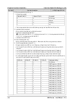
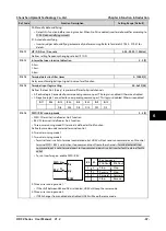
F15.24
Terminal output logic setting
000 - 0xFFF [00]
Defines that each bit (binary) represents different physical channels.
•
0: Positive logic. Connected to corresponding common port, This logic is enabled. Otherwise disabled.
•
1: Negative logic. Connected to corresponding common port, This logic is disabled. Otherwise enabled.
Thousand
Ten
Unit
Bit11 Bit10
Bit9
Bit8
Bit7
Bit6
Bit5
Bit4
Bit3
Bit2
Bit1
Bit0
-
-
-
RLY7
RLY6
RLY5
RLY4
RLY3
RLY2
RLY1 Unused DO1
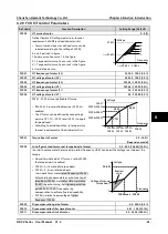
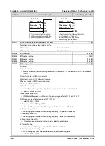
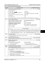
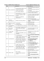
F15.27
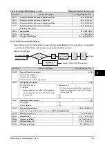
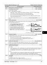
Speed within FAR range
0.00 - 100.00 [2.50Hz]
The pulse signal will output if elevator speed is
within the FAR range. As shown in the right figure.
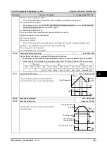
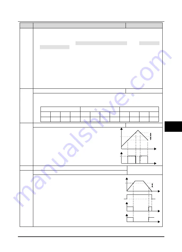
F15.28
Zero speed threshold
0.00 - Upper limit
frequency [0.00Hz]
F15.29
Zero speed tolerance
F15.28 and F15.29 defines the zero speed output
control function.
Output
Output
Time
Time
Preset frequency
DO
F15.27
F15.27
Running frequency
Zero-frequency
running output
F15.29
F15.28
Running status
Zero-frequency output
Time
Time
Time
6