


Shenzhen Hpmont Technology Co., Ltd.
Chapter 4 Electrical Installation
HD3Z Series User Manual V1.2
-15-
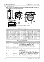
Control signal
Signal description
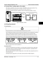
R1A / R1B / R1C
R2A / R2C - R7A / R7C
Relay output
Programmable output, contact rating: 250VAC / 3A or 30VDC / 1A
•
RB, RC: normally closed; RA, RC: normally open
Note:
Limit the current within 3A if relay terminal is to connect to AC 220V voltage signal.
4.4.2
Control Terminal Wiring
To reduce the interference and attenuation of control signal, length of control cable should limit within
50m. There should be more than 0.3m between the control cable and the motor cable.
The control cable must be shielded cable. The analogue signal cable must be shielded twisted pair.
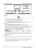
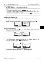
Figure 4-4 HD3Z control board conection
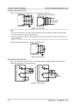
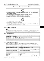
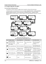
Digital input (DI) connection
Dry contact
Refer to Figure 4-5.
Figure 4-5 Dry contact connection
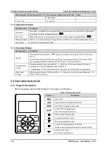
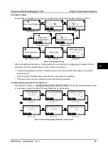
NPN contact
Refer to Figure 4-6 for NPN connection in which external
controller is common emitter output.
Figure 4-6 NPN connection
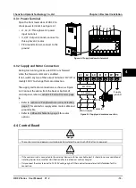
DO1
CME
GND
R1A
R1C
R1B
Relay output 1
Relay output 2 - 7
Output terminal
GND
AO1
AO2
Analogue output 1
GND
AI1
AI2
+10
Analogue
input
1
Analogue
input
2
HD3Z
GND
Analogue output 2
PE
DI1
Input terminal 1
RA
RC
Input terminal 2
DI2
Input terminal 3
DI3
Input terminal 5
DI5
Input terminal 6
DI6
Input terminal 4
DI4
GND
Current
K
DI1...DI6
HD3Z
Ex
te
rn
al
co
nt
ro
lle
r
DI1
GND
DI6
6
1
HD3Z
4