
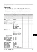


Appendix B Parameters
Shenzhen Hpmont Technology Co., Ltd.
-90-
HD3Z Series User Manual V1.2
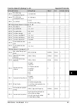
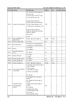
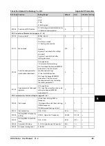
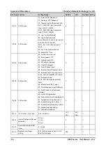
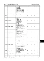
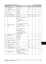
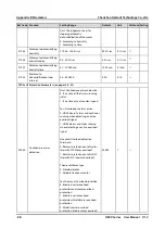
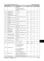
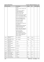
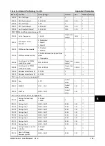
Ref. Code
Function
Setting Range
Default
Unit
Attribute Setting
F15.01
DI2 function
17: Increase (UP) frequency
18: Decrease (DN) frequency
19: Clear aux setting frequency to 0
20,21: FWD / REV jog 1 command
input (JOGF1 / JOGR1)
22,23: FWD / REV jog 2 command
input (JOGF2 / JOGR2)
24: Jog 1 command input
25: Jog 1 direction input
Note: When No.20 and 21 are selected,
No.24 and 25 are invalid.
26,27: Acc. / Dec. time terminal 1
and 2
28: Acc. / Dec. mode selection
29: Forbid Acc. / Dec.
30: Switch to normal run
32: Pause process PID
33: Forbid process PID
34: PID integral holding
35: Clear PID integral
38: Stop DC brake input
39: External stop NO contact input
40: External stop NC contact input
41,42: Coast to stop NO / NC input
43: Emergency stop
44,45: NO / NC input for external
fault
46: External reset (RST) input
53: Pulse frequency input (DI6 only)
54: Switch main / aux frequency
channel
59: Switch PID parameter
86: Activate terminal DC brake input
87: Frequency setting channel = 4
88: Disable timing start / stop
89: Disable timing frequency switch
90: Manually dehumidifying
91: Auto dehumidifying
3
1
×
F15.02
DI3 function
0
1
×
F15.03
DI4 function
0
1
×
F15.04
DI5 function
0
1
×
F15.05
DI6 function
0
1
×
F15.12
UP / DN Acc. / Dec. rate
0.00 - 99.99Hz/s
1.00
Hz/s
0.01
Hz/s
×
F15.13
Interval between terminal
detection
0: 2ms
1: 4ms
2: 8ms
0
1
○
F15.14
Terminal detection filter
times
0 - 10000
2
1
○
F15.15
Terminal input logic
setting
Bit0 - Bit5 correspond to DI1 - DI6
Bitx: DIy iput logic
000
1
○